Reply with Quote
gentleman...why my EMC was error..when i configure by my self..


I will, but for next board I will need to find again that "magic" value? :-)Originally Posted by michael_m

Maybe... don't know. I am using that track to find 2 middle points so I can drill them and rotate the board for milling the bottom layer. I weren't able to do it yet, just drill and looks like it will work.
I don't know very well the best way to mill 2 layers board...
I am doing DIY boards for a couple of developers... on a DIY project because it's not commercial viable. I would like to save all as I can.
Ok, I understand. Maybe you could comment better your code and variables?
Maybe you could write a README.txt file with explanation of your code instead inside code, looks like to me that at some time it difficult to read the code (??).
If you comment the code/I can understand it better, I will try again to change it for my needs. Can you suggest any readings? like bilinear and linear wikipedia pages or something else? How would you do this code?
gentleman...why my EMC was error..when i configure by my self..
Please ask on EMC2 community.
Looks to me that this is wrong. After reading a bit of the wikipedia page about bilinear interpolation, the grid don't need to be square nor the boundary be outside of the work.
I believe the smallest grid possible should be the 4 corners of a rectangular board. And using a boundary outside is even worst, since you are not going to mill outside. When you are milling on a corner, if you have the corner Z value probed even better if you use that value directly! and maybe the bilinear will give you right that corner value. What do you think?
I want to go ahead with your code and try to change it and discover If I have reason.
OK... the equations I used for the interpolation I got from http://en.wikipedia.org/wiki/Bilinear_interpolation. I used the simplest set of equations, which assumes the known points are in a square:There is a more general set of equations you could use to solve the situation where the known points are not in a square but I wanted something that was easy to program... If you look at my code you can see I use exactly those simplified equations above. And by the way, using those equations there is no solution for a point that lies outside the four known points.If we choose a coordinate system in which the four points where f is known are (0, 0), (0, 1), (1, 0), and (1, 1), then the interpolation formula simplifies to
f(x,y) approx = f(0,0)(1-x)(1-y) + f(1,0)x(1-y) + f(0,1)(1-x)y + f(1,1)xy ...
Alternatively, the interpolant can be written as
b1 + b2x + b3y + b4xy
where
b1 = f(0,0),
b2 = f(1,0)-f(0,0),
b3 = f(0,1)-f(0,0),
b4 = f(0,0)-f(1,0)-f(0,1)+f(1,1),
What you could do, if you didn't want to change to a different set of equations (eg like extrapolating equations or a linear interpolation equation) is put in dummy data for points you didn't probe. If you have a grid of points you probed that looked like this,
a b c
d e f
g h i
you could reconfigure the data to store it like this:
a a b c c
a a b c c
d d e f f
g g h i i
g g h i i
Note the dummy (unbolded) data on the periphery of the grid, that is a total guess (but probably an OK guess).
So if you are going to reconfigure the code along these lines, you would have to only change the probing and data storage subroutines. You could leave the rest of it alone... I have to say I'm not enthused about doing that reconfiguring myself, because it's not the way I make my boards, and I wouldn't ever use it... ;-)
But anyway, if you wanted to do it that way, what you could do is this:
(1) change the probe routine to set the probe off to probe a grid that sits just inside the max and min values (by whatever margin you choose) Shouldn't be too hard. Currently it sits just outside.After that it should just run as it does already, only on the edge it might not etch quite so accurately!
(2) reconfigure the probe data storage routine so as to leave space to put the dummy data in later
(3) when finished probing the grid, put the dummy data in the correct spot in memory.
Last edited by michael_m; 08-03-2010 at 07:31 AM.
Ok, then I would like to think as PCB area being a rectangle instead and so I will see if is possible or if equations do not get to much complex.
Hey, but what I need, is to probe just inside PCB rectangle area and interpolate values inside that area. The only question here is that you used squared pieces of area to probe and I need instead rectangular pieces of area to probe.
What do you think, will be possible? simple or difficult to adapt your code/variables?
I reckon if you made the grid squares slightly rectangular it wouldn't matter much - just so long as they were close to being square
In Wikipedia is written:
In mathematics, bilinear interpolation is an extension of linear interpolation for interpolating functions of two variables on a regular grid. The key idea is to perform linear interpolation first in one direction, and then again in the other direction.
So, if it's 2 times linear interpolation of X and after Y, I guess the "step size" can be different for each axis, letting the "regular grid" be rectangle. When they say "regular grid", does it means it needs to be square?
(...)
The result of bilinear interpolation is independent of the order of interpolation. If we had first performed the linear interpolation in the y-direction and then in the x-direction, the resulting approximation would be the same.
When you look at how the final interpolation equation pans out, it gives a weighting to the heights of the various corners of the square, depending on how far the point is from them, and uses those weightings on the height at each corner to come up with an estimated height at the variable point.
If you had a long thin rectangle those weightings would be wrong - so you would have to correct the weightings by introducing a scaling variable.
But then again we are only looking for say plus or minus 10% accuracy here. On a microscopic scale what with backlash etc etc that tool point slops around a fair bit. If your grid rectangle is within say 5% of being a square I reckon you would get a fair enough result, without having to go through and introduce a scale factor into all the equations.
I'm thinking you might be right about the regular grid thing - maybe using a rectangle doesn't matter??? Try it and see - it's an easy adjustment to make and means you don't have to fiddle about putting in dummy data...
On my head seems no problem to use a rectangle...
Even worst, I believe that probing outside of the area to mill and use the outside values to interpolation is a bad thing -- it may add errors.
I am reading and trying to understand your code right now! I don't know how to change/hack your code to have a different step to X and Y. Can you please give me some light?
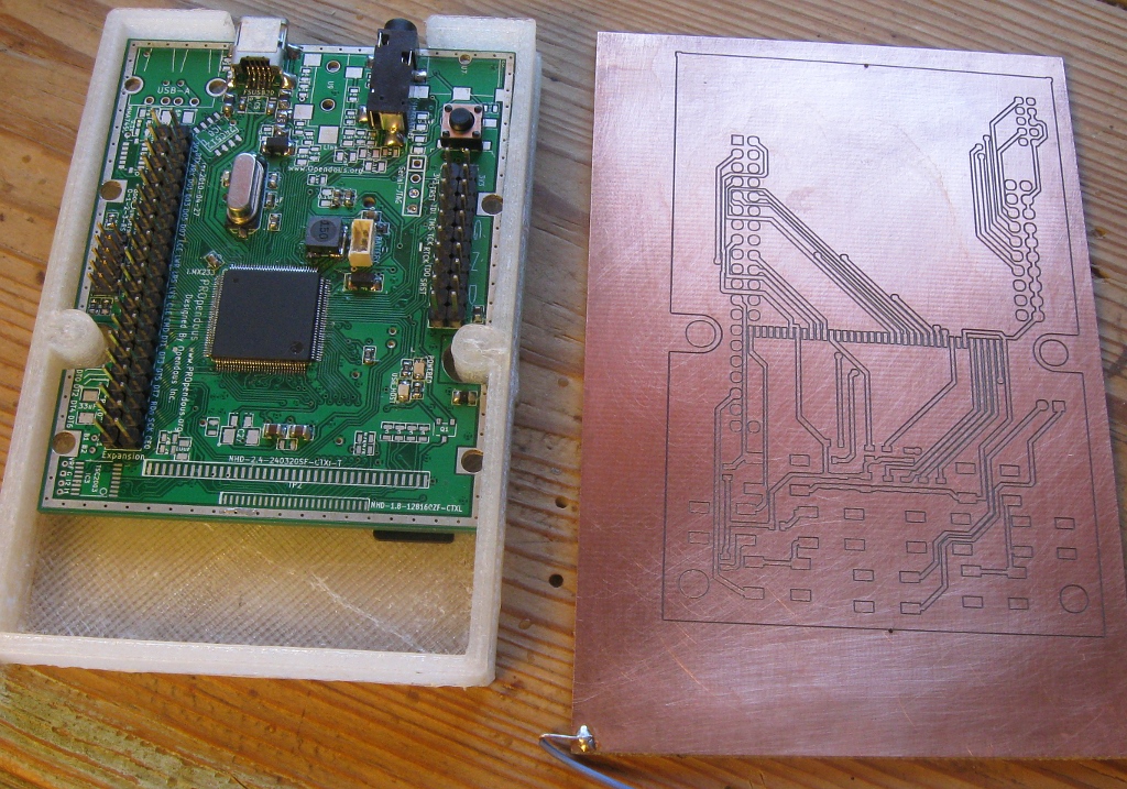
Michael sent me by e-mail a version that do rectangles grid probe. It seems to work however I just milled one face of my PCB. I need now to mill the 2nd face and after drill it.
Here one picture of the milled board (with 2 holes already for rotate the PCB to mill on 2nd face):
The board you see is from Lyre project, which is Open Source. I assembly by hand that board and even designed that plastic enclosure and printed it.
can't wait to see how your solder mask and stenciling turn out. Very nice work.
There is no requirement for the probe grid to be squares, rectangles are perfectly OK.
Poul-Henning
Great to see it works for someone else too.
I have put together a nice little Python Tkinter GUI for Etch_Z_adjust which seems to work well, and is much easier to use. I haven't put in any data validation in for the data entry boxes yet - I'm still learning how to do it. I must say I'm not finding the process for doing data validation in Tkinter Entry widgets an easy trick to learn...
If I can't work out how to do it I'll put up in a few days without any validation.
Yeah :-) -- and I used grid_clearance = 0.
So, as Paul said, grid can be rectangular. Also I am sure is better to just probe inside the full area of the board.
Right now I am having problems with my bits because they are broking... you know, they were really cheap coming from China...
I will post more pictures when I will be able to mill the board I need to.
I buy my bits off these guys: http://drillcity.stores.yahoo.net/
If they don't have exactly what you're looking for you can email them and they'll make it for you.
OK, here is a version with a Python Tkinter GUI front end. It is easier to use, I think. Change extension to .py after downloading.
This Python script will run on Windows or Linux, but at this stage the output file is still too smart for eg Mach3 and I have only tested it to verify that it works from within EMC2 running in Ubuntu 8.04 linux.
Fire the file up and a GUI will pop up. Within the one screen you choose the file to import, the units to use, a method to define the probe grid (either specify the exact number of gridlines, or give an approximate grid step size), and then give the appropriate grid parameters. You can also enter the etch depth if you wish. The grid size is only as big as the limit of etch moves on the work, no bigger.
I found a way to validate data entered into the Tkinter Entry widgets - it is not that intuitive, nor well explained in the Python documentation, but the method I found on Google does work. It rejects negative amounts and non float and/or non integer values.
Further possible improvements to this down the track:
- Check to see if you need to probe, before you probe (not all probe points on the grid are near an etch line, so there can be a lot of unnecessary probing going on)
- Add check boxes (and subroutines) to optimise etch paths and/or optimise moves between drills
Jay C I haven't incorporated the CLI version of opti_qt to this as yet as I only have a Windows .exe file... and this Etch_Z_adjust version currently only produces output that Linux based EMC2 can use.
Can you give me some tips on how to compile opti_qt_CLI on Ubuntu 8.04, so it can run from inside EMC2???
Yep, super easy to compile.
g++ opti.cpp -o opti
G++ Linux Tutorial
-Jay
Jay I compiled your opti CLI under Ubuntu 8.04 as per your instructions, and it runs perfectly from inside EMC2 using this Python code:
import subprocess
p = subprocess.Popen([opti_path, file_in_path])
I'll add it to the Etch_adjust GUI when I get some time later this week.
Thanks!
 Posting Permissions