Reply with Quote
Can you post the file?


Has anybody else been having trouble with Z Level Finish?
I am not able to get the links to change to Follow, Horisonal or Vertical, Spiral it will only do a full retract. I do have Linking on boundary set to Follow but still get full retract.
Am I doing something wrong?
Similar Threads:
- Need Help!- Z Level Finish
- Need Help!- Z Level Finish!
- Need Help!- Z level finish Boundries
- Z Level finishing minimum for finish
- Z Level Finish
Can you post the file?
Hi BurrMan
Here is the file. I have tried all kinds of different setting with no luck
Thanks
Roger
Options-by area........
by level is forcing the toolpath to review each level.
Thanks Much BurrMan
That was simple.
I've been having different issues with Z-Level finishing, but as I'm newer to machining my parts off of 3d models, I'm not sure if my expectations are aligned with reality. My problem is that Z-level finishing is not seeming to pick up where Z-level roughing left off. Roughing does exactly what I'd expect, and I set it to leave a small amount for the finish pass. The finishing pass does not seem to recognize horizontal planes as something that needs to be finished, so essentially I get a raised portion of material left over from the roughing pass, and no apparent way to get rid of it. I'm in V24 Mill Standard, if that makes any difference
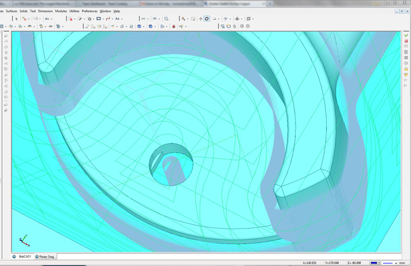
The green pass is the roughing pass and the pink pass is the finishing pass. You can see that the finishing pass completely ignores the flat surfaces (which were selected). I eliminated sprues that hold the part to the stock, just to make the file the most simple format it can be in. Normally, I have some sprues there to keep the part to the stock when the material is flipped for machining the back side. Everything comes out perfect and well indexed, but the flat surfaces are incompletely machined. I've tried various additional passes just to those surfaces with no luck, though I'm admittedly still learning V24. File is here:
https://files.secureserver.net/0sK5Gjge5nF9sv
I'll be removing the link later, please do not redistribute file.
Thanks!
-Mike
Z Level Rough has a step down and a step over amount that you can define.That makes it good for verticle and horizontal surfaces.
Z Level Finish only has a step down amount.So that is great for vertical surfaces.Horizontal not so much.
I am not %100 sure,but if you do indeed have Equal distance offset tool path,use that for your flatter areas.
It looks almost like you could use 2D tool paths for some of the horizontal work too.That's just by looking at your pic though,I might not be seeing something.
Here's a link for V24 Videos.Worth checking out.
bobcad v24 videos - YouTube
If I drew a 2d profile of the surfaces needing machining, I could run a pocket tool path on them with the Z value set to the correct depth. However, that's extra work that I'd expect I should not have to do when I've gone through the trouble to model the part as a solid. So far, I have not been able to run any tool path (2d or 3d) on just the surfaces to clean them up, and I've tried the options available to me. Equidistant Offset is part of the "Pro" package which I do not have.
If I run a second Z Level roughing pass, but with the step down set to .05mm (for example) and set to leave nothing, it does recognize the surfaces that the finishing option doesn't and produces a tool path that would cut them. The problem is that it also thinks that it must remove all the material around the part as well, even though the previous roughing has already done so, and produces a tool path that would be cutting air for hours before it would actually get to the part. This makes that option unusable.
Alright, with the Z Level Rough and Z Level Finish toolpaths you are looking at a side wall roughing and finishing pass. It will not finish bottom surfaces. The reason is the Rough and Finish Z Level passes are doing a step down. What I mean by that is it is doing a slice at a defined depth that you have done so think of it as slicing the model where a plane intersects every .030" If you were to do a step down of 1 inch you'll see that there will be a toolpath down every 1"
What you'll find is that with the Z Level Rough if you have a level that steps down and it is in-between one of your steps it will not finish that to size. This applies to Rough as well. I have added an exaggerated picture of the issue that you'll run into.
The only thing with your package that I could say you would be able to do is either use the pocket feature or finish instead with a Slice Planar which will finish to the surface the other options are slice spiral or radial.
If you were to have V24 with 3 axis pro I would say you could use the Flatlands feature and Equidistant. If you were to have V25 with Pro I would say you could use Pocket with geometry selected off the solid, Flatlands, Advanced Rough with Machine Flatlands, or Equidistant.
As a note you won't necessarily need to redraw the 2d geometry you can instead use the extract edges tool under utilities to get the edges for your pocket. I would recommend doing this onto another layer for easier selection.
As far as a toolpath that is cutting air that is because it's not recognizing what has been cut. You'll find that in the Advanced Rough you are able to do a rest rough operation. What this allows you to do is basically compute what has been cut and what needs to be cut with the current tool you have selected.
If you use the help it is explained more in depth in the feature. I copied out directly from the help system for V24 what is said:
Rest Roughing - This option calculates a tool path that will remove all the non-machined areas left be previous large roughing tool. The previous tool is used to identify accurately the areas on a 3d component by sweeping the diameter across the whole part being machined. In this way any unmachined areas are identified and passed to the system and the tool path is calculated. Rest roughing tool path does not require the whole part to be machined again. It will machine only those areas that are left out by previous tool. On intricate parts multiple rest rough tool paths are required to remove as much material as possible before running semi finishing or finishing tool paths. In rest roughing tool path you will normally use a smaller step down as the cutter size reduces than the cutter used for the previous roughing tool path. Shown below is an example of using the Advanced Rough feature for Rest machining, along with an image showing the rest roughing strategy in blue.
I think its kind of like cutting flat lands which is in the pro pack as well, equal distance is very nice to have but maybe as an alternative you can try this
Use Z finish as you are doing and then add another Z rough with tight step overs but pick top of job and bottom of job for the horizontal surfaces at lease your not cutting air. You'll probably have to make a separate feature for each horizontal surface.
RAF,
You still end up cutting in air because the roughing process takes the extents of the part and adds about two passes beyond the furthest point. That is not adjustable, it does so on it's own. The other problem is that it will only work if you select the entire part, because if you select only the flat surfaces it will make a rectangle past the extents of the part, which wipes out the rest of the part within that rectangle.
Jesse,
Planar Slice doesn't work for much of the same reason as above. If you select only the surface needing machining, you end up with gouging at the perimeter because even when you have set the tool path to not go beyond the part boundary, it only keeps it within the boundary to the tool center, resulting it gouging at the vertical wall beyond the part edge. The only way Planar Slice works is if you select the entire part and run a path on the entire part. This would then result in cutting surfaces that are already done (and potentially gouging them slightly). Planar Slice could be used instead of Z-Level Finish, but the part is one that would be better machined with Z-Level Finish in my estimation. Planar Slice would produce the same finish on the shaft of the part, but an inferior finish on the round walls of the part.
For the moment, since I don't have the "Pro" package, it appears that the only option that works (within a reasonable degree of effectiveness) is to generate 2d geometry and pocket off of it. I have never used the extract edges function, so I'll have to try that out and see how it goes. I wouldn't mind pocketing so much if it were easy to generate the correct 2d geometry, so maybe that will work out.
"For the moment, since I don't have the "Pro" package, it appears that the only option that works (within a reasonable degree of effectiveness) is to generate 2d geometry and pocket off of it."
As good as I can tell from your pic.,2D pocket would not only be the best,but the fastest and preferred method.Unless there is something I just can't see in pic.Since you said you were taking pic. down soon,I am betting you cannot share file ?
From what I gather of the CAD/CAM package you have and the choice of tool paths at your disposal,I am thinking to do the flat area,you would create new layer,extract edges,then you would want to make the pocket larger on the "open" side.The reason you would do that is to make room for the diameter of the tool to fit in the pocket.Then I would 2D pocket the flat area.If you can share file,we'll show you.
As Jesse points out, the z rough wont be a good finish op, unless you can get the falt bottom surface at one of the exact steps from the start, because it is looking at "the material being removed" and not "the surface being cut"... But, if you can get this, or also in the slice planar options, you can select the entire model (Correct. You need to do this and not just a single surface, because the toolpath wont know what to avoid) And then set a top and bottom of job and limit it to a single pass depth, to use as a finish.Originally Posted by mmoe

The z level finish will "only do vertical cuts". Anything that starts to plane out, and the path will spread to an undesirable finish.
If you are limited to "only the standard toolpaths", then slice planar is your finishing friend. (Or one of the other slice paths, depending on the shape of the model)
Slice spiral is a good replacement for "rounded/oblongy type shapes as a replacement for z finish if you can get a good oblong/oval shape of your part with minimal "air" to complete the spiral. Again, top and bottom of job to limit the area of the cut.
There is a link to the file in the same post as the photo. It's just a bit below the image. I'll be leaving the link for a couple days, then removing it but I'll leave the image.
I'm able to do the 2d pocket, however I have not learned the extract edges feature yet, so it's kind of a pain in the rear to draw the pocket out when I already modeled the part. From the sounds of it, the extract edges feature will solve that problem and make it a little more convenient. I'll take a look at that feature later and see how it works.
Just as an FYI, I will be adding sprues later to hold the part in the material, but I've not found that it makes much difference as the tool path goes. Z-Level roughing and finishing work around the sprues correctly and have not given me a problem so far. I'm still experimenting with how thin I can make the sprues before they start wiggling under machining.
Ok, this may be a long winded explanation but it will explain many things:
First:
If you do not know how to use the extract edges function go to its location using utilities> extract edges> single edge or whole side. Do not Click on either function hover your cursor over it. Then press the F1 key on your keyboard. This will bring up the help which explains exactly how to use the function you were hovering over.
*Note - If you have an HP computer it may be linked instead to the computers help rather than permitting a program to access it's help. To get around this either disable it on that computer or use the Shift+F1 to add a "?" to your mouse then go the directory in the toolbar.
Second:
The reason why you are getting gouges is because you're not selecting the whole model. When you actually compute a toolpath it tessellates the model turning it into a mesh with a tolerance that it can vary from the solid and then the toolpath is laid on this tessellation with a tolerance that it can vary from. So if the model is not completely selected there will be gouges because it does not do a calculation for something that is not there. So what you will need to do is select the whole model and use a boundary.
You are correct in-that the boundary controls only tool tip this is how it functions. To correct this you will want to use the offset function to offset the boundary inward by the radius of the tool. This will allow for proper toolpath creation. All of the 3d toolpaths operate in this fashion.
*Note - The offset function is under Other.
Third:
As Jrmach had mentioned to get the 2d Geometry you will need to extract the edges onto another layer. To further break this down follow the quick steps I have listed below:
Create a layer
Select layer (make it active)
Use extract edges tool to extract the edges that you are wanting to work with.
Hide CAD layer that solid is on or use the View> Blank tool.
Add toolpath
This should function correctly for you.
Thanks Jesse and Jrmach,
Over the last couple days, I got pretty proficient with the extract edges proceedure, which I then applied a pocketing routine to. Works well, however I ended up calling Bobcad and upgrading to V24 "Pro" for a price that was agreeable. The Flatlands function is pretty much exactly what I was hoping for, so I think I'll feel I got my money's worth in the long run. I guess that I would recommend that anyone who expects to routinely machine 3d models go ahead and spend the little extra on the "Pro" version, it's definitely more capable. If you spend most of your time machining in 2d, extract edges and pocket will work when you need it, but I'm hoping that I'll be doing enough 3d work to justify the additional expense of Pro. Bobcad's service regarding the upgrade was very good and the sales rep was easy to work with.
-Mike
Yeah,Pro opens up a lot more options.You should of gained Equal Distance Offset too,I think.Explore that one for 3D,,it'll come in handy for nice finishing paths.
I was messing around with Equal Distant Offset last night, and can see how it could be useful at times. It's an odd toolpath though, in that it doesn't really conform itself to shapes a very logical manner. For instance it looked like it would be perfect for a Z-Level type finish of a 5 spoke wheel (like an aluminum car wheel), but instead of machining in a round manner (the face is dished out and the object is circular with holes to define the spokes), it follows the shape of the spokes all the way into the center of the wheel. This produces a somewhat star shaped tool path on otherwise round surfaces. Not saying it won't be useful, just that I haven't yet got a good idea of how it will work to predict the outcome before generating the tool path.
Overall, the pro version definitely makes some of those more difficult tasks a bit easier. Between Advanced Roughing and Flatlands, I'm not sure how I got along without it now. I think Advance Rough will reduce the roughing time by perhaps as much as 50%. The standard Roughing seems to always cut a lot of air for no real reason.