Noob Q: How do I make this on a X3 mill (27in dia)


Results 1 to 13 of 13

Thread: Noob Q: How do I make this on a X3 mill (27in dia)

  1. #1
    Member
    Join Date
    Jul 2006
    Location
    US
    Posts
    741
    Downloads
    0
    Uploads
    0

    Default Noob Q: How do I make this on a X3 mill (27in dia)

    Howdy,

    This may be a stupid question, but since I'm a noob : I would appreciate any tips . I would like to make the attached pic piece in a Sieg X3 CNC mill (which I'm still in the process of quoting). The right tool to do this would probably be a waterjet... still... If we were to take this as dare how would we go about doing it?

    It is basically a 27" disk of 1/8" thick carbon steel with a bunch of symmetric holes that are way over the capacity of the mill table.

    The radial lines are just symmetry lines -- I did a triangle with the basic holes and then a polar array 16x. Most of the holes are for screws so they would be countersink. The reminder holes are for shafts, but they will rotate rather gently and all that will be needed is a Teflon thingy (sorry about the technical jargon) to keep it from squeaking. The precision would be fine at 0.01". The whole piece is part of a braiding machine.

    The first thought was to break things up into smaller pieces, but I think we won't be able to put humpty dumpty together again -- or he will not be able to walk . The next idea was to use the fact that most of the holes are a few inches from the edge. So, perhaps, one could figure out a clamping and indexing that simply allowed you to do the next section by indexing on the holes you just made for the current section... we would also cut/finish the circle edge at the same time -- or in a second pass.

    Does this stand a chance of working? Have you done anything similar? Did it come out all right? Hints, Tips?

    Thanks

    Similar Threads:
    Attached Thumbnails Attached Thumbnails Noob Q: How do I make this on a X3 mill (27in dia)-gif  


  2. #2
    Member
    Join Date
    Jul 2006
    Location
    US
    Posts
    741
    Downloads
    0
    Uploads
    0

    Default

    As I finished typing this I thought that instead of indexing only on the previous holes perhaps we could index on the center of the disk (even if the center hole can not be done in the mill). That way the radial distances would be safe from drift and the errors would only accumulate "in the angles" as we "release", "rotate 360/16" and "clamp".

    Hmmm...

    Does not fit in the planned enclosure I guess I'll need to take the front of it off or something.


  3. #3
    Registered
    Join Date
    Apr 2005
    Location
    us
    Posts
    403
    Downloads
    0
    Uploads
    0

    Default

    Ed from New york,

    I'll give you a quick thought, you could bolt a piece of plate (or a fixture) maybe 14X16 inches on your table and then mount the rotary table on the plate (or fixture) Then center your work piece on your rotary table.

    Understand that this comes from a man that has never used a rotary table. But gives you a concept to start with.

    Hope it helps,

    Ron (from Mississippi)


  4. #4
    Member
    Join Date
    Jun 2005
    Location
    USA
    Posts
    1015
    Downloads
    0
    Uploads
    0

    Default

    i'd do what ron is suggesting.


  5. #5
    Registered
    Join Date
    Feb 2006
    Location
    us
    Posts
    1187
    Downloads
    0
    Uploads
    0

    Default

    I agree with Ron, Thats the way i would do it. If your starting off with a square piece of metal and you want to mill it round you could chop saw the corners and make it into an octagon and then like Ron said bolt a bigger plate underneath to support and then use a rotary table or indexer to do the holes. The hole in the center looks like you would have to hand drill it if you don,t have a radial drill.


  6. #6
    Gold Member
    Join Date
    Jun 2003
    Location
    United States
    Posts
    1365
    Downloads
    0
    Uploads
    0

    Default

    Here is how I would do it, I'd take a peice of steel or something, drill and tap a hole in it for a bolt, then drill a hole off to the left for a pin for indexing, then clamp the part down, drill the first pie section of holes, take it off, insert the pin and rotate the part and set it back on, drill the next pie, and so on.


    Jon

    Attached Thumbnails Attached Thumbnails Noob Q: How do I make this on a X3 mill (27in dia)-rotaryjig-jpg  


  7. #7
    Member
    Join Date
    Jul 2005
    Location
    Canada
    Posts
    12177
    Downloads
    0
    Uploads
    0

    Default

    Quote Originally Posted by JFettig
    Here is how I would do it, I'd take a peice of steel or something, drill and tap a hole in it for a bolt, then drill a hole off to the left for a pin for indexing, then clamp the part down, drill the first pie section of holes, take it off, insert the pin and rotate the part and set it back on, drill the next pie, and so on.Jon
    I would suggest going halfway round one way then back to the start and halfway round the other to reduce accumulative error.


  8. #8
    Gold Member BobWarfield's Avatar
    Join Date
    May 2005
    Location
    USA
    Posts
    2502
    Downloads
    0
    Uploads
    0

    Default

    While you're at it, bolt a stepper to your rotary table, hand write the g-codes to run it (you could even swap your X-axis over to drive the table temporarily, or consider this a 4th axis), and you can automate the process pretty nicely. The trick is going to be aligning the position of the rotab versus your spindle to get the edge to hole diameter correct. Mount the mill and the rotab down to the same plate, perhaps allowing multiple mounting holes for the rotab to address the differing radial hole distances from edge or center. Looks like you need 5 positions for the rotab if you count the 4 hole distances plus a position to mill the circular edge.

    OTOH, if you are dead set on making these discs (what are they?), you ought to look at a bigger mill or even building yourself a router table. You could also make a little jig to spin the plate while a plasma cutter takes an initial rough cut.

    Lastly, this would be easily outsourced to a shop with large enough tools. It would also be easy to build an inexpensive dedicated jig using your mill that would let you make these without a rotab too.

    Best,

    BW


  9. #9
    Registered
    Join Date
    Jun 2005
    Location
    USA
    Posts
    866
    Downloads
    0
    Uploads
    0

    Default

    What would the diameter of the holes be?


  10. #10
    Member
    Join Date
    Jul 2006
    Location
    US
    Posts
    741
    Downloads
    0
    Uploads
    0

    Default

    Wow great. Thanks for all the responses.

    Bob, this is the table of a braiding machine with 16 carriers. The larger holes hold the rotating "carrier passers" (I'm sure they have a proper name) which spin at a modest speed and that with the help of levers send 8 carriers clockwise and 8 carriers counterclockwise. The smaller holes are to hold the carrier guides which are static in relation to the table (3 small bolts each) and keep the carriers in the desired path as they are moved by the "passers". This drawing is missing additional holes that are used to hold the shafts that transmit angular movement to the levers that push the carriers from one "passer" to another because I have not done the math yet. The drawing is also missing the holes for a core "wire" which in my case will be a cotton rope. The way the table works is that the carriers with the wires weave in and out in relation to each other forming a tubular braid on top of the cotton center

    I'll probably cut the initial "circle" with a handheld plasma torch as you suggested... this thing is starting to get seriously out of control -- I live in an apartment

    Phantomcow2: the larger hole is 1/4" and the smaller hole is 1/8" -- I can change the dimensions as long as I change the parts that fit there.

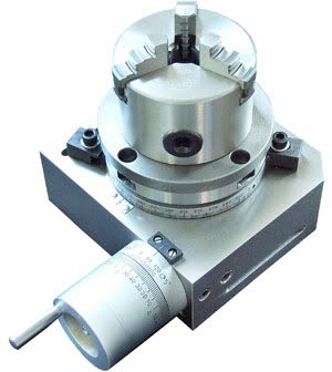
    Ron, Runner, Zip: the rotating table I was planning to get is this one. Not sure if this little table would be able to hold that large piece steady because the milling is taking place all the way at 10" to 14" from the center.


    With JFettig's and Geof's suggestion the critical pieces are 1) that the arm supporting the disk be rigid enough and with a way to be clamped nicely to the table and 2) that the holes and the indexing pin be tight enough so that there is no play because the errors will accumulate -- which means I have to do the pin in a lathe or something.

    I think I'm going to go with that


  11. #11
    Gold Member acondit's Avatar
    Join Date
    Apr 2005
    Location
    USA
    Posts
    1778
    Downloads
    0
    Uploads
    0

    Default

    Just a suggestion. I would make a piece out of plywood first, just to check my set up and calculations.

    Alan


  12. #12
    Gold Member
    Join Date
    Dec 2004
    Location
    Newtown, CT, USA
    Posts
    524
    Downloads
    0
    Uploads
    0

    Default

    I'm assuming that you are just making one of these. If you need to do this in production, find someone with a suitable machine.

    I would use a variant of JFettig's suggestion. First, I would layout one instance of the pattern on an aluminum template and drill it with pilot holes. Then I would layout the circle on my material. I would manually layout the four quadrants (since you have sixteen repeats). -- Use a compass and layout dye.

    Then, I would layout the rest of the holes, recognizing that I can do eight of them by indexing off the four quadrant lines. The remaining four would be done as JFettig suggested, but I would just use the template and a center punch.

    I would then drill all of the holes using a drill press (or use your mill as a drill press). Drill the holes undersized and ream them to fit the bushings you've selected.

    There should be no problem getting the holes within .010 using this approach if you are careful.

    Ken

    Kenneth Lerman
    55 Main Street
    Newtown, CT 06470


  13. #13
    Member
    Join Date
    Jul 2006
    Location
    US
    Posts
    741
    Downloads
    0
    Uploads
    0

    Default

    Yeap, I only have to make one... or I should say... one "good one"

    I like the idea of trying it off in plywood first

    Thanks!

    Last edited by Ed from NY; 08-03-2006 at 12:23 AM.


Tags for this Thread

Posting Permissions

  • You may not post new threads
  • You may not post replies
  • You may not post attachments
  • You may not edit your posts
  •  


About CNCzone.com

    We are the largest and most active discussion forum for manufacturing industry. The site is 100% free to join and use, so join today!

Follow us on


Our Brands

Noob Q: How do I make this on a X3 mill (27in dia)

Noob Q: How do I make this on a X3 mill (27in dia)