New Machine Build Granite surface plate lathe


Page 1 of 7 1234 ... LastLast
Results 1 to 20 of 123

Thread: Granite surface plate lathe

  1. #1
    Registered
    Join Date
    Apr 2007
    Location
    New York, NY
    Posts
    521
    Downloads
    0
    Uploads
    0

    Default Granite surface plate lathe

    I've been thinking about this and collecting parts for at least a couple of years. Thanks to everyone on CNCzone and elsewhere that has posted pictures and info of their CNC machine builds. Especially: 5bears, Bob Warfield, Guldberg, JH-Q, S_J_H, The Blight. (edit: how could i forget mackeym !)

    I started with a 18x24x3 Granite surface plate. I drilled half way through from the top and then half from the bottom. All the components will be bolted down rather than using epoxied inserts.


    Similar Threads:
    Last edited by will gilmore; 10-28-2009 at 09:06 AM.


  2. #2
    Registered
    Join Date
    Nov 2003
    Location
    rockford, il
    Posts
    104
    Downloads
    0
    Uploads
    0

    Default

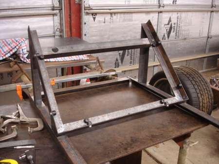
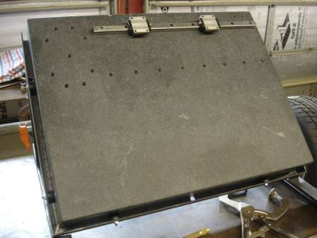
    I will be watching this with great interest. I have drilled and epoxied tapped inserts into a 18 24 4 surface plate and bolted up the ballscrew and rails. I am currently laid off, and cannot go further until I find steady work. Did you drill dry, or did you use a water swivel?
    I used a (leaky) water swivel, that i had to put a bag over with zip ties, but it was still a messy job. I could not believe how easy it is to drill granite. What will you be using as a headstock? Will this be a gang lathe?


  3. #3
    Member jalessi's Avatar
    Join Date
    Feb 2007
    Location
    United States
    Posts
    4553
    Downloads
    1
    Uploads
    0

    Default

    Will,

    What type of drill bits did you use?

    Jeff...

    Patience and perseverance have a magical effect before which difficulties disappear and obstacles vanish.


  4. #4
    Registered
    Join Date
    Apr 2007
    Location
    New York, NY
    Posts
    521
    Downloads
    0
    Uploads
    0

    Default

    tootalew - we talked about sharing a granite plate at one point. lets see some pictures of your project.

    i did use a water swivel. you can see it in the 3rd and 4th pictures. i drilled one hole trying to stop the spray with rags and wood blocks. after that i made the spray shields shown the in the picture. there are two types of spray that i found. when you first bring the drill down to the surface of the granite with the water flowing the water sprays out horizontally. the two "C" shaped pieces fit around the water swivel to stop this. the second spray happens when you have the hole started. the water sprays out of the hole vertically and hits the bottom of the water swivel and gets every where. i put the cylindrical piece of sheet metal around the water swivel to contain this spray. after i had these pieces in place i could drill with next to no water spray.

    jeff - i used a 3/8 sintered diamond drill from ukam http://ukam.com/webcatalog_drills_ordering.htm


  5. #5
    Registered
    Join Date
    Nov 2003
    Location
    rockford, il
    Posts
    104
    Downloads
    0
    Uploads
    0

    Default

    Will, I will get some pictures posted soon. I did not see all the photos before my response. I used a short section of pvc pipe for my "moat" but that vertical spray is hard to control. I used a 5/8" core bit, going down about an 1 1/2" then took a thin screw driver wedging it in and a quick slap from hand the granite slugs broke out very easy.


  6. #6
    Registered
    Join Date
    May 2006
    Location
    Denmark
    Posts
    573
    Downloads
    0
    Uploads
    0

    Default

    Interesting project (hurray, I was mentioned :-). Looking forward to more pictures of the beast. Any drawings/conceptual art to show us the goal?


  7. #7
    Registered
    Join Date
    Apr 2007
    Location
    New York, NY
    Posts
    521
    Downloads
    0
    Uploads
    0

    Default

    Not a lot of progress. Other stuff going on and waiting for materials and hardware.


    the second image should give you an idea what is going to happen. headstock will go on the left.


  8. #8
    Member
    Join Date
    Feb 2009
    Location
    usa
    Posts
    6028
    Downloads
    0
    Uploads
    0

    Default granite lathe

    Very cool. We just pulled a "granite lathe" out of service and threw it away. Had full laser feedback for position/tilt/ya/and temperature. It was built back in the late 70's. About 100 ton of granite total. Accuracy .000005, flatness.000001. Yes, nano-inch resolution. Pretty impressive in its day. Room temp control was .5 deg, machine temp control was .001 deg. It actually made the lens for the Hubble telescope. I love watching the machine builds here.


  9. #9
    Registered
    Join Date
    Apr 2007
    Location
    New York, NY
    Posts
    521
    Downloads
    0
    Uploads
    0

    Default

    Finally some progress. Got some tube for the stand and have that tacked together. Started machining the spacer that holds the headstock off the granite and will hold the Z stepper and ball screw.


  10. #10
    Registered
    Join Date
    Apr 2007
    Location
    New York, NY
    Posts
    521
    Downloads
    0
    Uploads
    0

    Default

    More progress. Have the Z screw mounted. Pretty soon I'm going to need to start thinking about electronics.


  11. #11
    Registered
    Join Date
    Jan 2007
    Location
    US
    Posts
    97
    Downloads
    0
    Uploads
    0

    Default

    nice project.
    please continue the updates.iam very much interested to a lathe built on granite


  12. #12
    Member
    Join Date
    Feb 2006
    Location
    holland
    Posts
    12
    Downloads
    0
    Uploads
    0

    Default

    That is looking great!
    The granite makes it look like it's going to be a very accurate machine

    What sort of travels are you aiming for? And are you going to mount a tailstock?


  13. #13
    Registered
    Join Date
    Apr 2007
    Location
    New York, NY
    Posts
    521
    Downloads
    0
    Uploads
    0

    Default

    Thanks for the comments. I'll continue to update this thread as I make more progress.

    I'll end up with around 12" Z and 12" X (for gang tooling). I have two extra bearings that will fit on the Z axis rails that I could build a tail stock on. that would reduce the Z travel and eliminate the gang tooling. We will see.


  14. #14
    Registered
    Join Date
    Apr 2007
    Location
    New York, NY
    Posts
    521
    Downloads
    0
    Uploads
    0

    Default

    Progress. Drilled and tapped the plate that holds all the linear bearings.


  15. #15
    Registered
    Join Date
    Apr 2007
    Location
    New York, NY
    Posts
    521
    Downloads
    0
    Uploads
    0

    Default

    I told my self I wouldn't buy any electronics for this project until I was fairly certain I could complete the mechanical aspects (this is my first real machining project). I'm now pretty sure I can do that plus I need info on the electrical parts (home switches, stepper motors, etc) to complete the machining.

    Here is my first electrical question:

    I designed this lathe for NEMA23 steppers direct driving the ballscrews. My ballscrews are Z: 4mm(.1575")/rev, X:2.5mm(.0984")/rev. Precision is ok at .00008"/microstep on Z and .00005"/microstep on X. Which steppers to use? I had originally thought about the 570 oz in steppers from Keling but the idea of using a Gecko G540 intrigues me. Would the 371 oz in steppers from Keling be enough? http://www.kelinginc.net/NEMA23Motor.html

    That's all for now. If I choose the G540 I have a couple wiring questions.


  16. #16
    Registered
    Join Date
    Jul 2007
    Location
    Sweden
    Posts
    887
    Downloads
    0
    Uploads
    0

    Default

    It all depends on what kind of linear force you need and at what speed. As you probably know, the torque of a step-motors falls off with increased speed, the higher the inductance of the motor is the faster the torque drops. So, it's not necessarily true that a step-motor with a higher holding torque will perform better than one with lower holding torque when you factor in the speed at which you want it to run and the voltage limitation of the drive you are using.

    The cure against falling torque is increased voltage, the higher inductance motors require higher voltage to reach the same speed as a motor with lower inductance. On the other hand, to get the same holding torque the low inductance motor will have a higher current rating.

    Keling should be able to provide you with a speed/torqe curve that shows how much torque the motor delivers at a certain speed and with a certain supply voltage.

    Let's say you want 4000mm/min on your 4mm screw. That's 1000rpm and let's say that at that speed the torque has dropped to 100 oz-in (1Nm). With the 4mm pitch screw you'll then get 1 / (4/PI/2/1000) = 1570N of linear force, not counting any inefficiency of the ballscrew etc.

    If you spin the Z-xis screw at 1000rpm you'll obviously get 2500mm/min, the linear force would be 1 / (2.5/PI/2/1000) = ~2500N, again not counting the inefficiency of the screw any any other losses.

    To be really accurate you should also factor in the force it takes to accelerate the slides etc but that can be quite hard to do. If you calculate with a hefty safetyfactor (something like 100%) you should be on the safe side.

    I have no idea how much force you need though but I think 1500N sounds like quite a healthy number - and you probably won't do much cutting at 4000mm/min.

    HTH.
    /Henrik.


  17. #17
    Registered
    Join Date
    Apr 2007
    Location
    New York, NY
    Posts
    521
    Downloads
    0
    Uploads
    0

    Default

    HO- thanks for breaking down the math. The torque-speed curve isn't on the keling website. Keling does have the torque-speed curve for the 387 oz in motor with higher inductance (4.1mH vs 2.8mH). http://www.kelinginc.net/KL23H284-35-4BT.pdf At 20,000 pps, 1/8 step (20,000 *60 / 8 = 750 rpm) torque is slightly under 1Nm. Looks like you are in the right ballpark with your numbers.

    The bottom line is I've never built or run a CNC machine before and I have no idea what speeds and torque I need.


  18. #18
    Registered
    Join Date
    Jul 2007
    Location
    Sweden
    Posts
    887
    Downloads
    0
    Uploads
    0

    Default

    Well, as I said - I can't say you need this or that amount force to achive this or that kind of cut in a certain material but again, 1500N is quite a bit. I see now that I, in my previous message, said 1Nm is 100oz-in which obviously isn't correct. The math was based on the 1Nm number though so it shouldn't make any difference. Don't hold me responsible for it being correct though, I do make mistakes....


  19. #19
    Registered
    Join Date
    Apr 2007
    Location
    New York, NY
    Posts
    521
    Downloads
    0
    Uploads
    0

    Default

    I looked it up 1 Nm = 144.61 oz in.

    1500N seems like a lot. I also haven't worked out what will be driving the spindle but I'm sure I won't be doing heavy cuts with this lathe.


  20. #20
    Member ger21's Avatar
    Join Date
    Mar 2003
    Location
    Shelby Township
    Posts
    35538
    Downloads
    1
    Uploads
    0

    Default

    I looked it up 1 Nm = 144.61 oz in.
    That's correct for torque, but not force.

    1N of force = .225 lbs.
    1500N = ~337 pounds of force.

    Gerry

    UCCNC 2017 Screenset
    [URL]http://www.thecncwoodworker.com/2017.html[/URL]

    Mach3 2010 Screenset
    [URL]http://www.thecncwoodworker.com/2010.html[/URL]

    JointCAM - CNC Dovetails & Box Joints
    [URL]http://www.g-forcecnc.com/jointcam.html[/URL]

    (Note: The opinions expressed in this post are my own and are not necessarily those of CNCzone and its management)


Page 1 of 7 1234 ... LastLast

Tags for this Thread

Posting Permissions

  • You may not post new threads
  • You may not post replies
  • You may not post attachments
  • You may not edit your posts
  •  


About CNCzone.com

    We are the largest and most active discussion forum for manufacturing industry. The site is 100% free to join and use, so join today!

Follow us on


Our Brands

Granite surface plate lathe

Granite surface plate lathe