Tree Journeyman 320 B Retrofit - Page 4


Page 4 of 9 FirstFirst 1234567 ... LastLast
Results 61 to 80 of 179

Thread: Tree Journeyman 320 B Retrofit

  1. #61
    Registered
    Join Date
    Apr 2007
    Location
    New York, NY
    Posts
    521
    Downloads
    0
    Uploads
    0

    Default

    I also just realized my link in post 54 just goes to the general gecko support page. I wanted to link to this image:

    http://www.geckodrive.com/images/fck...EStop800PW.jpg

    You can find the explanation in application notes>>servo drives>>electro mechanical estop


  2. #62
    Community Moderator Al_The_Man's Avatar
    Join Date
    Dec 2003
    Location
    Canada
    Posts
    24221
    Downloads
    0
    Uploads
    0

    Default

    The AMC have an internal jumper that will configure the Enable active hi or low.
    In the default condition you can use a N.C. contact.
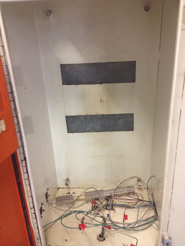
    The AC neutral and all DC commons normally have their own common terminal strip but these should have a conductor connected to the star point ground block.
    An important thing is to ground or bond motor frames and moving parts of the machine to this block.
    The siemens PDF is a good ref for the bonding practice.
    http://www.automation.siemens.com/do.../emv_r.pdf?p=1
    Ground Practices
    If you read section 6 of the sieimens PDF, they advise a common current recommendation of grounding both ends of a shielded cable when proper bonding practice is observed.
    Al.

    CNC, Mechatronics Integration and Custom Machine Design

    “Logic will get you from A to B. Imagination will take you everywhere.”
    Albert E.


  3. #63
    Community Moderator Al_The_Man's Avatar
    Join Date
    Dec 2003
    Location
    Canada
    Posts
    24221
    Downloads
    0
    Uploads
    0

    Default

    Quote Originally Posted by will gilmore View Post
    I also just realized my link in post 54 just goes to the general gecko support page. I wanted to link to this image:

    http://www.geckodrive.com/images/fck...EStop800PW.jpg

    You can find the explanation in application notes>>servo drives>>electro mechanical estop
    IMO that a bit of a long winded way of E-stop, the trouble is that every supplier seems to cater to his own equipment and does not include the whole machine, if you have a main contactor or relay shutting off power to drives and spindle and any other thing that needs E-stop, the E-stop control relay can just have a contact that cuts power to the contactor coil etc.
    Al.

    CNC, Mechatronics Integration and Custom Machine Design

    “Logic will get you from A to B. Imagination will take you everywhere.”
    Albert E.


  4. #64
    Registered
    Join Date
    Apr 2007
    Location
    New York, NY
    Posts
    521
    Downloads
    0
    Uploads
    0

    Default

    I understand what you are saying and I am planning to do what you suggest on the control side. I already have the power resistors and relay. Do you recommend I implement them as shown (crowbar resistors across PS) to stop the motors quickly?


  5. #65
    Registered
    Join Date
    Apr 2007
    Location
    New York, NY
    Posts
    521
    Downloads
    0
    Uploads
    0

    Default

    Thanks for the links.

    My only remaining question from above is what to do with the 5V TTL fault output of the drives.

    I've removed almost everything from the cabinets that I don't think I will need. I'm going to start putting new things in. My current question is where do I need fuses?
    Existing fuses:
    30A x 3 at service input
    120VAC fused with unmarked fuse after transformer
    24VDC is only fused for an external machine light unless the fuse was inside the controller.

    Places I need fuses:
    Between service input and servo power supply? PS is 1.5KVA

    Between servo power supply and servo drives? Max peak current for the drives is 30A but I'm limiting output to 12.5A peak with the DIP switches and pots.

    On output of 5VDC logic PS?

    Any good links on fusing like the ones on grounding?


  6. #66
    Community Moderator Al_The_Man's Avatar
    Join Date
    Dec 2003
    Location
    Canada
    Posts
    24221
    Downloads
    0
    Uploads
    0

    Default

    Usually you have a fused disconnect and then sub fusing for each power item such as Powers supplies drive etc.
    I use something like a ULN2803 IC to feed a signal to each drive for disable with a common input from a relay contact and use the same IC, if necessary to output the drive alarms, the open collectors can be paralleled.
    This is an example out of NFPA79 for power distribution, just substitute 1ph for 3ph.
    Al.

    Attached Thumbnails Attached Thumbnails Tree Journeyman 320 B Retrofit-controlexample-pdf  
    Attached Files Attached Files
    CNC, Mechatronics Integration and Custom Machine Design

    “Logic will get you from A to B. Imagination will take you everywhere.”
    Albert E.


  7. #67
    Registered
    Join Date
    Apr 2007
    Location
    New York, NY
    Posts
    521
    Downloads
    0
    Uploads
    0

    Default

    Here is a data sheet for the ULN2803 http://www.st.com/internet/com/TECHN...CD00000179.pdf

    Is the ULN2803 a better solution than using a NC relay contact to disable the drives? Can I use it to pull the enable pin low?

    Are you suggesting I use the UNL2803 to add the drive fault output to the estop chain?


  8. #68
    Registered
    Join Date
    Apr 2007
    Location
    New York, NY
    Posts
    521
    Downloads
    0
    Uploads
    0

    Default

    Sorry I've been bad about posting pictures. Cabinets stripped of drives and controller. Last picture shows MESA 7i48 and 5i37TA in place.


  9. #69
    Community Moderator Al_The_Man's Avatar
    Join Date
    Dec 2003
    Location
    Canada
    Posts
    24221
    Downloads
    0
    Uploads
    0

    Default

    I will draw up the ULN suggestion in a while and post it.
    If you need multi fuse barrier, there is Ferraz-Shawmut 30320, they click together to create multi section, they use a standard 1-3/4" Buss fuse.
    I find it easier to take the back panel out and fit and wire flat on the bench. .
    Al.

    CNC, Mechatronics Integration and Custom Machine Design

    “Logic will get you from A to B. Imagination will take you everywhere.”
    Albert E.


  10. #70
    Registered
    Join Date
    Apr 2007
    Location
    New York, NY
    Posts
    521
    Downloads
    0
    Uploads
    0

    Default

    good idea.


  11. #71
    Registered
    Join Date
    Apr 2007
    Location
    New York, NY
    Posts
    521
    Downloads
    0
    Uploads
    0

    Default

    I tested the 120V transformer this morning. 213VAC in 111VAC out. I assume this will be good enough as it is w/in 10% of 120V?


  12. #72
    Community Moderator Al_The_Man's Avatar
    Join Date
    Dec 2003
    Location
    Canada
    Posts
    24221
    Downloads
    0
    Uploads
    0

    Default

    Should be good.
    Al.

    CNC, Mechatronics Integration and Custom Machine Design

    “Logic will get you from A to B. Imagination will take you everywhere.”
    Albert E.


  13. #73
    Registered
    Join Date
    Apr 2007
    Location
    New York, NY
    Posts
    521
    Downloads
    0
    Uploads
    0

    Default

    I'm looking for a relay to cut power to the servo PS and do the servo braking. The PS is <80VDC, 3 resistors 2 ohms each. 80V/6ohms=13.3A. I was hoping to use a relay already in the machine but they are only good for 10A. I started looking for relays and the ones that have DC ratings are for 28VDC (McMaster-Carr 30A@28VDC).

    Should I use an ice cube type rated for 15A (AC), above mcmaster relay, something like a motor contactor, or something I haven't thought of?

    Also, to cut power to the servo PS should I open one input or both?


  14. #74
    Registered
    Join Date
    Apr 2007
    Location
    New York, NY
    Posts
    521
    Downloads
    0
    Uploads
    0

    Default

    On the inhibit / enable front: I've started wiring the MESA boards and I realized the 7i48 has enable transistor outputs. 36VDC, 10mA max.

    The drives are disabled when pulled to ground and enabled when open or pulled to 5V. Can I use a pull down resistor (what value? 1k?) to pull the inhibit pin to ground and use the enable output to pull it to 5V?


  15. #75
    Community Moderator Al_The_Man's Avatar
    Join Date
    Dec 2003
    Location
    Canada
    Posts
    24221
    Downloads
    0
    Uploads
    0

    Default

    The AMC drives enable can be inverted by jumper J1.
    there is a 5k pullup resistor internal.
    All you need is a TTL signal in.
    For cutting power to drives and Spindle etc, I usually use a 3 phase contactor, they can be picked up cheap on ebay, Telemecanique is a nice compact DIN style.
    Al.

    CNC, Mechatronics Integration and Custom Machine Design

    “Logic will get you from A to B. Imagination will take you everywhere.”
    Albert E.


  16. #76
    Registered
    Join Date
    Apr 2007
    Location
    New York, NY
    Posts
    521
    Downloads
    0
    Uploads
    0

    Default

    Ok i see J1. Out of curiousity how did you know that is the jumper to remove? I notice the manual says the jumper should be removed by someone familiar with SMT soldering. What do I need to know besides dont get the board too hot? After I remove the jumper 5v will be enable and open will be inhibit?


  17. #77
    Community Moderator Al_The_Man's Avatar
    Join Date
    Dec 2003
    Location
    Canada
    Posts
    24221
    Downloads
    0
    Uploads
    0

    Default

    Quote Originally Posted by will gilmore View Post
    After I remove the jumper 5v will be enable and open will be inhibit?
    Correct, the jumper used to be a standard .1" hardware jumper that just unplugged, I guess they have changed it?
    It is mentioned in the engineering set up data, this is also on their site.
    Al.

    CNC, Mechatronics Integration and Custom Machine Design

    “Logic will get you from A to B. Imagination will take you everywhere.”
    Albert E.


  18. #78
    Registered
    Join Date
    Apr 2007
    Location
    New York, NY
    Posts
    521
    Downloads
    0
    Uploads
    0

    Default

    Quote Originally Posted by Al_The_Man View Post
    Correct, the jumper used to be a standard .1" hardware jumper that just unplugged, I guess they have changed it?
    It is mentioned in the engineering set up data, this is also on their site.
    Al.
    I see you have past experience. The manual I'm using says there is a jumper to remove and to consult the data sheet to see which one. The data sheet doesnt say anything about it.


  19. #79
    Registered
    Join Date
    Apr 2007
    Location
    New York, NY
    Posts
    521
    Downloads
    0
    Uploads
    0

    Default


    Scary small.

    How about this contactor. Telemecanique LC1 D09 Contactor LC1D09 25A 24V Coil | eBay 1 NO contact to cut AC power to the servo PS and 1 NC contact for the power resistors. Is it ok to only break one leg of the AC power to the PS?


  20. #80
    Community Moderator Al_The_Man's Avatar
    Join Date
    Dec 2003
    Location
    Canada
    Posts
    24221
    Downloads
    0
    Uploads
    0

    Default

    I usually get the 3ph contactors for the extra contacts for spindle etc.
    I believe that coil is 24vac also, in case you were looking for DC?
    Also all the telemecanique relays have the option of fitting multi-auxiliary contacts that clip onto the front operator.
    Al.

    CNC, Mechatronics Integration and Custom Machine Design

    “Logic will get you from A to B. Imagination will take you everywhere.”
    Albert E.


Page 4 of 9 FirstFirst 1234567 ... LastLast

Tags for this Thread

Posting Permissions

  • You may not post new threads
  • You may not post replies
  • You may not post attachments
  • You may not edit your posts
  •  


About CNCzone.com

    We are the largest and most active discussion forum for manufacturing industry. The site is 100% free to join and use, so join today!

Follow us on


Our Brands

Tree Journeyman 320 B Retrofit

Tree Journeyman 320 B Retrofit