Reply with Quote
Ok. Thanks again Al!


Well if you find it shuts down on the odd time, you can always take a couple of turns off the Toroid Tfmr.
Al.
CNC, Mechatronics Integration and Custom Machine Design
“Logic will get you from A to B. Imagination will take you everywhere.”
Albert E.
Ok. Thanks again Al!
Baby steps,
Peter at Mesa told me I need EMC2 version 2.5 to support the 7i48. I used the buildbot: LinuxCNC buildbot It took me some time to figure this out (I'm new to linux and emc2). I needed to create the linuxcnc-buildbot.list file. Once I understood that it was quick with apt-get.
Now to start figuring out all this Mesa stuff!
I spent some time today reading and learning about EMC2.
Working through pncconf.
I'm using the Mesa 5i20 with 7i48 and 7i37TA daughter cards. I'm trying to figure out which firmware to use. Peter from Mesa suggested SV12IM but my choices are SV12IM_2x7i48_72, SV12, and SV12_2x7i48_72. The last of those puts all the encoder inputs and pwm outputs on connector 2 of the 5i20 which seems good.
All the pins on connectors 3 and 4 are unused. Do I need to manually configure these to match the 7i37TA?
Working on my mill, I just picked the BIT file that had the right number of encoders, pwmgens, and GPIO pins for my use.
Which connector things ended up on didn't bother me too much.
For the 7i37TA, I just figured out which pins on the 5i20 correspond to the connector for the 7i37, and they're in order - there are three sets of 24 pins, so the second connector starts at 24, the third at 48 (start counting at pin 0). Pretty straightforward. The 5i20 hardware doesn't "see" the daughter cards really, they're just breakout boards once the firmware is loaded.... at least mine are, your 7i48 may be different.
So just figure out which pins are which based on the connector you chose for the 7i37, the manual for the card that lists the pinouts, and the output from linux-cnc that shows the hal configuration (or dmesg).
Pncconf will make the appropriate config entries if you know which 5i20 pins the daughter cards are attached to.
Erik
Hi Erik,
Thanks for the reply it confirms what I was thinking. I'm learning a ton about several different things at once so it's nice to talk to someone about it from time to time.
Just read through your lagunmatic thread. Looks good, you're a little bit ahead of me so I'm sure it will continue to be useful to me. I had a dynapath 10 in this machine as well.
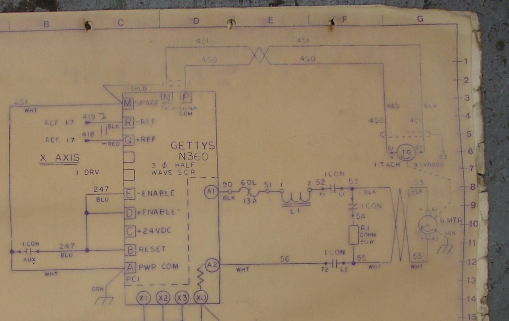
Can someone help me understand this part of the wiring? Sorry for the big image but I think it's necessary. As current flows through L1 it closes the two NO 1con contacts and allows the motor to run. If the drive stops and the motor is decelerating the two NO contact open and the BEMF is bled off through R1.
Two questions:
how does the current flow through L1 before 1CON is closed?
Should I retain this circuit?
I believe you are mis-interpreting the schematic, that looks to me like you have motor contactor called 1CON which applies power to the motor and also brings in the braking resistor in the off mode.
The coil L1 appears to be just an impedance match inductor.
It would be on its own and have no contact armature attached?
The coil for 1CON would be elsewhere and labeled as such.
Modern designs would not use 1CON in a servo application, but if retaining the drive, you should retain L1 .
Al.
CNC, Mechatronics Integration and Custom Machine Design
“Logic will get you from A to B. Imagination will take you everywhere.”
Albert E.
I agree with Al (no surprise there, he's the man
The way this basically has to work is that when the contactor is engaged, the motor wiring is connected to power. When it's disengaged, the motor is disconnected from power and connected instead to a braking resistor that dissipates the energy from the motor's inertia.
Without somewhere for the electricity to go from that, you'd burn out a fuse or your drive.
My own mill uses the Servo Dynamics drives, which include a circuit for dissipating servo braking current in a similar way.
So if you're keeping the drives, you need something that does what this circuit does.
Erik
Thanks guys. Out it goes. I'm not using the drives.
I see they are SCR drives, for bi-directional control they would have to be 4 quadrant drives.
4 quadrant drives are capable of dynamic braking I am surprised they would not have it on the Gettys drives.
In that era Fanuc & Mitsubishi initially used Gettys motors with their own design of 4 quadrant drive that included the dynamic braking.
But if I am not mistaken, this contactor is picked up the whole time during motion and only dropped out in E-Stop?
Al.
CNC, Mechatronics Integration and Custom Machine Design
“Logic will get you from A to B. Imagination will take you everywhere.”
Albert E.
It looks like the control put out an enable signal to a relay which in turn controlled the three contactors for the three drives.
Sounds right, I have only ever seen a contactor used like this used for the stop/start mode when it was a non motion control application.Originally Posted by will gilmore

Al.
CNC, Mechatronics Integration and Custom Machine Design
“Logic will get you from A to B. Imagination will take you everywhere.”
Albert E.
I've been struggling through learning Linuxcnc / hal / pncconf. Interesting but lots to learn.
Any one have info on how to properly implement estop and limits?
The machine has a chain of switches including x, y , z limits, motor overloads, low lube, etc.
I'll have one or two latching estop buttons.
In terms of estopping the motors this seems like a good idea:Support
I can use the 3 2 ohm 50W resistors that came with the mill to make a 6 ohm load dump resistor.
I'm thinking I'll use one output from linuxcnc to drive an enable relay which will allow AC power to the PS and send 5VDC to enable the drives.
Should I use a second NC contact on the estop in series with the limit switch chain as an input to linuxcnc?
If you are using O.T. L.S.'s in series, then normally these would go in a hard wired series E-Stop string which would include any other reasons for E-Stop, E-Stop P.B.'s etc.
You could put your controller in this string, also a contact on the final E-stop/Control relay would go back into the controller to advise of an external E-Stop.
This control relay would ultimately be responsible for dropping out servo and spindle power, if these components are each fed from a main contactor, then the power to all these contactor coils could be switched by the control relay, there are a few ways to do it, but ultimately the result should be the same.
In the case of the PC triggered E-stop, it also pays to have a watch dog timer output that indicates the health of the PC and system, Mach uses a oscillator signal that operates a charge pump or watch dog timer to achieve this.
You can get an idea from the original prints how this was hopefully done.
Al.
CNC, Mechatronics Integration and Custom Machine Design
“Logic will get you from A to B. Imagination will take you everywhere.”
Albert E.
Got it thanks. On the original prints everything goes in and out of black boxes so its hard to see the functionality of the chain.
I'm familiar with the charge pump in mach3. It looks like linuxcnc has a similar feature: LinuxCNC Documentation Wiki: About Charge Pumps . Does anyone know if this is already implemented in the the Mesa boards or do I need an additional board?

The mesa hardware his its own charge pump/ watchdog.
HOSTMOT2
sam
Thanks for the link. I'll read up.
I read the HOSTMOT2 page about watchdogs. It looks like the HAL file generated by pncconf already has the watchdog.
Wiring questions:
As Al recommending I'm making an estop string that includes estop pushbutton(s), the limit switches, low lube, and an enable relay controlled by LINUXCNC. This string will control an ESTOP relay that provide power to the spindle relays and servo power supply and will feedback to a fault input in LINUXCNC.
The AMC drives have a 5V TTL level inhibit input. The manual says "TTL level (+5 V) inhibit/enable input. Leave open to enable drive. Pull to ground to inhibit drive. Inhibit turns off all power devices." Should I use a NC contact on the enable relay to connect this to ground?
The drives also have a 5V TTL level fault output that goes high when the drives fault. It's also high when the drives are inhibited. Should I bring this into the estop chain somehow or use another input to LINUXCNC for a drive fault?
Grounding questions:
My cabinet has a big grounding block. The existing wiring keeps the different COMs (120VAC, 24VDC) seperate but all connected to the grounding block where the service ground comes in. Do I tie all grounds and commons to this block? Anyone have a link to grounding theory?