Tree Journeyman 320 B Retrofit - Page 2


Page 2 of 9 FirstFirst 12345 ... LastLast
Results 21 to 40 of 179

Thread: Tree Journeyman 320 B Retrofit

  1. #21
    Registered
    Join Date
    Apr 2007
    Location
    New York, NY
    Posts
    521
    Downloads
    0
    Uploads
    0

    Default


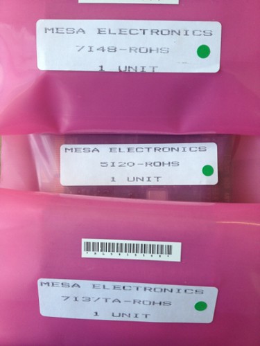
    Ta da!

    I found some AMC drives on ebay so I made a last minute switch to Mesa. I ordered the 7i48 instead of the 7i33.


  2. #22
    Member jsheerin's Avatar
    Join Date
    Aug 2008
    Location
    US
    Posts
    1166
    Downloads
    0
    Uploads
    0

    Default

    If they're Amp connectors, look on the front and back for a molded part number. A lot of times it will be there, but really small. Even if you just get the insert number, that would help. A full part number would be something like MS3106A22-14S. 22-14 is the insert number which describes the arrangement and number of pins. S is for socket (P is for plug), and the MS3106A part describes the rest of the connector. Mouser has them. If they're real expensive, I've found surplus ones on ebay for less, but that can be hit or miss.

    CNC mill build thread: http://www.cnczone.com/forums/vertical_mill_lathe_project_log/110305-gantry_mill.html


  3. #23
    Registered
    Join Date
    Apr 2007
    Location
    New York, NY
    Posts
    521
    Downloads
    0
    Uploads
    0

    Default

    Quote Originally Posted by jsheerin View Post
    If they're Amp connectors, look on the front and back for a molded part number. A lot of times it will be there, but really small. Even if you just get the insert number, that would help. A full part number would be something like MS3106A22-14S. 22-14 is the insert number which describes the arrangement and number of pins. S is for socket (P is for plug), and the MS3106A part describes the rest of the connector. Mouser has them. If they're real expensive, I've found surplus ones on ebay for less, but that can be hit or miss.
    Thanks! I had looked for the part number but it was there very tiny on the edge of the panel mount. Mouser has them for $2.81 and the socket contacts too.


  4. #24
    Registered
    Join Date
    Apr 2007
    Location
    New York, NY
    Posts
    521
    Downloads
    0
    Uploads
    0

    Default

    Ok. The last big thing I need to order is the power supply. I'm using AMC B30A8 servo drives which have a maximum of 80V. I'm looking at 1.5kva power supplies from Antek. Antek - Transformers - Grid View[]=1
    To complicate things further I have 208V service in this shop (measured at 213V)
    Should I get 80V 16.5A, 77V 19.5A, 70V 21.4A? At some point I will probably move somewhere with 230V service.


  5. #25
    Community Moderator Al_The_Man's Avatar
    Join Date
    Dec 2003
    Location
    Canada
    Posts
    24220
    Downloads
    0
    Uploads
    0

    Default

    Quote Originally Posted by will gilmore View Post
    Thanks Al. I wondering if I should try to reuse the speed sensor and control board. I'll leave it alone until I get the axes running.

    Any one know where I can buy these connectors? It would be handy to use them to break out the wires coming from each axis rather than cutting these up. They are Amphenol which I looked up but they make 1000s of different connectors.
    Those are Amp CPC style, just about everyone sells them. They are not MS types but much cheaper plastic versions.
    DigiKey, Mouser etc.
    You could use the sensor as a tach, the output is analogue.
    The 30A8's are cutting it a bit fine for those motors?
    Al.

    CNC, Mechatronics Integration and Custom Machine Design

    “Logic will get you from A to B. Imagination will take you everywhere.”
    Albert E.


  6. #26
    Registered
    Join Date
    Apr 2007
    Location
    New York, NY
    Posts
    521
    Downloads
    0
    Uploads
    0

    Default

    Quote Originally Posted by Al_The_Man View Post
    Those are Amp CPC style, just about everyone sells them. They are not MS types but much cheaper plastic versions.
    DigiKey, Mouser etc.
    You could use the sensor as a tach, the output is analogue.
    The 30A8's are cutting it a bit fine for those motors?
    Al.
    I haven't thought / learned much about the spindle speed sensing in EMC. I know it supports rigid tapping with some kind of positioning input.

    B30A8: 80VDC 15A continous. I thought it seemed like a good match to the motors. Not true?


  7. #27
    Community Moderator Al_The_Man's Avatar
    Join Date
    Dec 2003
    Location
    Canada
    Posts
    24220
    Downloads
    0
    Uploads
    0

    Default

    IRC your motors are around 80vDC?
    These drives shut down at 86v so it does not give much room for PS or BEMF tolerance?
    Al.

    CNC, Mechatronics Integration and Custom Machine Design

    “Logic will get you from A to B. Imagination will take you everywhere.”
    Albert E.


  8. #28
    Member samco's Avatar
    Join Date
    Jul 2003
    Posts
    1753
    Downloads
    2
    Uploads
    0

    Default

    You need an encoder on the spindle for rigid tapping with A,B and Z channels.

    sam

    Quote Originally Posted by will gilmore View Post
    I haven't thought / learned much about the spindle speed sensing in EMC. I know it supports rigid tapping with some kind of positioning input.

    B30A8: 80VDC 15A continous. I thought it seemed like a good match to the motors. Not true?


  9. #29
    Registered
    Join Date
    Apr 2007
    Location
    New York, NY
    Posts
    521
    Downloads
    0
    Uploads
    0

    Default

    Quote Originally Posted by Al_The_Man View Post
    IRC your motors are around 80vDC?
    These drives shut down at 86v so it does not give much room for PS or BEMF tolerance?
    Al.
    Ok. Should I choose a slightly lower PS voltage to provide some room?


  10. #30
    Registered
    Join Date
    Apr 2007
    Location
    New York, NY
    Posts
    521
    Downloads
    0
    Uploads
    0

    Default

    Quote Originally Posted by samco View Post
    You need an encoder on the spindle for rigid tapping with A,B and Z channels.

    sam
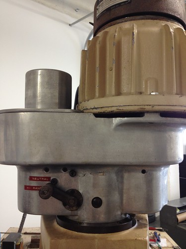
    The speed sensor is not located on the axis the spindle. It is in the back of the aluminum cylinder on the top left of this picture. I'm not sure how the high / low gears work but it looks like the censor would be on the motor side of the gears.


  11. #31
    Community Moderator Al_The_Man's Avatar
    Join Date
    Dec 2003
    Location
    Canada
    Posts
    24220
    Downloads
    0
    Uploads
    0

    Default

    You may need to go lower on PS or higher on drives, unless you already have them.
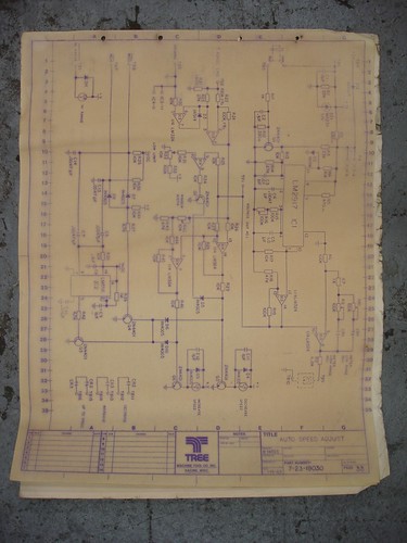
    The print does not show the output of the LM2917, but I suspect it may have gone to an analogue (moving coil) meter?
    Al.

    CNC, Mechatronics Integration and Custom Machine Design

    “Logic will get you from A to B. Imagination will take you everywhere.”
    Albert E.


  12. #32
    Registered
    Join Date
    Apr 2007
    Location
    New York, NY
    Posts
    521
    Downloads
    0
    Uploads
    0

    Default

    I'm reading through the AMC drive information.

    http://www.a-m-c.com/download/manual...tallManual.pdf - Manual
    http://www.a-m-c.com/download/support/an-007.pdf - Running brushed motors
    http://www.a-m-c.com/download/datasheet/b30a8.pdf - Data sheet

    These drives can take many types of inputs and run in many modes. I am going to use +/- 10V analog input with current (torque) mode?

    There is also a tach on the motor and tach wires coming into the cabinet that were hooked up to the original drive. Do I leave this disconnected?


  13. #33
    Community Moderator Al_The_Man's Avatar
    Join Date
    Dec 2003
    Location
    Canada
    Posts
    24220
    Downloads
    0
    Uploads
    0

    Default

    Yes, you don't use the tach in torque mode.
    I just take the brushes out of the tach to avoid problems.
    Al.

    CNC, Mechatronics Integration and Custom Machine Design

    “Logic will get you from A to B. Imagination will take you everywhere.”
    Albert E.


  14. #34
    Registered
    Join Date
    Apr 2007
    Location
    New York, NY
    Posts
    521
    Downloads
    0
    Uploads
    0

    Default

    Quote Originally Posted by Al_The_Man View Post
    You may need to go lower on PS or higher on drives, unless you already have them.
    The print does not show the output of the LM2917, but I suspect it may have gone to an analogue (moving coil) meter?
    Al.
    I already have the drives. I saw them on ebay and bought them. Serves me right for buying with out asking the forum. What size PS do you recommend?

    The LM2917 was part of a larger speed control board that turns a 120V motor that controls the variable speed in the head.


    tree manual 018 by Gotham Machine, on Flickr


  15. #35
    Community Moderator Al_The_Man's Avatar
    Join Date
    Dec 2003
    Location
    Canada
    Posts
    24220
    Downloads
    0
    Uploads
    0

    Default

    Out of the P.S. options I would go with the 70v.
    The spindle drive used it as a digital to analogue tach.
    Al.

    CNC, Mechatronics Integration and Custom Machine Design

    “Logic will get you from A to B. Imagination will take you everywhere.”
    Albert E.


  16. #36
    Registered
    Join Date
    Apr 2007
    Location
    New York, NY
    Posts
    521
    Downloads
    0
    Uploads
    0

    Default

    Quote Originally Posted by Al_The_Man View Post
    Out of the P.S. options I would go with the 70v.
    The spindle drive used it as a digital to analogue tach.
    Al.
    The Antek power supplies come in 80VDC, 77VDC, 73VDC, 70VDC, 67VDC etc. Am I correct in thinking that an unregulated PS will produce somewhat lower output DC voltage when run on 208VAC input rather than 203VAC input? So all the DC voltages would be ~10% lower?

    EDIT: 203VAC above should be 230V. oops

    Last edited by will gilmore; 02-01-2012 at 07:41 PM.


  17. #37
    Community Moderator Al_The_Man's Avatar
    Join Date
    Dec 2003
    Location
    Canada
    Posts
    24220
    Downloads
    0
    Uploads
    0

    Default

    ?? it will be higher on 208 rather than lower over 203v!
    Output voltage is directly proportional to the transformer ratio, input to output.
    What have you actually measured, BTW?
    Al.

    CNC, Mechatronics Integration and Custom Machine Design

    “Logic will get you from A to B. Imagination will take you everywhere.”
    Albert E.


  18. #38
    Registered
    Join Date
    Apr 2007
    Location
    New York, NY
    Posts
    521
    Downloads
    0
    Uploads
    0

    Default

    OOPS. I intended to write 230VAC not 203VAC.

    I have measured the voltage at the panel to be 213VAC.

    I believe the power supplies are rated for 230V input. If I use a 230VAC/80VDC on my 213VAC circuit I will end up with (208/230)*80 or 74VDC right?

    Sorry for the confusion. Thanks for your help. You are very generous with your time and knowledge!


  19. #39
    Community Moderator Al_The_Man's Avatar
    Join Date
    Dec 2003
    Location
    Canada
    Posts
    24220
    Downloads
    0
    Uploads
    0

    Default

    or 75.29v on your 213
    Or close enough
    Al.

    CNC, Mechatronics Integration and Custom Machine Design

    “Logic will get you from A to B. Imagination will take you everywhere.”
    Albert E.


  20. #40
    Registered
    Join Date
    Apr 2007
    Location
    New York, NY
    Posts
    521
    Downloads
    0
    Uploads
    0

    Default

    So is that enough of a buffer?


Page 2 of 9 FirstFirst 12345 ... LastLast

Tags for this Thread

Posting Permissions

  • You may not post new threads
  • You may not post replies
  • You may not post attachments
  • You may not edit your posts
  •  


About CNCzone.com

    We are the largest and most active discussion forum for manufacturing industry. The site is 100% free to join and use, so join today!

Follow us on


Our Brands

Tree Journeyman 320 B Retrofit

Tree Journeyman 320 B Retrofit