I never left. Been here the whole time.
Color choices sound excellent. Look forward to seeing it dressed up.


Hi Lee, Welcome back :cheer~Originally Posted by LeeWay

Yes. I chose the colorway several days ago. I want to use Orange and Dark Gray as the major colors for my machines. I have ordered the paint sample now. Double component resin paint type. I had used such paint before and should be best for machines.
I will do the putty works very soon also and then I guess I will receive the paints in 3-4 days so I can paint the machine.
Thank you again. And yes, I'm sure the machine will look not bad.
www.skyfirecnc.com
Email: info@skyfirecnc.com; Skype: skyfirecnc
I never left. Been here the whole time.
Color choices sound excellent. Look forward to seeing it dressed up.
Lee
Yes man, I can imagin the picture as you described. Trust me, My bigger CNC I used to mill the casting iron parts looks much much more worse than yours now..
www.skyfirecnc.com
Email: info@skyfirecnc.com; Skype: skyfirecnc
I almost want to paint it right now... but have to adjust the accuracy firstly, and putty works may take 1-2 day to wait it dry, and second putty work..
But I'm sure we will see the coated machine within 4-5 days!
www.skyfirecnc.com
Email: info@skyfirecnc.com; Skype: skyfirecnc
Fantastic
Thanks man. Welcome any inputs here
www.skyfirecnc.com
Email: info@skyfirecnc.com; Skype: skyfirecnc
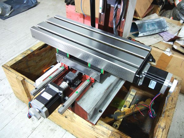
Hi guys. I have done many small works today.
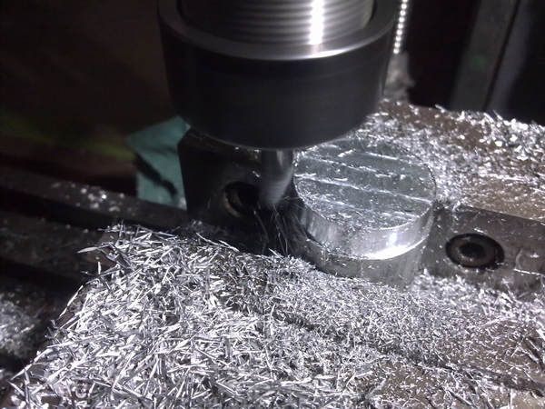
Firstly I planned to install the motors firstly to make the axis move convinient because the motors have the small handwheels behind. To install the motor in the right position, I milled a smll locating coupler between the ballscrew end and the motor bracket. It's a simple AL part I machined with CNC control.
Fit in very well:
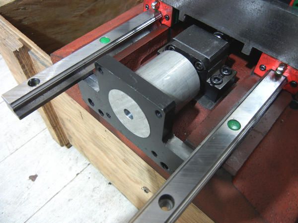
Locating the bracket:
After locating the bracket I could drill the screw holes at the right postion so the stepper motors can drive the ballscrews more smooth with shaft couplers.
www.skyfirecnc.com
Email: info@skyfirecnc.com; Skype: skyfirecnc
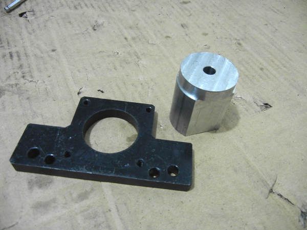
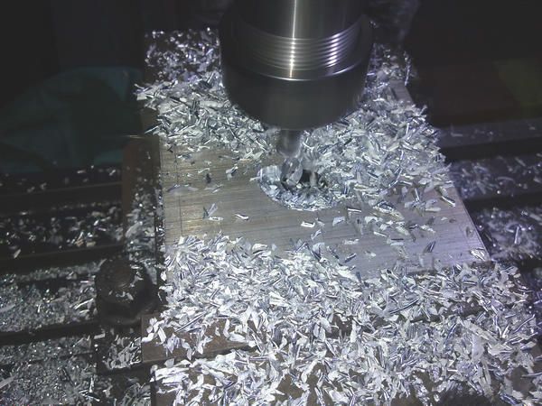
Next was the spindle motor mount. I had planned to use the steel board as standard but has no fitfull material in hand. So I made this one with aluminium too.
Still simple CNC milling firstly:
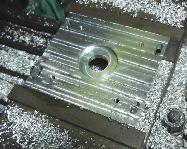
One side finished:
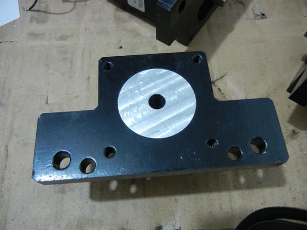
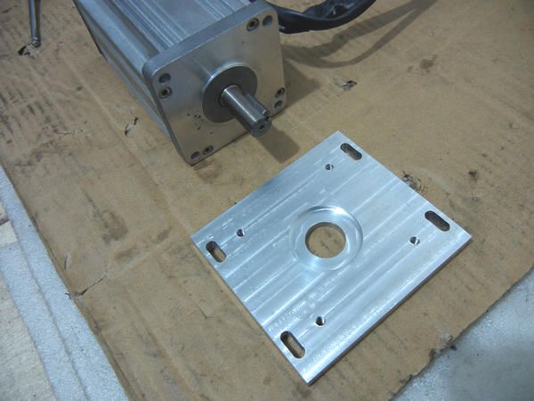
All finsihed. seem nice
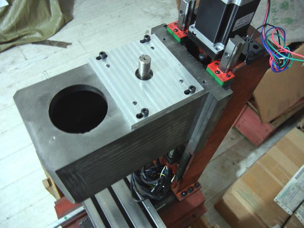
installed to the head and make the spindle motor having some adjustable distance:
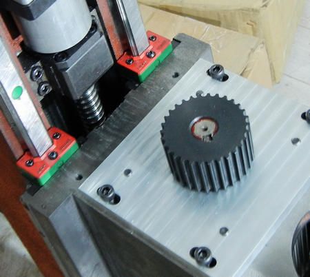
After installing the spindle motor, I added the timing pulley to the shaft. This was an easy step also.
www.skyfirecnc.com
Email: info@skyfirecnc.com; Skype: skyfirecnc
Hi skyfire, I think your machine would look good in red, not bright pillar box red but a deep red like old blood...LOL....maybe with a slight hint of Maroon in it.
Just looked at the 4th photo in post #128 and the red colour looks quite good.
BTW, I have been puzzling over something.......the X axis rails stick out in front of the slide....is this because the rails were too long and you didn't want to cut them short?
Also I see you are using a toothed drive pulley for the spindle....would this not be better using a Poly Vee type belt......there is a tendency for cyclic vibration to be imparted to the cutter and hence the job with toothed belts........I also believe that toothed belts don't last long at high speeds, but I might have misread this.
Also while on the subject of spindle drives, you mentioned that a variation would be needed to allow different drive ratios to be explored......in that case I would fit a Poly Vee type pulley and use a taperlock for the spindle and motor attachment which makes changing and removing pulleys very easy, but still maintains perfect balance and security of drive.
PS, your grinding wheel needs dressing....the finish on the table front is shocking...post #115 photo #4
Ian.
Hi my friend, thank you for new comments here!
Yes, I can imagin the dark red color...That would be coolI have ordered some orange color paint sample and will arrive in a few days I think. I think maybe I will make several different colorways then to get the best choice, haha..
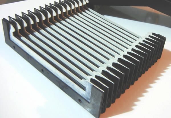
The rails of X, Z are all some longger than traveling needs. I made this intentionally. The porpose is to add the axis covering and the longger rail slots can hold the covers tight in case they plump up when compressed. Actually I just ordered the covers with some sketch and may avaliable after one week.
just like the one used on another machine:
I understand the comment on the belt and pulley issue. I chose the HTD-5M type timing pulley for this spindle system. The HTD type is very common on industrial VMC spindle units and run very smooth because the teeth is round type. So will not generate the vibration. Another small consideration is that the pulley structure is more simple than using V type belt system. I don't need special tighten structure of the motor part. The ratio changging structure you mentioned should be the most stardard one for spindle system. But that will need some special ordered pulley and associate parts may take some long time. So, I would like to try some easy way for me now.
About pulley exchanging system, I'm planning small updates on the pulley and make it can be fatened on the shaft end(need thread on the center of the shaft end) so the pulley can be easily exchangged.
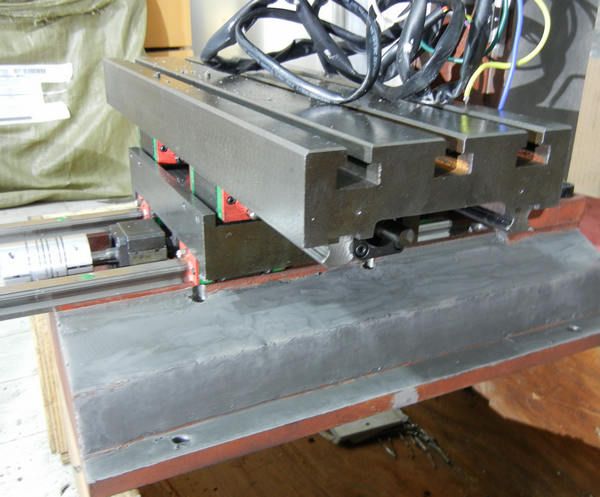
Yes, very sharp observing...the grinding works of the worktable is not very good. The reason is that almost every machining supplier have closed for CNY. I don't have a grinding machine so this work is done in a road side small shop... That's the only one I can get for this prototype. Did you see the top of the worktable without scarly marks? I re-ground it manually with a big oilstone
Now I'm doing the putty works...Another dirty work..haha. This just the first putty, so looks not nice. The casting surface is not bad, so it will save me many strength. I'm using some fast dry putty here, just save time.
Last edited by Skyfire; 02-19-2013 at 11:49 PM.
www.skyfirecnc.com
Email: info@skyfirecnc.com; Skype: skyfirecnc
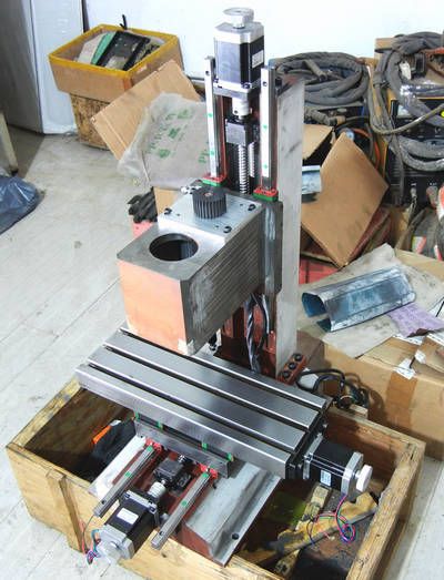
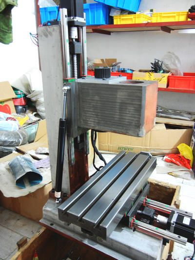
Hi guys. I've installed all of the motors now. no problem in this part.
Then I finished the putty works and ground the surface to be smooth. So totally the machine is ready for painting.
Then the gas spring has been installed. so the Z traveling much easier now. should be better balance of up/down after spindle unit installed.
www.skyfirecnc.com
Email: info@skyfirecnc.com; Skype: skyfirecnc
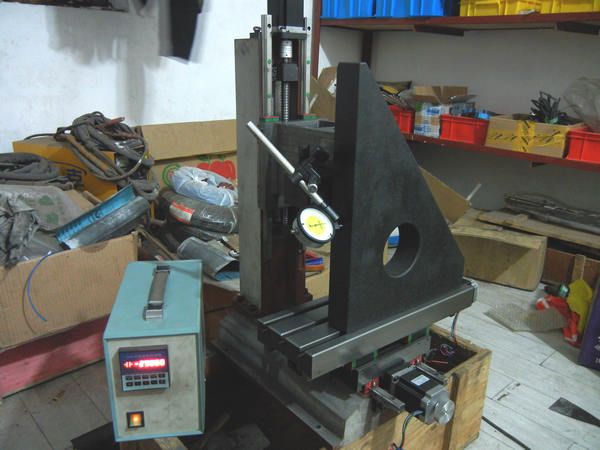
The following work of accuracy adjusting is most important. Most of this part need work with the dialgage and stone ruler used former. I connected a stepper motor controller I DIYed before and make the adjusting quicker. I took only one picture during the adjusting. other steps were pretty similiar.
Now I show the last accuracy testing report:
(all error within full travel distance)
X travel plate error: 0.02mm
Y travel plate error: 0.01mm
X-Y perpendicularity: 0.01mm
Z-X perpendicularity: 0.01mm
Z-Y Perpendicularity: 0.01mm
Totally I'm very satisfied with the error result. I can test the spindle to worktable perpendicularity now. so have to wait the spindle unit.
I'm sure if the grinding works of the worktable could be better, the X travel error should be within 0.01mm also. I could also do some manual fixing work with oilstone also to make it <0.01mm,,, but it will take some long time. so I just leave it as it is now.
Nex I will just dissamble the machine and paint the main structure. And then assemble it again. I will measure the errors again when assembling again to make sure of same--or even better---just if I'd like to cost more time on it
www.skyfirecnc.com
Email: info@skyfirecnc.com; Skype: skyfirecnc
Hi Sky, it's nice to have the right tools to do the testing......not many people have access to a granite reference square or even a big square of known accuracy.........I could not think of any other way possible to test your results, unless one went to the extraordinary lengths of making a Camel back square (in threes) to test for flatness and straightness etc.
I suppose that anyone else doing a similar build and who wanted to achieve and test squareness without going out and paying a huge amount of money for a reference square would have to make a cylindrical square if they had the material and a lathe big enough to do it.
As a matter of interest I would like to see the final build cost compared to buying in and converting a similar size mill, even though a conversion job does not have linear slides.
One important aspect I will be watching for is the performance of the linear rails while milling steel compared to a similar mill, like the SX3 or G0704 etc which have dovetail slides.
If the linear rails can perform well for stability while maintaining rigidity when cutting steel then the dovetails used on similar mills can be removed (if possible) and a true full conversion achieved.....(never mind the cost....LOL).....the cost comparison to this build will be interesting, especially as this mill is a linear rail build from day 1.
I had an interesting conversation with a friend of mine and the topic of mill construction came about and the difficulty anyone would have making a Tee Slot table....he said that if he was going to make a mill from scratch he would spark erode the Tee slots in the table after milling the long slots with an end mill.....wow, that would take some sparking.
This is some interesting ride.
Ian.
Hi buddy, glad to have your inputs again. Yes, I think this is the best way I can have to make the machine most accurate now. You know there will be the best measurement with a laser interferometer but. ..that's really far from my achieve now. A stone referance square should be enough for this level machine. But currently, I could just measure and make sure of the flatness and straightness of the machine body structure. The last cutting accuracy will depend on more aspects when getting to the 0.01mm level. The ballscrew accuracy level, the linears level, bearings level etc. They must match the accuracy requirement and can not have any short board. For this prototype I will not push it too high. just make sure of 0.02mm total error.
It's a smart methord to cut a real cylinder and then measure it on a good lathe to test it's round ness and top end flatness. then we will know the basic features of the CNC too. And the tool diameter must be fixed because normally it will has about 0.01-0.02mm error. And at least one cycle of finishing cut is quite necessory too to get the real result.
As to the cost issue, I don't have the accurate calculations now. but I guess it will not be more expensive than buying a benchtop mill and then buy conversion parts etc to replace many manual ones, let alone maybe much more labor works and maybe extra machining costs etc. So if you want to covert a real good CNC, the last cost will be definately more than your original calculating.
Long time ago I had a SIEG SUPER X3 and converted to CNC and then used much. The mark accuracy is 0.03mm from SIEG factory( I had visited SIEG production process 5 years ago and talked with their CEO and chief engineer). The real cutting accuracy is between 0.03-0.05mm with C7 class ballscrews during my personal experience. I'm sure some one can do better now.
But I don't know the perpendicular of it at all(does any one have measureed it?) because I don't have the stone square then. So I think the 0.03mm accuracy is only the single axis traveling error. So, can I say mine is 0.01 or 0.02mm accuracy without perpendicular adjustment? even it's more than 0.10mm?
And about the linear rail performance, I had some succeful experiments on a bigger CNC and proved to be no problem. Actually I think the bigger concern of steel cutting is to have a good mill tool and avoid machine shaking.. That's quite important here. I will definately test the real works then and try to upload some videos here.
The goodness of linears is to support both precision and rapid movement together. There always has a solution even compare the stiffness
to the dovetails. Using enhanced length linear blocks, or even three blocks for one rail; or even pin roller type linears will solve this perfectly... of course, cost issue here
But dovetail has its natural problems. If you want more accuray, must lock the rails tight, then axis driving, rapid speed, lurication and wearing issue come out. If anyone has noticed the dovetails of machines like X3, you will find the dovetails are finishing milled, and the adjusting steel boards are ground. That's not serious method. The steel board should be scraping type for better lubricating and lower wearing.
...wow, I couldn't image how much spark would take for T SLOTs.. why not buy a T slot mill tool? very cheap thing.. but it must be the most beautiful T slots here
www.skyfirecnc.com
Email: info@skyfirecnc.com; Skype: skyfirecnc
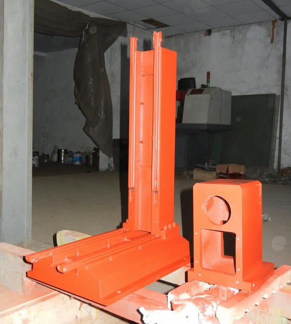
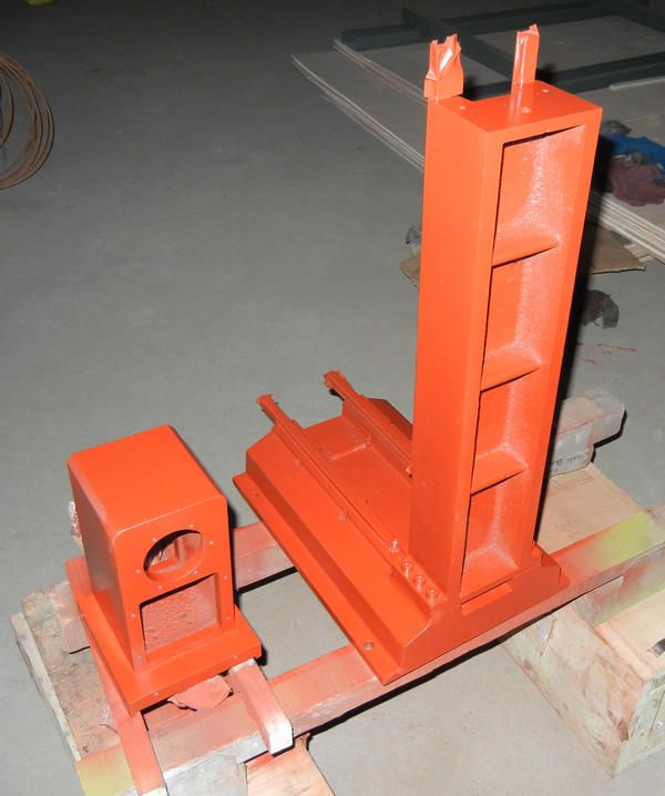
Now the painting process... really costed me much time for putty works these two days.
Firstly, the antirust bottom paint: the formal paints will be done after the antirust paint dry. I removed all other parts and covered the rails with some tapes.
looks much more beautiful now
www.skyfirecnc.com
Email: info@skyfirecnc.com; Skype: skyfirecnc
Awesome thread Skyfire! It looks like your machine is going to be very nice once you are finished, thank you very much for sharing it with us.
How serious are you about manufacturing these to sell? I think there would be a huge market for them if you could keep the price competitive with the other "turn-key" benchtop CNC machines, $5,000-$9,000.
Hi DRock, thank you for your input~
I received many interest mails these days and seems such benchtop machines have some market here as you said...so,, yes, I'm considering the marketing plans serious recently. I have some CNC parts resources also, so I think I should be able to do somthing in this area.
Yes. The price issue is the important concern here. I have not got the last cost list now, but I'm sure the price will not reach the range you mentioned of >$5000. It must be much lower than that. I'm considering set up a website for my project introduction and sale works now... Do you think it will be a good plan?
And, I'm also thinking maybe should have some diffent versions because some guys want longger worktable to reach about 10" X traveling. and some want full enclosures but others don't want enclosure but only electric box with control pannel on machine body.
I really hope you guys can give some advises on such issues~~ cheers~~
Skyfire
www.skyfirecnc.com
Email: info@skyfirecnc.com; Skype: skyfirecnc
This is my favorite thread on the forum.
I love seeing your updates.
For the right price I would be very keen to buy one of these.
R
If you do customization, the time and headache can go up dramatically. I would offer two basic versions like tormach and if the market has good reception, then I would offer custom kits to add. There is also the matter of shipping, to make any economic sense you need to ship quite a few units.
Its good idea. You can sell machine part such as spindle, milling head, etc.I'm considering set up a website for my project introduction and sale works now... Do you think it will be a good plan?
 Posting Permissions