New Machine Build Show how to build a CNC machine from the very beginning to the end - Page 6


Page 6 of 183 FirstFirst ... 34567891656106 ... LastLast
Results 101 to 120 of 3652

Thread: Show how to build a CNC machine from the very beginning to the end

  1. #101
    Member handlewanker's Avatar
    Join Date
    Sep 2006
    Location
    Australia
    Posts
    6463
    Downloads
    0
    Uploads
    0

    Default

    Hi skyfire, I just came across this thread while browsing for gantry mill build designs as I've got a fixed gantry mill design in mind I'd like to have a go at, and noted the motor drive comments re-the speed and torque when running at the low end.

    At the moment I'm re-motoring a small lathe to run from a 3/4 HP 3ph 3,000 rpm motor and using a VFD instead of the more common vee pulley drive.

    So, the motor will be required to be run at the low end some times under VFD control, and as the motor will over heat when run for long periods like this I'm reducing the input to 1:2 reduction giving me 1,500 rpm from the motor at the top end and as the VFD can double this to 3,000 the top speed won't suffer while the motor can still revolve at sufficient speed at the low range to keep it from overheating.

    One question as regards to the design of your mill....is it better to design with castings for rigidity to enable heavy cutting at lower speeds or to design with steel tubing for lighter cuts but many under CNC control, like the UMC-10 design by David De Caussin of Fadal fame?

    I know that rigidity is a prime factor in any machine, but many light cuts as opposed to few heavy cuts does give the machine design an area to explore with modular material construction using lighter gauge steel materials and welding for construction.

    I have always been of the opinion that converting an existing table top mill that has dovetail slides is only half way to doing a CNC machine conversion due to the drag that Vee slides have over Linear types.

    Seeing your castings and the subsequent milling of the linear slide seats, I would have to think that to do a conversion job with an existing mill, like the Super X3 etc, it would be far better to mill away the dovetail slides and refit linear slide rails in their place....if the existing X3 castings allowed this.

    This may already have been done, but I haven't seen any build thread doing this so far.

    Just fitting ball screws in place of the Acme threads still leaves you with tight slides and missed steps or loose slides and lost tolerances.

    The drawings of the machine in the first few posts did not open, so I could not see the design and only got the general layout from the finished castings before maching.

    It will be interesting to see how the head design turns out, especially the spindle bearing layout....looking good so far.

    Will this go to a manual or air draw bar?
    Ian.


  2. #102
    Registered
    Join Date
    Jan 2008
    Location
    USA
    Posts
    52
    Downloads
    0
    Uploads
    0

    Default

    Quote Originally Posted by handlewanker View Post

    So, the motor will be required to be run at the low end some times under VFD control, and as the motor will over heat when run for long periods like this I'm reducing the input to 1:2 reduction giving me 1,500 rpm from the motor at the top end and as the VFD can double this to 3,000 the top speed won't suffer while the motor can still revolve at sufficient speed at the low range to keep it from overheating.
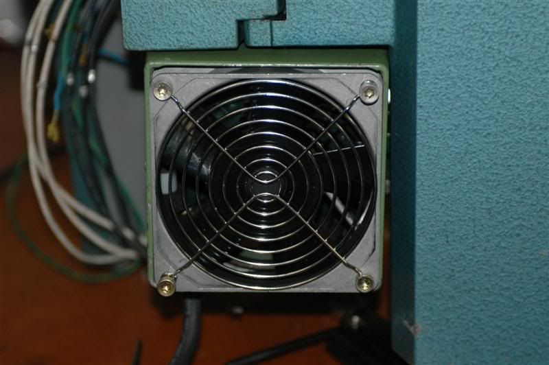
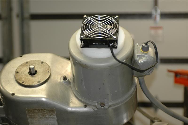
    If you are concerned with overheating, take the fan off the motor and replace it with a 4 inch computer type fan of suitable power. You can control the fan from the VFD relay. Remember... at 1/4 base speed the motor is only capable of 1/4 max power (roughly) so the heating effect is 1/4 (roughly). If you boost low torque or use DC injection for braking, consider placing thermisters in the motor and wiring them to the vfd.

    Like this (emco lathe)


    or this (BP mill)


    On my latest mill conversion I haven't bothered and I use the heck out of it (CNC). The 3hp motor barely gets more than warm at low rpm.


  3. #103
    Registered Skyfire's Avatar
    Join Date
    Jul 2011
    Location
    Afghanistan
    Posts
    441
    Downloads
    0
    Uploads
    0

    Default

    Quote Originally Posted by lakeside53 View Post
    Not sure why you think the 0.75hp AC servo motor would weight 20kg. I see the weight for modern 750 watt (1hp) AC servo motors (3000-6000rpm ) at 2.9 kg... And these are rated for 3.5X peaks. Look up the data for a Mitsubishi HF-KP73A.

    I think there is some confusion. The AC Servos I'm talking about are BLDC.

    My spindle motor is a BLDC AC PM servo - a not a stock induction motor run with a VFD, and is about 1/4 - 1/8 of the weight of the similar induction motor. It's older (Emerson MGE4120 but capable of 2X torque for sustained peaks from zero to 3000 rpm, but for CNC lathe applications I never design with peak capability in mind. The problem with using "peaks" is that you cannot sustain many peaks back to back (look at the duty cycle data), and that's what CNC machines do.

    Even if you can run peak of 4X sustained at low speed (you cannot for long -expecially with repetitive opertations), that's still only a 0.2hp PEAK motor at 200hz. Of course, if that meets your needs, that's fine.

    I'm also using AC servos (BLDC) for the X and Z axis - 200 and 400 watt respectively (Mitsubishi HF-KP23 and HF-KP43). These are small and have flat torque/speed curves. Unlike steppers they have close to 100% torque at 100% rpm (3000 rpm in this case, but are allowed to be run up to 4500). Of course, they cost a heck of a lot more! These are driven from MR-J3-xxA AC servo amps (which I'm buying used... crazy expensive new).
    Hi, thank you for more details. I think we made confusion on AC motor. The AC motor I was talking about is just common industrial ones, not AC servo type. The AC servo ones are just similiar with BLDC, but just different work theory--one is induction; another is permanent magnent. But people often call BLDC a AC SERVO generaliazed.

    So when I'm talking about the common AC motor, they are just big, heavy as I said. actually I have one in hand. I think I will not go to AC servo type ones, because It will cause cost rise much just like you side. I'm sure if BLDC get more spread, it will be better cost control. But the last limitation of BLDC is rare earth material problem.

    I get that you are actually using the BLDC system now. It has confused me because you used "VFD". Generally I will say just BLDC DRIVER, and when talking about VFD, it will related o induction AC motor. So maybe this caused some misunderstanding too.

    And about the "peak" issue, it doesn't mean any manchine could maintain peak conditions long time in a real work. But peak work capacity really means much especially at very low speed. on this point I think mill is different than lathe. The cutting on a lathe is much more smooth than on a mill. The cutting is more like "pulse" on mill. And our mill spindle and motor are mostly inertia ones. So during our tests, the driver showed many time "peak"s in low speed but hard cutting tests. of course, very short, no longger than a second.

    www.skyfirecnc.com
    Email: info@skyfirecnc.com; Skype: skyfirecnc


  4. #104
    Registered Skyfire's Avatar
    Join Date
    Jul 2011
    Location
    Afghanistan
    Posts
    441
    Downloads
    0
    Uploads
    0

    Default

    Quote Originally Posted by handlewanker View Post
    Hi skyfire, I just came across this thread while browsing for gantry mill build designs as I've got a fixed gantry mill design in mind I'd like to have a go at, and noted the motor drive comments re-the speed and torque when running at the low end.

    At the moment I'm re-motoring a small lathe to run from a 3/4 HP 3ph 3,000 rpm motor and using a VFD instead of the more common vee pulley drive.

    So, the motor will be required to be run at the low end some times under VFD control, and as the motor will over heat when run for long periods like this I'm reducing the input to 1:2 reduction giving me 1,500 rpm from the motor at the top end and as the VFD can double this to 3,000 the top speed won't suffer while the motor can still revolve at sufficient speed at the low range to keep it from overheating.

    One question as regards to the design of your mill....is it better to design with castings for rigidity to enable heavy cutting at lower speeds or to design with steel tubing for lighter cuts but many under CNC control, like the UMC-10 design by David De Caussin of Fadal fame?

    I know that rigidity is a prime factor in any machine, but many light cuts as opposed to few heavy cuts does give the machine design an area to explore with modular material construction using lighter gauge steel materials and welding for construction.

    I have always been of the opinion that converting an existing table top mill that has dovetail slides is only half way to doing a CNC machine conversion due to the drag that Vee slides have over Linear types.

    Seeing your castings and the subsequent milling of the linear slide seats, I would have to think that to do a conversion job with an existing mill, like the Super X3 etc, it would be far better to mill away the dovetail slides and refit linear slide rails in their place....if the existing X3 castings allowed this.

    This may already have been done, but I haven't seen any build thread doing this so far.

    Just fitting ball screws in place of the Acme threads still leaves you with tight slides and missed steps or loose slides and lost tolerances.

    The drawings of the machine in the first few posts did not open, so I could not see the design and only got the general layout from the finished castings before maching.

    It will be interesting to see how the head design turns out, especially the spindle bearing layout....looking good so far.

    Will this go to a manual or air draw bar?
    Ian.
    Hi, thank you for many inputs. I think your idea on solving the over heat issue is great. And Lakeside53's suggestion should helpful to solve the thermal problem.

    The question of Why casting? is the very basic qestion on machine building. I understand mostly, we will use the bechtop mill just for some light cuttings. So from this point of view, steel materials, aliminium materials are all OK to build a CNC just if thick enough. And many guys did this way and their machine work seem no problem.

    But the point of casting structure is not just rigidity. For a CNC machine, it means more about precision from several aspects.

    1. casting structures are made a whole without welding and bolts. This means much about precision. The welding will genearte huge inner stress and make the machine structure transform fast or slowly with time. I'm sure if you build a CNC today with welding, and adjusted to zero error traveling, tomorrow it will not be zero any more. So basicly, the whole welded machine is not stable. you don't know what the last accuracy will be.

    Even the castings has initial inner stress too. It must have some rest time or heat treatment to eliminate the most part of the stress before we use them to build machines. But overall, much much stable than welded structure.

    structures with bolts are even more weak. Maybe no much inner stress than welded structure, but don't think it will never transform. One time heavy cutting or tool impact may cause the unrecoverable precision loss.

    one way to make the welded structure much more stable, it's heat treatment. It will work. but I don't think most the current CNC builds this way did this.


    2. Other small reasons. For example, the casting iron of HT series have some good features in microcosmic structure to help eliminate the shakeness of cutting, this will also mean something in precise cutting. The machine shakeness will be a big problem then.

    I think your thought about the convertion of a mill should be workable. But the convertion from dovetails to linears maybe not that easy. you maybe need to rebuild the whole saddle.

    I had disassembled a SX3 machine to every small part and had used it for some time, I converted it to CNC too. The total accuracy is about 0.05mm.

    Yes. I think I will be able to show the spindle box very soon. This will be the last big part machining after several days.

    My current spindle design is a manual one now. I don't think air draw bar will be necessory for such a small benchtop CNC. we can not use any industrial air drawbar for they are huge and expensive. Or ISO tool system for electric spindles, basiclly I think the current build is more of a mill.

    A special development of a air drawbar system with a special designed spindle unit could be a way, but I prefer to leave it as a further option in future.

    And BTW, I will make the spindle unit exchangeable between mill spindle system and high speed electric spindle system. So we can do both mill and carving works on a same machine.

    Welcome any other comments! cheers~

    Last edited by Skyfire; 02-11-2013 at 09:44 AM.
    www.skyfirecnc.com
    Email: info@skyfirecnc.com; Skype: skyfirecnc


  5. #105
    Member handlewanker's Avatar
    Join Date
    Sep 2006
    Location
    Australia
    Posts
    6463
    Downloads
    0
    Uploads
    0

    Default

    Hi, thanks for your enlightenment regards to the casting.......I have been looking at the UMC-10 mill of David DeCaussin where he used various sections of heavy walled square tube to arrive at his design.

    I quite agree with the problem with welding and the aspect of later movement from inbuilt stresses, but I have been using a Multiplaz 3500 plasma welder (designred in Russia, made in China) on various projects with success and I think the characterisics of the plasma weld are totally different to stick welding, which for a build using heavy wall square tube, you would normally have to use.

    The plasma weld is a fusion type, similar to a gas welder where the metal is melted at the joint and fused together, unlike a stick welder where the sudden and intense rise in heat as the arc forms the melt zone and subsequent cooling once the arc has passed creates stresses that progressively get locked into the joint.

    At this moment in time I'm watching all details of your build with great interest.

    I'm not a great fan of cast iron machining, having done much of it during my occupation as a fitter and turner before I retired, and the mess it creates makes cleaning the workplace and machinery a nightmare......everything gets a coating of graphite and you can taste it for hours afterwards...LOL.....and it gets into your skin big time.

    I see you mentioned that a manual draw bar would be fitted......does this mean you will be driving the spindle with a belt drive to one side ?

    What will the weight of the Z axis arrive at once fitted with motor?

    Making the head casting move instead of the quill has always been a problem with inertia for fast Z travel like pecking in a drill cycle even when compensated with springs or counterweight and moving the head casting with motor attached gives you a lot of weight.

    On the topic of an auto tool changer, I was looking at the Levil Industries mill the W400, and they have a very simple method where the tools are held in a rack on the end of the table and the head which moves (table is fixed) selects the tools as required by moving over them....very simple.....you can see it working on Utube.

    I believe the tooling system has an R8 short taper with an air drawbar.
    Ian.


  6. #106
    Registered
    Join Date
    Jan 2008
    Location
    USA
    Posts
    52
    Downloads
    0
    Uploads
    0

    Default

    Quote Originally Posted by Skyfire View Post
    The AC servo ones are just similiar with BLDC, but just different work theory--one is induction; another is permanent magnent. But people often call BLDC a AC SERVO generaliazed.

    .

    Actually... today they (the type I'm taking about) are both permanent magnet As the cost of the AC servo amp falls (high only because of limited numer of manfs and industrial orientation), they will beome the common standard (if the rare earth supply isn't contrained by politics and profit motives!).

    I'm surprised that you find milling loads to be "peaky" and can design the machine to work in that range. Sure, I can see that with small or intermittent cuts, but continuous tool paths provide constant load to the spindle. I watch the spindle current on my cnc BP and it is very constant when hogging out, with some operations taking 5-10 minutes between pauses. I can even see the effects of tool wear (spindle load rises for the same speed/feed) and get a good indicator when to change. By using "peak" as a design criteria, won't you have to rate your machine differently for different operations? Does you servo amp keep track of the peak and duty cycle useage (mine does), and fault or error /warn on overuse?

    And for some reason I though you were building a lathe. Oh well... it's all good stuff.

    Last edited by lakeside53; 02-11-2013 at 12:18 PM.


  7. #107
    Registered Skyfire's Avatar
    Join Date
    Jul 2011
    Location
    Afghanistan
    Posts
    441
    Downloads
    0
    Uploads
    0

    Default

    Quote Originally Posted by handlewanker View Post
    Hi, thanks for your enlightenment regards to the casting.......I have been looking at the UMC-10 mill of David DeCaussin where he used various sections of heavy walled square tube to arrive at his design.

    I quite agree with the problem with welding and the aspect of later movement from inbuilt stresses, but I have been using a Multiplaz 3500 plasma welder (designred in Russia, made in China) on various projects with success and I think the characterisics of the plasma weld are totally different to stick welding, which for a build using heavy wall square tube, you would normally have to use.

    The plasma weld is a fusion type, similar to a gas welder where the metal is melted at the joint and fused together, unlike a stick welder where the sudden and intense rise in heat as the arc forms the melt zone and subsequent cooling once the arc has passed creates stresses that progressively get locked into the joint.

    At this moment in time I'm watching all details of your build with great interest.

    I'm not a great fan of cast iron machining, having done much of it during my occupation as a fitter and turner before I retired, and the mess it creates makes cleaning the workplace and machinery a nightmare......everything gets a coating of graphite and you can taste it for hours afterwards...LOL.....and it gets into your skin big time.

    I see you mentioned that a manual draw bar would be fitted......does this mean you will be driving the spindle with a belt drive to one side ?

    What will the weight of the Z axis arrive at once fitted with motor?

    Making the head casting move instead of the quill has always been a problem with inertia for fast Z travel like pecking in a drill cycle even when compensated with springs or counterweight and moving the head casting with motor attached gives you a lot of weight.

    On the topic of an auto tool changer, I was looking at the Levil Industries mill the W400, and they have a very simple method where the tools are held in a rack on the end of the table and the head which moves (table is fixed) selects the tools as required by moving over them....very simple.....you can see it working on Utube.

    I believe the tooling system has an R8 short taper with an air drawbar.
    Ian.
    Hi, Yes. I believe the plasma is no problem with welded steel structure and basically most of them are builded this way. I think the transform issue is not a concern here because the plasma eeror is of 0.5mm level or even bigger. so that's no problem. The transform issue will be a problem when talking about mills on 0.01mm level.

    And this is my target precission level. I will build this machine on 0.02mm MAX error on every travel. X, Y, Z, X-Y, X-Z,Y-Z. So I must go with castings.

    I totally agree with your feeling on casting conduct and machining.. Acutally My hands are very black now and no matter how many times I wash...just be black. So I should just do the machining works only for the first prototype..

    About the spindle. .Acutally I have an initial plan to build the spindle with a long toolbar of ER25 type. That's some best way to build a simple but high precision and rigidity spindle unit. The R8 tool holders will generate about 0.01mm extra error if using traditional R8 or MT3/2 spindle design. and universal R8/MT spindles will just be some convenience for big surface mill tools and drill holders. Considering the small mill will not do much work with big surface mill tool, so this should be no problem. and if need a surface mill tool or drill holder, there are some straight end holders can be used with the ER25 taper also. I will show something on this subject too when I finish this machine.

    Yes. I plan to drive the spindle unit with HTD belt pulley. just like other mills do. I maybe make two speed range with different pulley ratio. so get 200-300RPM range or 400-6000 RPM range.

    I have considered direct drive using a coupler between the spindle motor and spindle unit. This structure not common on such small machines and will help to make the spindle up to over 10000RPM, but have other problems, like cannot change gear ratio, and make the drive system some complex.. So I would like to go traditional way.

    The total weight I guess will be about 15KG inlucidng all parts on head. not too heavy. but I have the plan to add spring for compensation. But yes, the Z axis I still think can not move too rapid as X,Ys. Should just be okey. And this is another miner reason I don't choose AC induction motor sytem--heavy. I will do some tests then.

    About the ATC. I know the tool changing system as you said. normally used on carves-milling machines with gantry structure design. It can work on the mill machines too as we called straight-line-tool-storage. but will shorten the usable worktable travel distance.

    As an engineer of products, I won't push all features to the top because it will push the cost extreamly high. I have to banlance many items and mostly they are related here and there. I'd like to see some guys improve something based on my design. And I will leave some convenience

    Thanks again for your interests here and many interesting questions. I'm sure my thread will not let you down.

    www.skyfirecnc.com
    Email: info@skyfirecnc.com; Skype: skyfirecnc


  8. #108
    Registered Skyfire's Avatar
    Join Date
    Jul 2011
    Location
    Afghanistan
    Posts
    441
    Downloads
    0
    Uploads
    0

    Default

    Quote Originally Posted by lakeside53 View Post
    Actually... today they (the type I'm taking about) are both permanent magnet As the cost of the AC servo amp falls (high only because of limited numer of manfs and industrial orientation), they will beome the common standard (if the rare earth supply isn't contrained by politics and profit motives!).

    I'm surprised that you find milling loads to be "peaky" and can design the machine to work in that range. Sure, I can see that with small or intermittent cuts, but continuous tool paths provide constant load to the spindle. I watch the spindle current on my cnc BP and it is very constant when hogging out, with some operations taking 5-10 minutes between pauses. I can even see the effects of tool wear (spindle load rises for the same speed/feed) and get a good indicator when to change. By using "peak" as a design criteria, won't you have to rate your machine differently for different operations? Does you servo amp keep track of the peak and duty cycle useage (mine does), and fault or error /warn on overuse?

    And for some reason I though you were building a lathe. Oh well... it's all good stuff.
    Hi. Yes. I do think that the BLDC will be the best drive system in future and I can see you know it's just some resource issue. And the current products from famour brand are really very expensive. So I won't chose them but develop the BLDC system by ourselves.

    I and my engineers have done many tests with BLDC during development term. And some are under very extream conditions. I understand under CNC control the cutting is normally smooth. I had tested some unstable cuttings under manual mode with MPG or handwheels. The peak status will be some "ms" level and we set some alarm functions in our driver when it happens. I believe such test under extream conditions will make sure work better under normal cutting conditions.

    I have to say the BLDC servo system is some more complex than traditional AC induction servo motor sytem. from design to manufacture and applications. Actually many BLDC applications in China lower end market like electr0mobiles. Normally, low power voltage about 48V; and low speed range no more than 3000RPM. But when drive voltage high upto 300VDC and big power over 2hp, speed over 5000RPM, much more complex because of some EMI issue and harmonic wave issue etc. I will just see what the current motor and driver will be on my building.

    cheers~ welcome any comments next.

    www.skyfirecnc.com
    Email: info@skyfirecnc.com; Skype: skyfirecnc


  9. #109
    Registered Skyfire's Avatar
    Join Date
    Jul 2011
    Location
    Afghanistan
    Posts
    441
    Downloads
    0
    Uploads
    0

    Default

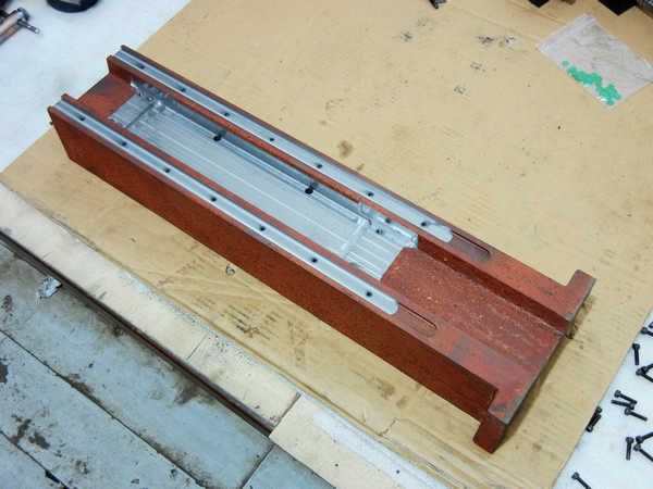
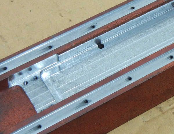
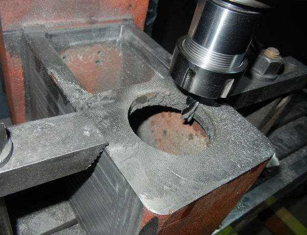
    Guys, I just finished one part machining these 4 days I think for CNY time. It's the column part I just finished milling and tapping. This a part I'm most satisfied until now

    I had to mill the bottom of the big slot because the rough machining done before didn't leave enough depth. This costed me some more time, but make the colum also more "shining".

    I will mill the last big part--spindle box next. then almost the hard work part will be finished and I can start the assembling works then.


    www.skyfirecnc.com
    Email: info@skyfirecnc.com; Skype: skyfirecnc


  10. #110
    Registered
    Join Date
    Jan 2008
    Location
    USA
    Posts
    52
    Downloads
    0
    Uploads
    0

    Default

    Quote Originally Posted by lakeside53 View Post
    Actually... today they (the type I'm taking about) are both permanent magnet As the cost of the AC servo amp falls (high only because of limited numer of manfs and industrial orientation), they will beome the common standard (if the rare earth supply isn't contrained by politics and profit motives!).

    I'm surprised that you find milling loads to be "peaky" and can design the machine to work in that range. Sure, I can see that with small or intermittent cuts, but continuous tool paths provide constant load to the spindle. I watch the spindle current on my cnc BP and it is very constant when hogging out, with some operations taking 5-10 minutes between pauses. I can even see the effects of tool wear (spindle load rises for the same speed/feed) and get a good indicator when to change. By using "peak" as a design criteria, won't you have to rate your machine differently for different operations? Does you servo amp keep track of the peak and duty cycle useage (mine does), and fault or error /warn on overuse?

    And for some reason I though you were building a lathe. Oh well... it's all good stuff.

    For completeness and other readers, here's the same calculators for milling :

    Milling Speed and Feed Calculator
    Milling Horsepower Calculator


  11. #111
    Registered Skyfire's Avatar
    Join Date
    Jul 2011
    Location
    Afghanistan
    Posts
    441
    Downloads
    0
    Uploads
    0

    Default

    Thanks to Lakeside53. Really very good calculating tools for cutting works. I stored both of lathe and mill.

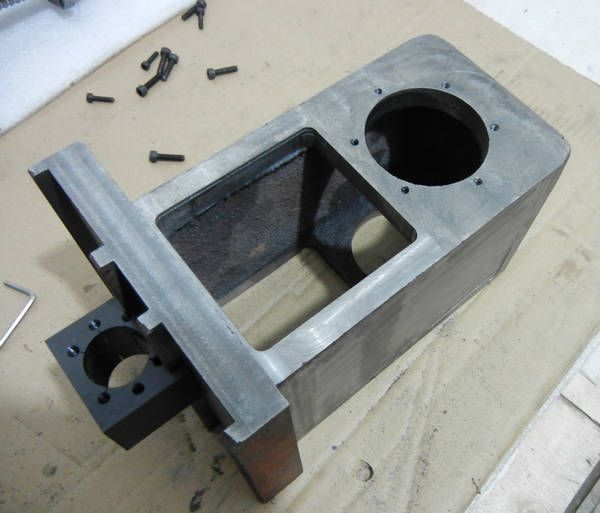
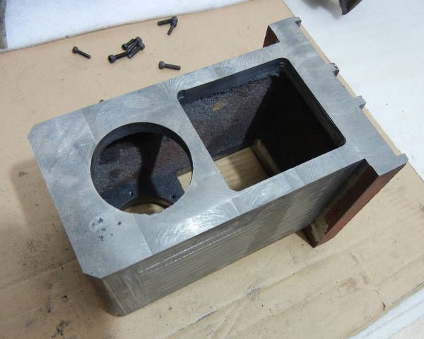
    I finished the most part of the millings of the spindle box. This is really some complex part to deal with. I must make sure several mounting surfaces exactlly perpendicular so the head will not lean and make sure the spindle and motor will also just vertical to worktable. I tried some methods to make this real. Of course I don't need to worry about this issue when some real production bacause it's real machining man's concern. But I must do this on myself for this first one.

    Any way I think I did it. Get very tired now so I just took several pictures. A little more cuttings will be done tomorrow to make all surfaces just smooth and regular, but no precision works needed any more. The spindle holes on top and bottom cost me some long time for tool setting to make sure the two holes are of best alignment. I don't need to worry about this next because the boring mill in formal machining will finish both of them one time together. This part must be controlled by MACH3 also. seems worked well.

    I think next works will be some smooth and fast until all main parts assembled and start putty and painting works. I will get such works done ASAP and start some electric works and tests.


    www.skyfirecnc.com
    Email: info@skyfirecnc.com; Skype: skyfirecnc


  12. #112
    Member handlewanker's Avatar
    Join Date
    Sep 2006
    Location
    Australia
    Posts
    6463
    Downloads
    0
    Uploads
    0

    Default

    Hi skyfire, just as observation.....the biggest problem of any verticle mill is the weight of the Z axis and having all that casting in the box to carry not only the spindle but the drive motor too.

    I would have to think that the actual spindle and work holding mechanism would only occupy approx 1/10th of the total weight of the Z head casting.

    If this is intended to be a commercial break through and go beyond where other bench mills have gone for CNC useage but as a CNC mill from the beginning instead of as a retrofit, then I would have thought that the casting and box could be eliminated completely if the spindle and motor were incorporated as one unit....already available I know, but for this project it would put it into the 21st centurty thinking completely, instead of partly in the 20th with the Z axis still having a large body of excess metal to move about.

    This is how I would have designed the "New Wave" CNC table top mill, which so far has only been available by retrofitting existing manual mills, having a quill that is not used for Z axis movements.

    I see on Ebay that a gantry router is available with a water cooled motor spindle of about 1.5 HP, and this motorised spindle is available as a replacement retrofit for existing package supplied ganty routers.

    Apart from low speed and torque required for tapping and/or reaming operations, what is the necessity for any low speed preference that makes the low speed torque necessary so requiring to have a two stage belt drive to achieve this?

    The largest diam cutter would be for ER25 approx 15mm, making no use of low speed ever, especiall if carbide cutters were in normal useage.

    Given the choice I would not go for the head casting design, but lean heavily, with the money aspect as a factor, to the water cooled motorised spindle.

    If the tapping operation is a big desire, then I would have to counter argue against this by stating that in most, if not the majority of work, tapping occupies a very few of the operations performed, and so can be done as a second operation off the machine by a dedicated simple drill set-up with tapping head, so making the CNC mill far more efficient.

    As for reaming, well the reaming operation does not absorb much torque and so can be performed with the motor spindle running at low speed for a short time without overheating.....it's water cooled anyway.

    large diam holes are not a problem as the boring head has become obsolete now that CNC can do any boring that is required, and boring heads could never be used under CNC conditions without being reset by hand at every diam increase.

    I may have missed the real need for a slow hi torque spindle speed on a table top mill, if so, enlighten me as I am having this as a preference not to have in any mill I will build.

    BTW, you are quite right, a .75hp 3,000 rpm AC motor does weigh quite a bit, even when it's 3 phase.
    Ian.


  13. #113
    Member handlewanker's Avatar
    Join Date
    Sep 2006
    Location
    Australia
    Posts
    6463
    Downloads
    0
    Uploads
    0

    Default

    Hi again, BTW, looking at the photos in post #111, the 2nd and 3rd ones, it would be very easy to "modify" the head casting by CUTTING OFF the casting body casing flush with the face and so enabling a water cooled spindle to be fitted....a perfect retrofit without the weight, just needs the motor spindle mounting bracket.
    Ian.


  14. #114
    Registered Skyfire's Avatar
    Join Date
    Jul 2011
    Location
    Afghanistan
    Posts
    441
    Downloads
    0
    Uploads
    0

    Default

    Quote Originally Posted by handlewanker View Post
    Hi skyfire, just as observation.....the biggest problem of any verticle mill is the weight of the Z axis and having all that casting in the box to carry not only the spindle but the drive motor too.

    I would have to think that the actual spindle and work holding mechanism would only occupy approx 1/10th of the total weight of the Z head casting.

    If this is intended to be a commercial break through and go beyond where other bench mills have gone for CNC useage but as a CNC mill from the beginning instead of as a retrofit, then I would have thought that the casting and box could be eliminated completely if the spindle and motor were incorporated as one unit....already available I know, but for this project it would put it into the 21st centurty thinking completely, instead of partly in the 20th with the Z axis still having a large body of excess metal to move about.

    This is how I would have designed the "New Wave" CNC table top mill, which so far has only been available by retrofitting existing manual mills, having a quill that is not used for Z axis movements.

    I see on Ebay that a gantry router is available with a water cooled motor spindle of about 1.5 HP, and this motorised spindle is available as a replacement retrofit for existing package supplied ganty routers.

    Apart from low speed and torque required for tapping and/or reaming operations, what is the necessity for any low speed preference that makes the low speed torque necessary so requiring to have a two stage belt drive to achieve this?

    The largest diam cutter would be for ER25 approx 15mm, making no use of low speed ever, especiall if carbide cutters were in normal useage.

    Given the choice I would not go for the head casting design, but lean heavily, with the money aspect as a factor, to the water cooled motorised spindle.

    If the tapping operation is a big desire, then I would have to counter argue against this by stating that in most, if not the majority of work, tapping occupies a very few of the operations performed, and so can be done as a second operation off the machine by a dedicated simple drill set-up with tapping head, so making the CNC mill far more efficient.

    As for reaming, well the reaming operation does not absorb much torque and so can be performed with the motor spindle running at low speed for a short time without overheating.....it's water cooled anyway.

    large diam holes are not a problem as the boring head has become obsolete now that CNC can do any boring that is required, and boring heads could never be used under CNC conditions without being reset by hand at every diam increase.

    I may have missed the real need for a slow hi torque spindle speed on a table top mill, if so, enlighten me as I am having this as a preference not to have in any mill I will build.

    BTW, you are quite right, a .75hp 3,000 rpm AC motor does weigh quite a bit, even when it's 3 phase.
    Ian.
    Hi, thank you for your great ideas. I'm sure your are very experienced in this field and actually we have many same concerns here on the spindle issue.

    I agree that the head weight issue is critical for every CNC. I have tried to make the spindle box as light as possible but ensure quite good rigidity as the basic thinking. Totally I made the spindle box <10kg and totally the head will be about 15kg after spindle and motor installed. I think it's some balanced result now. I don't want to make the head too light because rigidity is still my concern and this will make sure the head be stable under any cutting conditions. And I will add a spring to banlance the head weight. It doesn't solve all of the Z rapid move problem but will be much better. And Z drive motor will be enough torque. I know the shortcomings of the stepper motors and will use some high drive voltage to make sure the Z drive will not lose steps.

    And abou the whole machine, basically I take it as a mill can do everything may need on it. So I considered much about the low speed applications, high speed applications, taping etc. I agree with your thinkings that most of the CNC work need high speed milling and sometimes carving works are much more important than the works within low speed range. So My last decision will be two options.

    1. Just make some banlance on "only machinery spindle". I will give two pulley avaliable for speed range "200-3000(or 4500)" and "400-6000(or 9000)". This can be some easy way to change the pulley. I will see just the machinery spindle can handle how high speed. The lower range will be big torque for some hard works, and the high speed range will be ok for most milling and carving works. I think it's some reasonable solution here.

    2. From the initial thinking and design, I have made the motorised spindle as the standard configuration. But now I make it as another optional choice together with typical machinery spindle system. I designed the spindle box can compatible for both of them. exchangable. So everyone can just select what they need or take both of them and exchange under different applications. I have seleced some standard 1.5kw motorised spindles for this options too.

    So I think this is some best solution to cover every possible customer's needs.

    And, I have another concern of the cost issue too. You know, there are many water coolling motorised spindles on market now, not expensive, and fitful to many carving cuttings. My really concern is that, most of the motorised spindles are designed to cut soft materiales, aluminium at most. The reason is the bearing system inside are some weak for hard working like steel cutting. And we do have options of rigid motorised spindles to handle the steel cuttings. But the price is about 3-4X. So this will make the cost rise much. So this maybe not acceptable to some customers. If I just use some common motorised spidles and say this is no problem. I must will screw up because the bearings inside will be dead after several monthes I guess.

    So, based on all of above, I will make a rigid machinery spindle system; and I will make optional motorised spindle system, just leave people to choose. I will also install the water cool motorised spindle system for demo when machine structure finished.

    And, Yes. I really had thought cut off the front face of the spindle box to fit the motorised spindle but I'm thinking to make some mounting parts to solve this now for compatible choises and machine looks nice of course...haha

    very appreciate for your great inputs. I hope to talk more next.

    www.skyfirecnc.com
    Email: info@skyfirecnc.com; Skype: skyfirecnc


  15. #115
    Registered Skyfire's Avatar
    Join Date
    Jul 2011
    Location
    Afghanistan
    Posts
    441
    Downloads
    0
    Uploads
    0

    Default

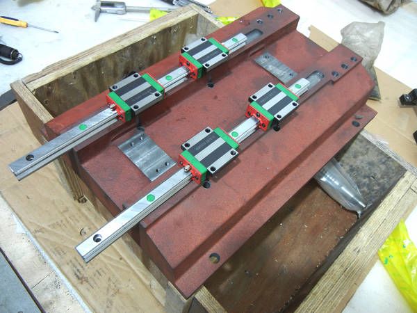
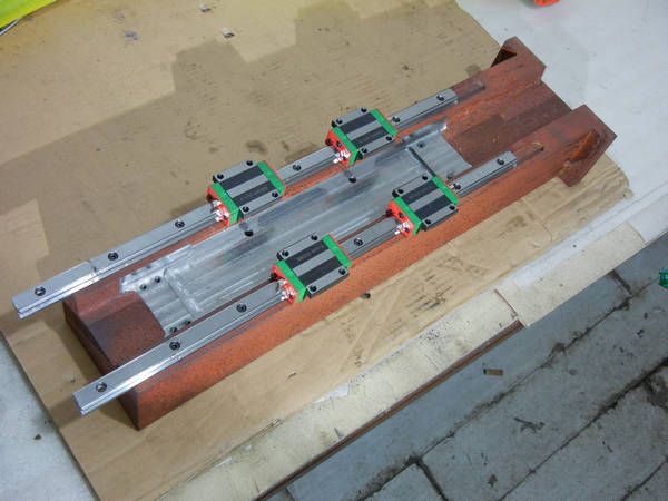
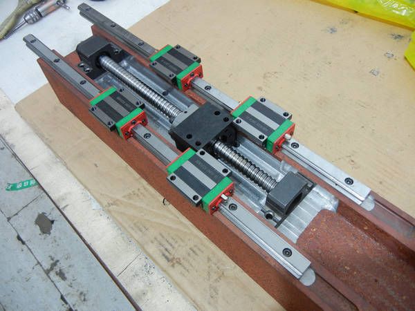
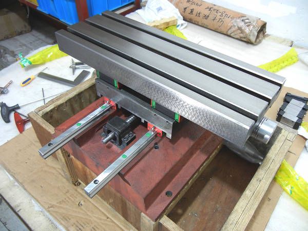
    Hi guys. I've started the formal assembling of the machine. It's quite smooth until now. The worktable has been ground urgently and the saddle sides just finishing milled to be more shining.

    First works are just the same linear installation and adjustment as I did on worktable part. At last I also got about 0.01mm parellel error.


    Fit the worktable and saddle parts on the base: half done by now.


    www.skyfirecnc.com
    Email: info@skyfirecnc.com; Skype: skyfirecnc


  16. #116
    Registered Skyfire's Avatar
    Join Date
    Jul 2011
    Location
    Afghanistan
    Posts
    441
    Downloads
    0
    Uploads
    0

    Default

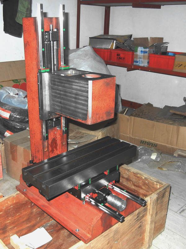
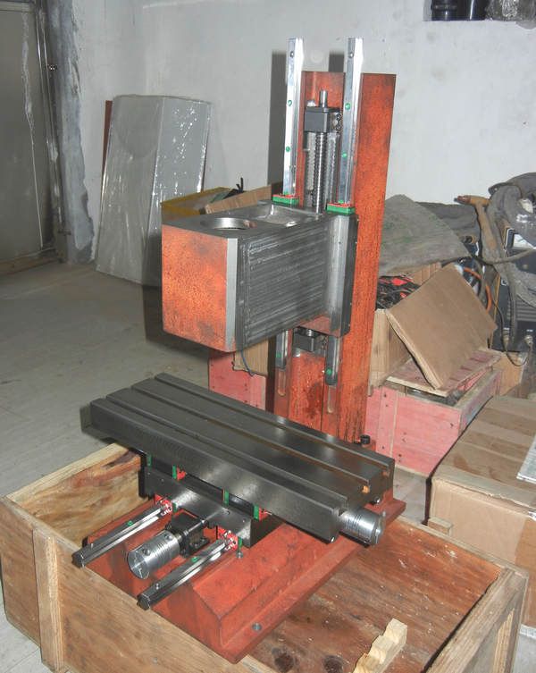
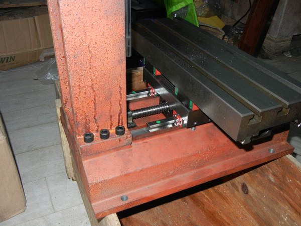
    I've finished the machine body assembling now. Not much story this part, Mostly are screw works. All parts fit well and run smooth. Next I will install the motors and adjust the accuracy next. That will be some skillful and careful works then.

    The machine is nearly formed now:


    I set 6 big bolts for the column so should be very strong for such a benchtop size machine.


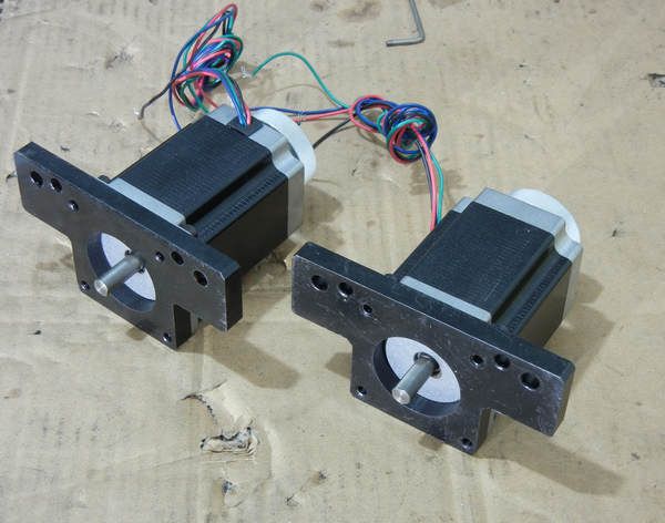
    The stepper motors and brackets. I will install them tomorrow. The brackets had been wire cutted long time ago.


    www.skyfirecnc.com
    Email: info@skyfirecnc.com; Skype: skyfirecnc


  17. #117
    Registered johnohara's Avatar
    Join Date
    Aug 2008
    Location
    www.johnohara.net
    Posts
    247
    Downloads
    0
    Uploads
    0

    Default

    Skyfire~

    I enjoy reading this thread. Thank you for sharing your work.

    ~john


  18. #118
    Gold Member LeeWay's Avatar
    Join Date
    Jun 2004
    Location
    United States
    Posts
    6618
    Downloads
    2
    Uploads
    0

    Default

    Looking very cool.
    It looks pretty sleek.
    What color or colors have you chosen to do it in?

    Not that it makes a lot of difference. It will look sharp in any color and work the same as well.

    Lee


  19. #119
    Registered Skyfire's Avatar
    Join Date
    Jul 2011
    Location
    Afghanistan
    Posts
    441
    Downloads
    0
    Uploads
    0

    Default

    Quote Originally Posted by johnohara View Post
    Skyfire~

    I enjoy reading this thread. Thank you for sharing your work.

    ~john
    Hi johnohara, thanks for reading my thread. Welcome any comments here!~

    www.skyfirecnc.com
    Email: info@skyfirecnc.com; Skype: skyfirecnc


  20. #120
    Gold Member LeeWay's Avatar
    Join Date
    Jun 2004
    Location
    United States
    Posts
    6618
    Downloads
    2
    Uploads
    0

    Default

    Come to think of it, it doesn't look too bad in iron oxide.

    For what it is worth, I did my mill in gloss black. It looked very nice to start with, but just like on a car, it shows everything. Chips stand out like diamonds. Sparkles and glitters and lets me know I haven't been doing very good housekeeping.

    Lee


Page 6 of 183 FirstFirst ... 34567891656106 ... LastLast

Tags for this Thread

Posting Permissions

  • You may not post new threads
  • You may not post replies
  • You may not post attachments
  • You may not edit your posts
  •  


About CNCzone.com

    We are the largest and most active discussion forum for manufacturing industry. The site is 100% free to join and use, so join today!

Follow us on


Our Brands

Show how to build a CNC machine from the very beginning to the end

Show how to build a CNC machine from the very beginning to the end