Reply with Quote
The long awaited all-axes jog test. Finally!
About 75 IPM for X rapids. Not bad for the 17 TPI stock screw.
CR.


Here's the whole shebang, wired and almost ready-to-go:
The temporary twist ties holding the X motor cable will be replaced with stronger wire-ties when finished.
CR.
Last edited by Crevice Reamer; 09-04-2010 at 02:43 PM.
http://crevicereamer.com
Too many PMs. Email me to my name plus At A O L dot com.
The long awaited all-axes jog test. Finally!
About 75 IPM for X rapids. Not bad for the 17 TPI stock screw.
CR.
Last edited by Crevice Reamer; 09-05-2010 at 12:57 PM.
http://crevicereamer.com
Too many PMs. Email me to my name plus At A O L dot com.
You did well with you choice of G540/ motors and PSU. Very well matched set. This thing is going to really fly once you use ballscrews.
Last edited by RotarySMP; 09-05-2010 at 02:43 PM.
Regards,
Mark
Thanks Mark!
I agree, and it should be pretty fast with the Acme also.
CR.
http://crevicereamer.com
Too many PMs. Email me to my name plus At A O L dot com.
New pics have been added to above post# 159.
Let's make sure the home switches work with Mach3. I haven't installed the Z vane yet, so will simulate that with a strip of metal passed through the Z switch slot. The X switch can be activated by simply pressing the button:
TEST SUCCESSFUL!
The blinking LEDs indicate that both Hall-Effect switches are being seen by Mach3.
CR.
http://crevicereamer.com
Too many PMs. Email me to my name plus At A O L dot com.
Let's make and install the vane for Z axis Hall Effect switch. This would come out much neater if cut by CNC:
Ajustment slot cut by hand with a cutting disk and smoothed with file:
Bending:
Final shape:
Mounting layout:
Vane mounted:
The upper shield protects the vane tab from swarf:
Z Axis homed:
X Axis homed:
CR.
Last edited by Crevice Reamer; 09-07-2010 at 09:18 AM.
http://crevicereamer.com
Too many PMs. Email me to my name plus At A O L dot com.
Auto zero is turned OFF:
CR.
http://crevicereamer.com
Too many PMs. Email me to my name plus At A O L dot com.
X axis backlash test:
X axis has ZERO backlash!!!
Z axis backlash test:
Z axis has 0.0076 backlash.
CR.
http://crevicereamer.com
Too many PMs. Email me to my name plus At A O L dot com.
Let's make a belt cover from galvanized sheet metal:
First cut the basic shape, file the edges smooth and drill mounting holes:
You don't HAVE to have a sheet metal brake. Use welding pliers and make the bends a little at a time:
Mounted cover:
CR.
http://crevicereamer.com
Too many PMs. Email me to my name plus At A O L dot com.
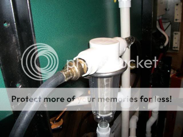
Here are the pressure-side flood cooling parts:
The pump/pressure relief valve is connected to a washing-machine hose, which is connected to a flushable spin-sediment filter for fines, which is connected to two short air hoses, which are connected to the grizzly magnetic-base nozzle manifold.
CR.
http://crevicereamer.com
Too many PMs. Email me to my name plus At A O L dot com.
Let's add an overflow to the coolant basin:
First a hole is drilled:
Then a rubber gasket is fabricated:
And the fitting is installed:
Finally the hose is attached:
Hopefully, I will find the clamps bought for this, before coolant has to flow.
CR.
http://crevicereamer.com
Too many PMs. Email me to my name plus At A O L dot com.
Lets mount the fines filter with this large muffler clamp. It is a hair smaller than filter diameter:
Holes are marked on backsplash:
And drilled:
Clamp will mount like this:
After a little filing of plastic, filter mounted:
CR.
http://crevicereamer.com
Too many PMs. Email me to my name plus At A O L dot com.
Man I bet your digital camera is tired
nice, ive been waiting for the coolant part of this project. you are making great progress!
Inlet hose to filter:
Outlet hose from filter:
Hose snakes under lathe, and allows for coolant drip-off:
Final delivery and control manifold:
CR.
http://crevicereamer.com
Too many PMs. Email me to my name plus At A O L dot com.
what type of coolant do you plan to use?
Last edited by will gilmore; 09-16-2010 at 12:25 PM. Reason: spelling
Synkool.Originally Posted by will gilmore

CR.
http://crevicereamer.com
Too many PMs. Email me to my name plus At A O L dot com.
I like you attention to detail. It's the small things that make an entire job that much easier.
~Scott
Thanks Scott.
CR.
http://crevicereamer.com
Too many PMs. Email me to my name plus At A O L dot com.
Looks GREAT! I've had my G0602 on cnc for almost 2 years now, it's a wonderful machine. I'm using 5/8" ballscrews and roton nuts and I get 100ipm on the Z and 140ish on the X, that's at 50v. Any faster and it can stall doing some hard operations. I mounted the X ballscrew directly underneath the cross slide and bolted the roton underneath in the front by milling out a pocket and drilling two holes.
I've got 425oz motors on both and I still stall the Z sometimes when drilling, if the bit is dull or I get the speed/feed wrong. Otherwise it's a brute. I am quickly growing out of the 1hp spindle though, at 2400rpm where I usually run it for AL I can get it to stall. (though that's taking a 0.375" dia DOC when boring at 0.75ipm with coolant, asking a bit much? haha). 2-3hp with VFD would be my next step, do you know if I can still run something like that on 110v?
You're going to want a splash shield above the lathe otherwise coolant will fling EVERYWHERE. I made mine on a hinge with a spring, it covers the top and front, letting the coolant drip down the front or down the stock splashpan, and it goes about halfway down the bed which is enough. I'd like to build a table like yours with a full enclosure and a much deeper chip tray.
I set up X and Z limits but never use them. Z limit is almost pointless because different tools are closer or farther from danger so you'd have to change it with every tool change, so I unplugged mine and just "try" to code wisely. X limit also never touches, but my microswitch is in a perfect place where I rest my hands, so I use it as an estop while I'm watching the machine work.
Last year I bought a used Valenite centerdex boring bar on ebay for ~$60, what an incredible investment! I have to do a lot of boring in aluminum, like 2" dia holes 1" deep, this tool is amazing. 1" dia, 3/4" shank, no centerdrilling or predrilling required, just plow it in. Next to the centerdex my other favorite tool is a 35° right turning tool. And if you cut a lot of aluminum then definitely get some "for aluminum" inserts like the ones that I use from KBCtools.com (pg 251), good price and they leave a glass smooth surface finish which completely pwns other inserts.
I never really get a chance to talk about my cnc tools so sorry if I'm gushing, haven't had time to set up a build thread or anything. Ohh I did figure out a way to wire the spindle contactor so that Mach3 can rotate it clockwise or counterclockwise using two outputs, that took a good day of fooling around to understand. It's great because it lets me do my boring with M3, stop the spindle, turn it backwards with M4 and do OD machining on the back of the part using X-3.00 type numbers. That gets one entire side of an part done with one tool. Fun stuff.
My backlash with the ballscrews is under 0.002 for both, and that's with stock balls. I think even just 0.125" balls would make it a bit tighter without going too tight, maybe one day.
Great build and keep having fun with it, can't wait to see some completed parts!
John