Build Thread G0602 10x22 LATHE 3 STEP CNC CONVERSION - Page 4


Page 4 of 11 FirstFirst 1234567 ... LastLast
Results 61 to 80 of 216

Thread: G0602 10x22 LATHE 3 STEP CNC CONVERSION

  1. #61
    Registered Crevice Reamer's Avatar
    Join Date
    Mar 2008
    Location
    USA
    Posts
    3655
    Downloads
    0
    Uploads
    0

    Default SWING-ARM AND SENSOR INSTALLATION

    Here is the finished swing-arm, with HE sensor attached:


    I used 6-32 x 1/2 flat head screws because that's what was on hand. They will be replaced with brass or aluminum machine screws, (non magnetic) and Loctite.


    Swing-arm & sensor installed onto lathe:


    Sensor/vane alignment:


    The wiring will be fed thru a hole in the headstock.

    CR.

    http://crevicereamer.com
    Too many PMs. Email me to my name plus At A O L dot com.


  2. #62
    Registered Crevice Reamer's Avatar
    Join Date
    Mar 2008
    Location
    USA
    Posts
    3655
    Downloads
    0
    Uploads
    0

    Default

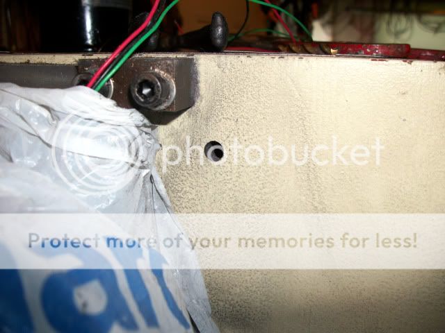
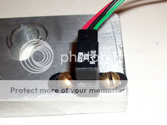
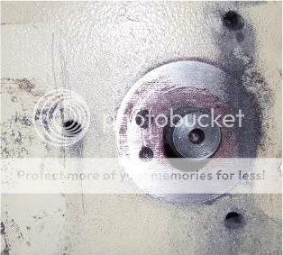
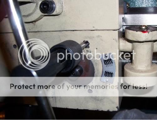
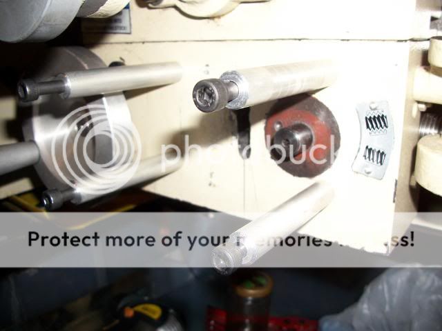
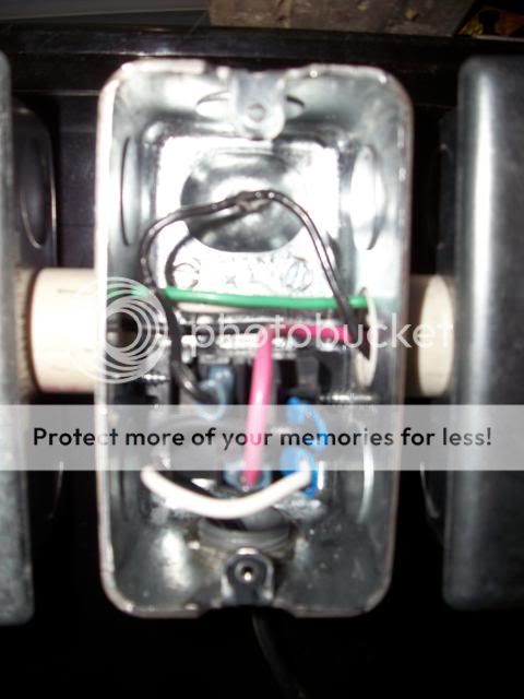
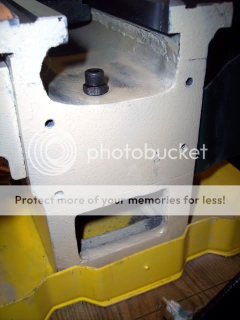
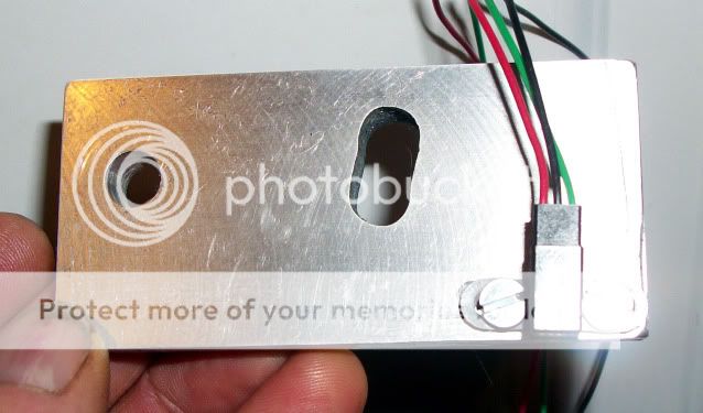
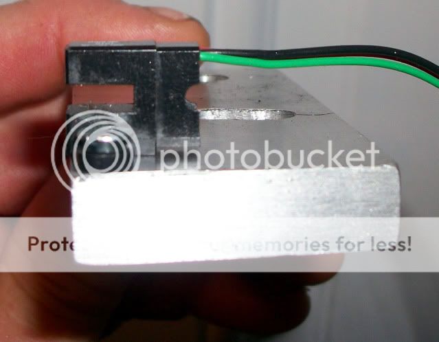
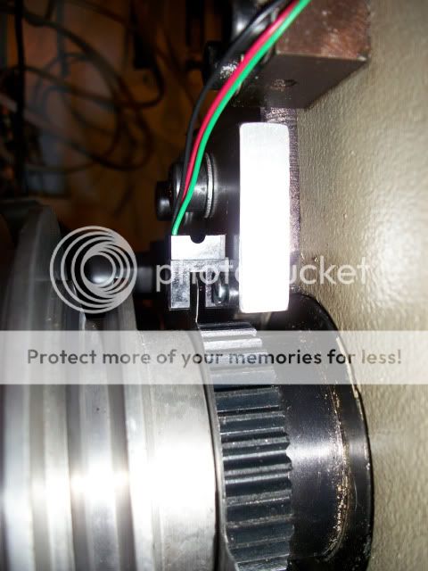
    Hole for wiring drilled. Plastic is to keep cast iron dust away from sensor:


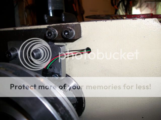
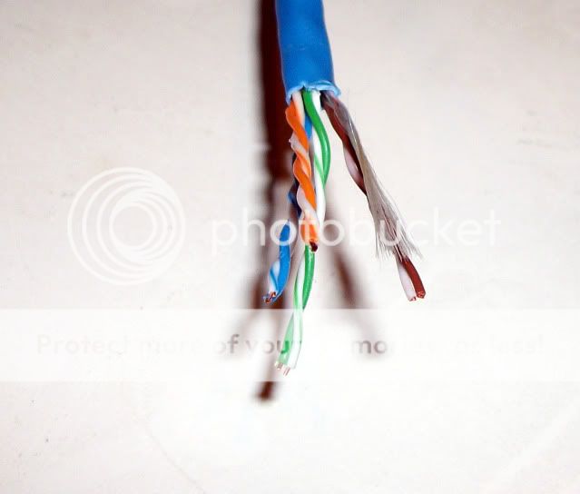
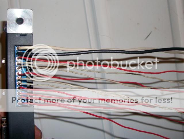
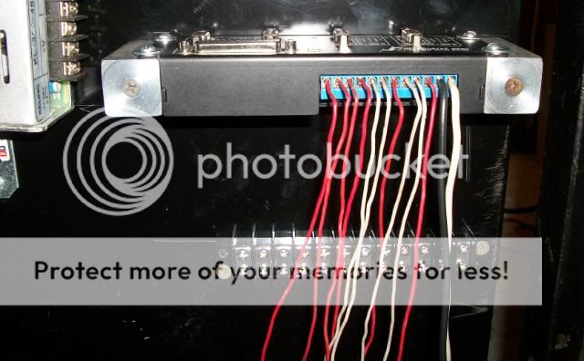
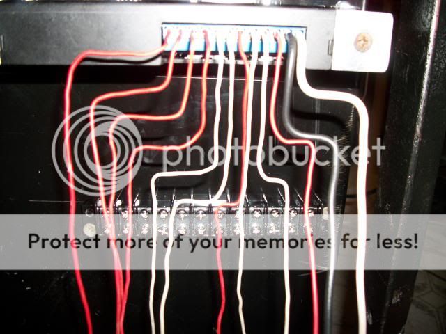
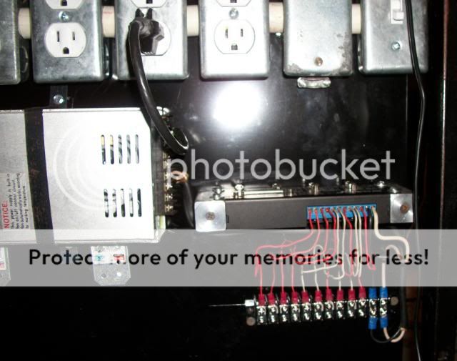
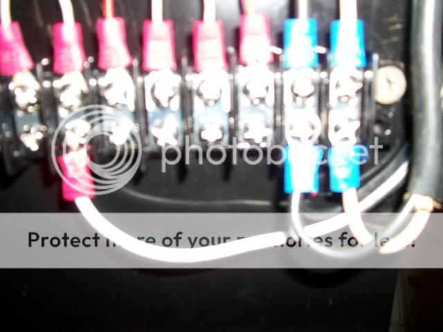
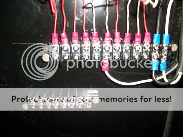
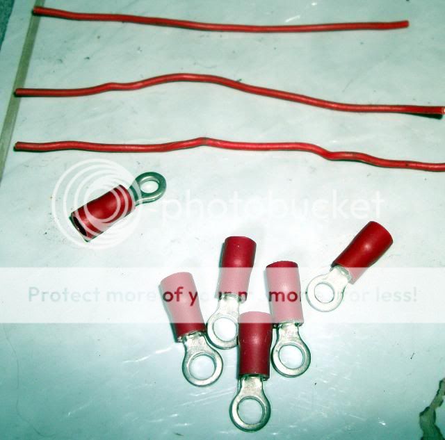
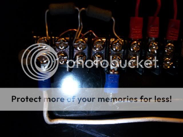
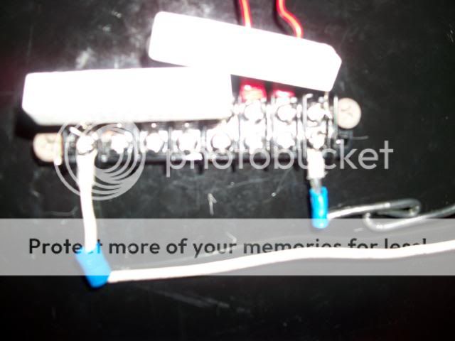
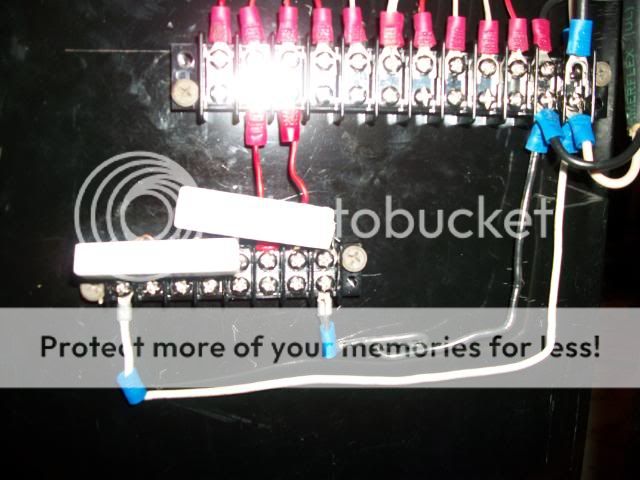
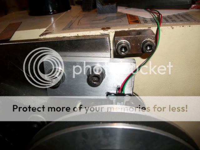
    The wires will eventually be heat-shrinked and lead to this electrical box:


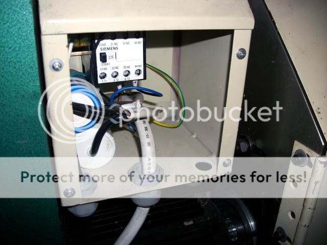
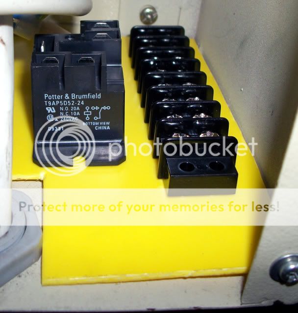
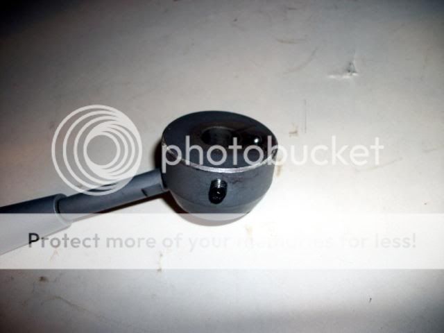
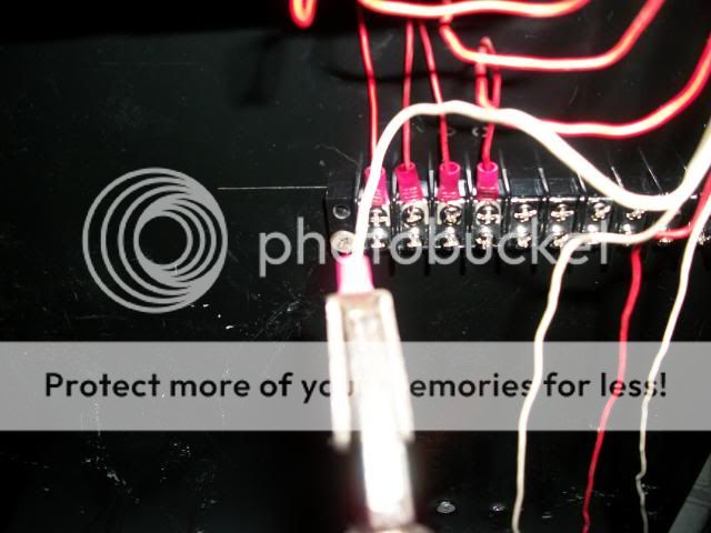
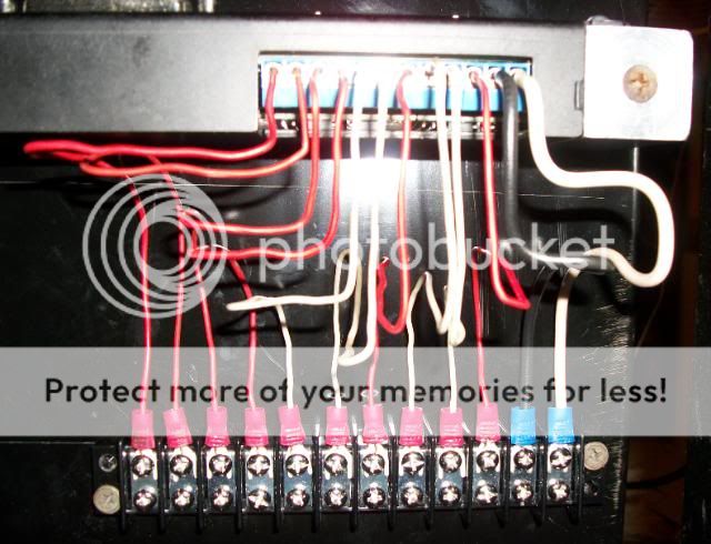
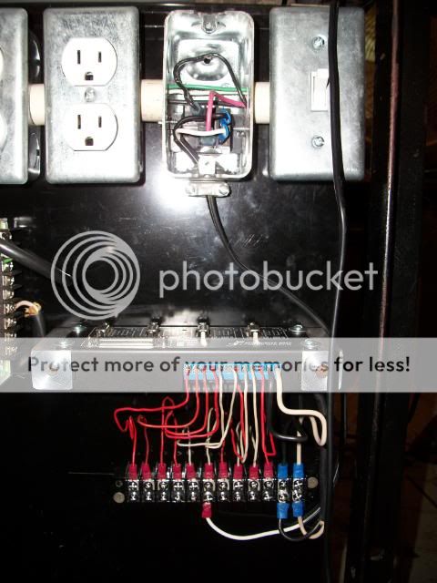
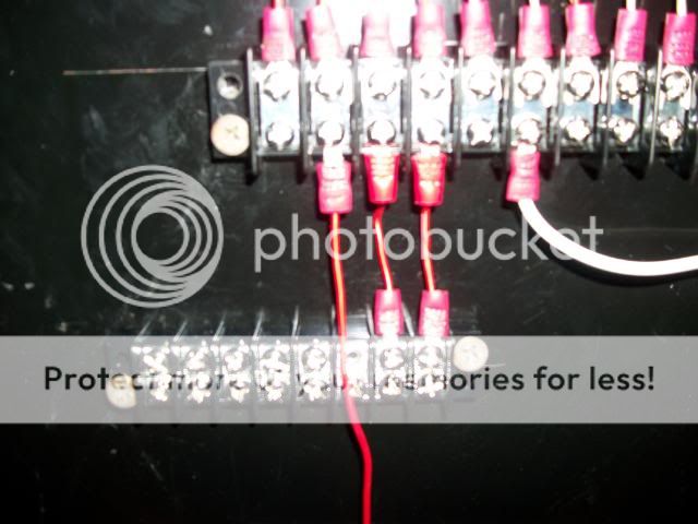
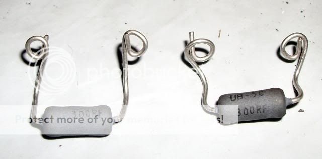
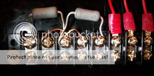
    Where the motor control relay, terminal strip and 24V Voltage divider will reside:


    By using a SPDT relay, manual control of motor is retained.

    CR.

    http://crevicereamer.com
    Too many PMs. Email me to my name plus At A O L dot com.


  3. #63
    Registered Crevice Reamer's Avatar
    Join Date
    Mar 2008
    Location
    USA
    Posts
    3655
    Downloads
    0
    Uploads
    0

    Default

    Got the brass non-magnetic screws for the threading sensor:


    And this 24 gauge CAT-5 quad twisted pair wire for wiring up the electrical box:


    This was supposed to have been SHIELDED/stranded wire, but apparently the salesman lied. The cable must carry +/- 48V, plus a relay output, plus the sensor input, plus the Estop wire. The solid wire is probably OK, since there will be no flexing. Only time will tell if the lack of shielding will cause problems.

    CR.

    http://crevicereamer.com
    Too many PMs. Email me to my name plus At A O L dot com.


  4. #64
    Registered Crevice Reamer's Avatar
    Join Date
    Mar 2008
    Location
    USA
    Posts
    3655
    Downloads
    0
    Uploads
    0

    Default

    The non-shielded cable is causing a wiring change. I WAS going to run 48V to the box and then Voltage divide that down to 24V. The Sensor wire leading down to G540 is the only PULSING wire. In order to cancel out that pulse, I will Keep the 24V divider close to G540 and run 2 separate 24V wires to the electrical box: One for the relay and the other paired with the sensor input. Hopefully, this opposite flowing electricity within the twisted pair will cancel the pulsing magnetic field, and eliminate any crosstalk.

    CR.

    http://crevicereamer.com
    Too many PMs. Email me to my name plus At A O L dot com.


  5. #65
    Registered Crevice Reamer's Avatar
    Join Date
    Mar 2008
    Location
    USA
    Posts
    3655
    Downloads
    0
    Uploads
    0

    Default

    Sorry! I have not been able to update this build for awhile. For some reason Photobucket won't upload my pics. It keeps giving this message:

    Image upload failed
    Upload failed for 101_0047_edited.JPG with error: File not uploaded

    Anybody know how to fix this?

    CR.

    http://crevicereamer.com
    Too many PMs. Email me to my name plus At A O L dot com.


  6. #66
    Registered
    Join Date
    Mar 2010
    Location
    USA
    Posts
    816
    Downloads
    0
    Uploads
    0

    Default

    Quote Originally Posted by Crevice Reamer View Post
    Sorry! I have not been able to update this build for awhile. For some reason Photobucket won't upload my pics. It keeps giving this message:

    Image upload failed
    Upload failed for 101_0047_edited.JPG with error: File not uploaded

    Anybody know how to fix this?

    CR.
    How much free space does Photobucket say you have left. Only other time I got that message was when the file was too big for photobucket to reduce down.


  7. #67
    Registered Crevice Reamer's Avatar
    Join Date
    Mar 2008
    Location
    USA
    Posts
    3655
    Downloads
    0
    Uploads
    0

    Default

    Thanks Magnum! Photobucket is at 25% capacity. My old 6 MP camera died. The new larger one may well be producing pics that are too large. Photoshop SE 3.0 doesn't seem to accept them either. Managed to get a few pics uploaded though:

    Time to consider the X motor mounting:


    This handle must be removed. There is a set screw underneath, and a ball bearing inside. First, set the half nut friction to optimum:


    There is not enough room behind the X shaft for the full length of the motor:


    I must either cut off the rear shaft, or cut a slot into the apron. If I was going to cut off the shaft, I would first drill and place a plastic shield to keep steel dust out of the motor, then use a cutting disk. I opted though, to cut a slot into the apron.

    This label is in the way:


    CR.

    http://crevicereamer.com
    Too many PMs. Email me to my name plus At A O L dot com.


  8. #68
    Registered
    Join Date
    Mar 2010
    Location
    USA
    Posts
    816
    Downloads
    0
    Uploads
    0

    Default

    Quote Originally Posted by Crevice Reamer View Post
    Thanks Magnum! Photobucket is at 25% capacity. My old 6 MP camera died. The new larger one may well be producing pics that are too large. Photoshop SE 3.0 doesn't seem to accept them either. Managed to get a few pics uploaded though:
    Glad that was it.. Yea, I was trying to upload some 6MB pics and it croaked on me as well a while back.

    Build is looking good, very informative. You are saving me the trouble of having to tear mine down to see what makes it tick


  9. #69
    Registered Crevice Reamer's Avatar
    Join Date
    Mar 2008
    Location
    USA
    Posts
    3655
    Downloads
    0
    Uploads
    0

    Default

    Let's drill some holes and a slot. Slot starts with a center hole:


    Two more holes are added:


    Holes are blended together with round file and a slot is born:


    WARNING: THE Z LEAD SCREW IS BEHIND THESE HOLES. PUT A PIECE OF WOOD BEHIND TO PROTECT THE SCREW WHEN DRILLING.

    CR.

    Last edited by Crevice Reamer; 07-06-2010 at 09:59 AM.
    http://crevicereamer.com
    Too many PMs. Email me to my name plus At A O L dot com.


  10. #70
    Registered Crevice Reamer's Avatar
    Join Date
    Mar 2008
    Location
    USA
    Posts
    3655
    Downloads
    0
    Uploads
    0

    Default

    Now to tap some holes. The apron is fairly soft cast iron, but be careful. This is no time to break a tap:


    And then test-install some standoffs and long bolts:


    CR.

    http://crevicereamer.com
    Too many PMs. Email me to my name plus At A O L dot com.


  11. #71
    Registered Crevice Reamer's Avatar
    Join Date
    Mar 2008
    Location
    USA
    Posts
    3655
    Downloads
    0
    Uploads
    0

    Default

    Let's wire up the G540, with solid copper wire. For the power connections I'm using 14 gauge house wire:


    The wires will be "quick disconnect" connected to the 12 position terminal strip with these slide terminals:


    CR.

    Last edited by Crevice Reamer; 07-08-2010 at 09:50 AM.
    http://crevicereamer.com
    Too many PMs. Email me to my name plus At A O L dot com.


  12. #72
    Registered Crevice Reamer's Avatar
    Join Date
    Mar 2008
    Location
    USA
    Posts
    3655
    Downloads
    0
    Uploads
    0

    Default

    I use Vise Grips for crimping terminals. Once set not-too-loose and not-too-tight they crimp perfectly each time:


    CR.

    http://crevicereamer.com
    Too many PMs. Email me to my name plus At A O L dot com.


  13. #73
    Registered Crevice Reamer's Avatar
    Join Date
    Mar 2008
    Location
    USA
    Posts
    3655
    Downloads
    0
    Uploads
    0

    Default

    After you have wired the G540, check all connections with an Ohmeter.

    Now, let's wire up the Power Supply:


    Short AC line cord was cut from back of a discarded clothes dryer. Wiring to TS is type NM 14 gauge house wire. Final PSU connection to terminal strip is Quick Disconnect with slide terminals.

    CR.

    http://crevicereamer.com
    Too many PMs. Email me to my name plus At A O L dot com.


  14. #74
    Registered Crevice Reamer's Avatar
    Join Date
    Mar 2008
    Location
    USA
    Posts
    3655
    Downloads
    0
    Uploads
    0

    Default

    Let's wire up the 48V coolant-pump relay. The pump contacts take 1/4 inch spade terminals and the coil takes 1/8 inch spade terminals:


    CR.

    http://crevicereamer.com
    Too many PMs. Email me to my name plus At A O L dot com.


  15. #75
    Registered
    Join Date
    Mar 2010
    Location
    USA
    Posts
    816
    Downloads
    0
    Uploads
    0

    Default

    Speaking of Coolant. I have been looking at that on my setup. How are you planning on keeping the coolant from following the ways down thru and up under the headstock area? I can see it following that path and coming out the end of the lathe.


  16. #76
    Registered Crevice Reamer's Avatar
    Join Date
    Mar 2008
    Location
    USA
    Posts
    3655
    Downloads
    0
    Uploads
    0

    Default

    Quote Originally Posted by Magnum164 View Post
    Speaking of Coolant. I have been looking at that on my setup. How are you planning on keeping the coolant from following the ways down thru and up under the headstock area? I can see it following that path and coming out the end of the lathe.
    Hi Magnum.

    Well, remember my stand was designed from the start to incorporate flood cooling. The lathe is dead-flat level, so only drips could get that far. As a last resort, the yellow plastic catch-basins on each end should catch them:


    Flexible silicone seal around the cracks of the headstock/ways should seal out the drips though.

    There are plastic shields at each end, (here not fastened yet) to direct spray down into the main coolant basin:


    There will also be a panel, extending forward from the headstock to the above black frame-member, that should protect the controls and a spindle-bearing shield.

    CR.

    Last edited by Crevice Reamer; 07-11-2010 at 12:17 PM.
    http://crevicereamer.com
    Too many PMs. Email me to my name plus At A O L dot com.


  17. #77
    Registered Crevice Reamer's Avatar
    Join Date
    Mar 2008
    Location
    USA
    Posts
    3655
    Downloads
    0
    Uploads
    0

    Default

    Let's add an auxillery terminal strip. This strip will house the wires going to the apron area, and will be a platform for the 24V Voltage divider:


    These wirings will be semi-permanent. No need for slide terminals, so it will use terminals like this:


    Start of wiring it up:


    CR.

    http://crevicereamer.com
    Too many PMs. Email me to my name plus At A O L dot com.


  18. #78
    Registered Crevice Reamer's Avatar
    Join Date
    Mar 2008
    Location
    USA
    Posts
    3655
    Downloads
    0
    Uploads
    0

    Default

    Let's build a Voltage divider. Three 24V center terminals are joined together:


    Eyes are bent onto the 5 Watt resistors:


    Resistors mounted to terminal strip:


    Wired up with 48V:


    Now 48V is cut in half and a steady +24V is available at center terminals:


    This will power the 30V-max Hall Effect sensors and the 24V motor-control relay. There will be a constant 80mA drain on the 7.3A PSU, but There's plenty of excess Amps still available.

    CR.

    Last edited by Crevice Reamer; 07-13-2010 at 08:50 AM.
    http://crevicereamer.com
    Too many PMs. Email me to my name plus At A O L dot com.


  19. #79
    Registered Crevice Reamer's Avatar
    Join Date
    Mar 2008
    Location
    USA
    Posts
    3655
    Downloads
    0
    Uploads
    0

    Default

    Again, check all connections for continuity.

    I have misunderestimated the Wattage needed for the Voltage divider resistors. During testing, the resistors reach a temperature of 85 Centigrade or 185 Fahrenheit. This is actually workable as the T strip is good up to 120C, But I don't really want that much heat. I will replace the 5 Watt resistors with 10W. That should halve the operating temp.

    CR.

    http://crevicereamer.com
    Too many PMs. Email me to my name plus At A O L dot com.


  20. #80
    Registered Crevice Reamer's Avatar
    Join Date
    Mar 2008
    Location
    USA
    Posts
    3655
    Downloads
    0
    Uploads
    0

    Default

    The ten Watt resistors are much bigger. (Should have stayed with wire-wound) Had to change wiring layout for them. Removed an unused input wire and added a ground.

    There are now three 24V terminals and 2 Negative terminals:


    The new resistors DO run somewhat cooler, and temp is down to 150F. The 5 Watt leads were untouchably hot, but the 10W LEADS are only warm to the touch. This is acceptable and will have to serve.

    CR.

    Last edited by Crevice Reamer; 07-15-2010 at 09:35 AM.
    http://crevicereamer.com
    Too many PMs. Email me to my name plus At A O L dot com.


Page 4 of 11 FirstFirst 1234567 ... LastLast

Tags for this Thread

Posting Permissions

  • You may not post new threads
  • You may not post replies
  • You may not post attachments
  • You may not edit your posts
  •  


About CNCzone.com

    We are the largest and most active discussion forum for manufacturing industry. The site is 100% free to join and use, so join today!

Follow us on


Our Brands

G0602 10x22 LATHE 3 STEP CNC CONVERSION

G0602 10x22 LATHE 3 STEP CNC CONVERSION