6 axis control board smoked out a transistor , would need help to understand the prob


Page 1 of 2 12 LastLast
Results 1 to 20 of 32

Thread: 6 axis control board smoked out a transistor , would need help to understand the prob

  1. #1
    Member
    Join Date
    Jan 2018
    Location
    Canada
    Posts
    106
    Downloads
    0
    Uploads
    0

    Default 6 axis control board smoked out a transistor , would need help to understand the prob

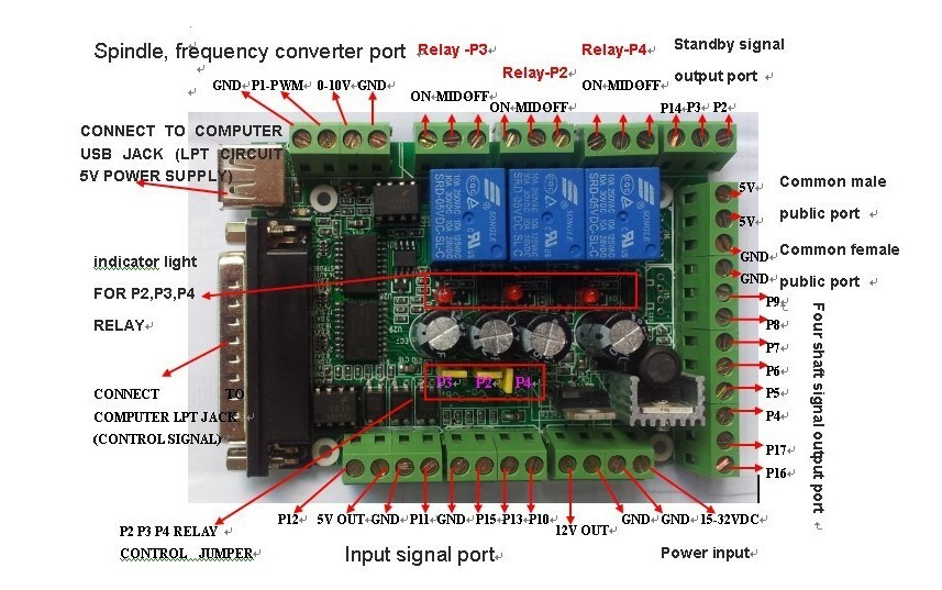
    Hello guys , i was setting up the Spindle/VFD section of my cnc router table controller https://www.automationtechnologiesin...face-breakout/ and one of the transistor smoked out ....

    i am trying to find the real reason why it smoked out before ordering a new one , waiting for delivery , reconnecting and burning a second board....

    It ran well for every axis steppers , i made the machine move around no problems , i used the VFD control screen , started , stop , rpm control potentiometer everything was fine . I needed to hook up to the Spindle RPM controller section and understand how to set it up and it burned a transistor .... it hurts !

    this transistor with the heatsink burnt


    i was really following this pinout plan


    Things i did since the last run

    - the twisted wires are there to control solenoid air valves who were not set yet , just hooked them up , 2 common grounds and 2 output pins

    - i hooked the VFD 10V output pin "VS" and GND to the 0-10V and GND pins of the Spindle section of the BoB , ive read a lot of things on the web and understood it would have been a isolated power supply for the BoB circuit but i think it would be an error i did ....

    - i hooked the BoB P1-PWM pin to the "AI" VFD
    - on the BoB i used one relay to bridge the VFD common ground to his "X1" pin to turn it ON/OFF thru Mach3 and selected the F1.08 on the VFD screen and didnt try it yet , it started smell burnt 2-3 minutes after the system got powered up ... i was still into Mach3 config

    i am wondering if the grounds pins GND on the BoB and "CM" and "GND" on the VFD were actually hooked up together and was bad but i doubt.

    i ran to the machine and cut the power because smoking

    disconnected the things i just connected to the BoB

    tried to power up the system a few minutes after and it got up to smokey smokey and i see the transistor body is cracked ... really trying to understand what is the reason it smoked and wondering the transistor is on which circuit of the BoB , havent found the full board diagram of the BoB ... removed it from the mounting plate, inspected the underside and nothing looked burnt/scarred


    Some more images of the build


    I have been working on that machine since january , i am really angry of this and hurts !!!

    Any ideas ?

    Similar Threads:
    Last edited by Letomoto; 04-16-2019 at 08:58 PM.


  2. #2
    Member
    Join Date
    Jan 2018
    Location
    Canada
    Posts
    106
    Downloads
    0
    Uploads
    0

    Default Re: 6 axis control board smoked out a transistor , would need help to understand the

    i actually just found out something in the texts about the VFD control section of the controller ... would it burn a transistor ?


    • The high speed optical coupling isolation is used to control the rotational speed of spindle. The output port is parallel port P1, which can output the PWM signal within 2.5KHZ. On the interface board ,there is a D/A circuit, with PWM to a 0-10V. The circuit can output 0-10V level to control the inverter which only has analog speed control in the market. Thus it can control the rotational speed of the spindle. It is important that the PWM output and 0-10V output can only choose one in two. They cannot be used at the same time.


  3. #3
    Member CitizenOfDreams's Avatar
    Join Date
    Nov 2012
    Location
    USA
    Posts
    1267
    Downloads
    4
    Uploads
    0

    Default Re: 6 axis control board smoked out a transistor , would need help to understand the

    The "transistor" you are talking about is most likely not a transistor but a 78xx voltage regulator. Can you see any markings on it?

    Since it's a linear regulator, it WILL get hot. The higher is the input voltage and the higher is the current consumption, the hotter it will get - to the point of burning out.

    What is your power supply voltage? The board says "15-35V", but I personally would not use anything higher than 24. 35V is the absolute maximum limit for a typical 7812 chip.


  4. #4
    Member mactec54's Avatar
    Join Date
    Jan 2005
    Location
    USA
    Posts
    15362
    Downloads
    0
    Uploads
    0

    Default Re: 6 axis control board smoked out a transistor , would need help to understand the

    Quote Originally Posted by Letomoto View Post
    i actually just found out something in the texts about the VFD control section of the controller ... would it burn a transistor ?


    • The high speed optical coupling isolation is used to control the rotational speed of spindle. The output port is parallel port P1, which can output the PWM signal within 2.5KHZ. On the interface board ,there is a D/A circuit, with PWM to a 0-10V. The circuit can output 0-10V level to control the inverter which only has analog speed control in the market. Thus it can control the rotational speed of the spindle. It is important that the PWM output and 0-10V output can only choose one in two. They cannot be used at the same time.
    You added 10v from the VFD to the Breakout Board, that is the 0-10v output for the VFD PWM control you can not add the VS connection from the VFD, you have ( 2 ) ways to control the VFD from that port if the VFD Drive supports both one is PWM and the other is 0-10v which is more common to use

    So what you did was you added 10v to the 0-10v output which already was a 0-10v supply for the AI control

    Mactec54


  5. #5
    Member
    Join Date
    Jan 2018
    Location
    Canada
    Posts
    106
    Downloads
    0
    Uploads
    0

    Default Re: 6 axis control board smoked out a transistor , would need help to understand the

    Okay so i got pretty confused in that section ... Ive read a lot and looked videos and there is plenty of ways to set things and many different components so it got mangled into my brains ...... My fault !

    So the blown regulator is not isolated to anything so it is smoking even with the external circuits that caused the damage disconnnected.

    Main Voltage in for the board is 24V so it probably brought it up to 34V but it probably wasnt supposed to receive anything in a output......

    I am really loving Amazon Prime and i will get the same board (model , not a blown component haha) today at the end of the afternoon for 30$ and free shipped in less than 24hr , helping the mood!

    Thanks for the quick answers , helping the confused stuff


  6. #6
    Member mactec54's Avatar
    Join Date
    Jan 2005
    Location
    USA
    Posts
    15362
    Downloads
    0
    Uploads
    0

    Default Re: 6 axis control board smoked out a transistor , would need help to understand the

    Quote Originally Posted by Letomoto View Post
    Okay so i got pretty confused in that section ... Ive read a lot and looked videos and there is plenty of ways to set things and many different components so it got mangled into my brains ...... My fault !

    So the blown regulator is not isolated to anything so it is smoking even with the external circuits that caused the damage disconnnected.

    Main Voltage in for the board is 24V so it probably brought it up to 34V but it probably wasnt supposed to receive anything in a output......

    I am really loving Amazon Prime and i will get the same board (model , not a blown component haha) today at the end of the afternoon for 30$ and free shipped in less than 24hr , helping the mood!

    Thanks for the quick answers , helping the confused stuff
    That output more than likely is Opto isolated and was also fried, there will be more than the regulator that is damaged, Amazon is great if you find what you want, it's not always fast shipping though I waiting 3 weeks now for 1 item

    Mactec54


  7. #7
    Member john-100's Avatar
    Join Date
    Mar 2007
    Location
    uk
    Posts
    2083
    Downloads
    0
    Uploads
    0

    Default Re: 6 axis control board smoked out a transistor , would need help to understand the

    I suspect the "transistor" marked in the first picture in post 1

    will be a switching regulstor IC like the LM2576S and will have 5 legs connecting it to the PCB

    note - the choke next to the suspect device is L1 in the diagram below

    6 axis control board smoked out a transistor , would need help to understand the prob-lm2576s-switching-regulator-jpg

    6 axis control board smoked out a transistor , would need help to understand the prob-choke-regulator-jpg


  8. #8
    Member john-100's Avatar
    Join Date
    Mar 2007
    Location
    uk
    Posts
    2083
    Downloads
    0
    Uploads
    0

    Default Re: 6 axis control board smoked out a transistor , would need help to understand the

    update

    found pictures of both sides of the board

    6 axis control board smoked out a transistor , would need help to understand the prob-s-l1600-jpg
    6 axis control board smoked out a transistor , would need help to understand the prob-s-l1600-2-jpg

    you can see the 5 connections to the switching regulator IC here

    6 axis control board smoked out a transistor , would need help to understand the prob-switching-regulator-connections-jpg

    John


  9. #9
    Member
    Join Date
    Jan 2018
    Location
    Canada
    Posts
    106
    Downloads
    0
    Uploads
    0

    Default Re: 6 axis control board smoked out a transistor , would need help to understand the

    Well it arrived ! I will just use 0-10V!

    6 axis control board smoked out a transistor , would need help to understand the prob-20190417_183721-jpg

    Attached Thumbnails Attached Thumbnails 6 axis control board smoked out a transistor , would need help to understand the prob-20190417_183721-jpg  


  10. #10
    Member
    Join Date
    Jan 2018
    Location
    Canada
    Posts
    106
    Downloads
    0
    Uploads
    0

    Default Re: 6 axis control board smoked out a transistor , would need help to understand the

    well , now it works and using only the 0-10V output of the board and i am grounding the X1 VFD pin with a relay output on the board and Mach3 controls it ON/OFF but it doesnt seems to control the rpm yet , probably not setup well on Mach3 or the VFD settings ...

    the actual goal is to find the correct settings of the Sunfar E550 to receive the RPM target and set the Mach3 control output right so they work together !

    i am using this thread to help me setting it up but i haven't been able to control the RPM yet ,

    also checked the output voltages on the BoB outputs and when ON/OFF spindle and playing with the target RPM and i always get the same voltages measures in between GND- 0-10V ==== 10mV and GND- PWM === 215mV , they never change ... confusing !

    https://www.cnczone.com/forums/spind...p-problem.html

    took some screenshots of the Mach3 settings i got now , something i got wrong ? probably !


  11. #11
    Member mactec54's Avatar
    Join Date
    Jan 2005
    Location
    USA
    Posts
    15362
    Downloads
    0
    Uploads
    0

    Default Re: 6 axis control board smoked out a transistor , would need help to understand the

    Quote Originally Posted by Letomoto View Post
    well , now it works and using only the 0-10V output of the board and i am grounding the X1 VFD pin with a relay output on the board and Mach3 controls it ON/OFF but it doesnt seems to control the rpm yet , probably not setup well on Mach3 or the VFD settings ...

    the actual goal is to find the correct settings of the Sunfar E550 to receive the RPM target and set the Mach3 control output right so they work together !

    i am using this thread to help me setting it up but i haven't been able to control the RPM yet ,

    also checked the output voltages on the BoB outputs and when ON/OFF spindle and playing with the target RPM and i always get the same voltages measures in between GND- 0-10V ==== 10mV and GND- PWM === 215mV , they never change ... confusing !

    https://www.cnczone.com/forums/spind...p-problem.html

    took some screenshots of the Mach3 settings i got now , something i got wrong ? probably !


    The Base Frequency should be 50 you need that for a start

    There is not much to set in the VFD Drive that will have any affect on the RPM do you have a list of the Parameters you need set for your spindle this is important before you run your spindle

    What are your spindle spec's ???

    Mactec54


  12. #12
    Member
    Join Date
    Jan 2018
    Location
    Canada
    Posts
    106
    Downloads
    0
    Uploads
    0

    Default Re: 6 axis control board smoked out a transistor , would need help to understand the

    i tried a very bunch of parameters on the VFD and tried many things with Mach3 and i am overwhelmed/saturated for finding a detail that should be wrong but in VFD parameters , Mach3 settings , BoB wiring and the pinout to use.... i didnt changed all the VFD parameters because it was preset for my my spindle specs so i tried to play with the settings talked about in the other thread i linked.


    ---------
    F0.00-1 > Set to external analog ... in my case produced by MX4660 from the PWM in MACH4
    F0.02-1001 >1-Is for external control, 0-Is for two line control mode 1 from (X1,X2 input pins), 0- Rev prevention, 1-Power on auto start
    F0.04-400 > My motor is 400 Hz
    F0.05-10 > I set Acceleration to 10 ... just a guess on my part
    F0.06-10 > I set Deceleration to 10 ... just a guess on my part
    F0.12-400 > My Motor Hz is 400
    F0.13-220 > My Motor Voltage is 220V
    F1.04-400 > My Motor Hz is 400 Hz

    F1.08-11 > Set at 11 so X1 input pin of E500 VFD is set up for foward motor operation. The X1 pin is tied to my MX4660 Output +5 and CM pin of E500 is tied to MX4660 Output -5 ... Note in my case the MX4660 output pin is open collector and emitter and rated for 100mA @ 24 volts so I did not require a relay.

    ---------

    All the PDF user manual of my VFD is there and i do not understand everything yet !

    https://www.probotix.com/wiki/images...SunfarE500.pdf


    i found out how to monitor the inputs of the VFD with the "D" codes , D-07 told me the Analog input AI was 10.2V and the input parameter F1.01 AI Input upper limiting voltage is maxed out at 10V ...... wondering why it is receiving 10.2V when i am asking 2-3000 rpm and 10krpm 15k doesnt change the rpm probably because it is over the 10V limit ?

    i noticed there is a small potentiometer on the blue component there , just next to the spindle 0-10V connector.... would it tweak down the output under the 10V upper limit of the VFD and starts controlling it ?

    and i am trying to find out if i need to tell the VFD everything about the type of control is coming but i am totally drained now... i would really love the help !


    i have been looking so many youtube videos of their RPM control is very simple things to do and it is driving me nuts to fail solidly!


  13. #13
    Member
    Join Date
    Jan 2018
    Location
    Canada
    Posts
    106
    Downloads
    0
    Uploads
    0

    Default Re: 6 axis control board smoked out a transistor , would need help to understand the

    And i found a thread that seems like it had similar troubles that i measured on my BoB earlier today , showing me very low voltages on the 0-10V output and it looks like the PWMbase is really touching the output voltage

    https://www.cnczone.com/forums/machi...88426-cnc.html

    The following tests were done using a multi-meter connected to the 0-10V output and GND on the breakout board. The VFD was disconnected. The 10V adjust trimpot on the breakout board was set to maximum.
    As you can see, the only factor that affected the output voltage was the PWM Base Frequency settings;


    ((**the last value i have in my settings right now is 50 and this guy measured 62mV on the output and when i had PWMbase at 250 while doing my measurements in a previous post today i was getting 0.225V outputs**))


    Config>Ports and pins>Motor Outputs – Spindle Setup
    PWM Base Freq 4166 (= the highest I can set it to)
    Minimum PWM 5
    S6040 0.01V
    S6041 4.00V
    S12000 4.00V
    S24000 4.00V

    PWM Base Freq 2083
    Minimum PWM 5
    S2999 0.01V
    S3000 2.14V
    S12000 2.14V
    S24000 2.14V

    PWM Base Freq 1000
    Minimum PWM 5
    S1959 0.01V
    S1960 1.08V
    S12000 1.07V
    S24000 1.07V

    PWM Base Freq 250
    Minimum PWM 5
    S1239 0.01V
    S1240 0.28V
    S12000 0.28V
    S24000 0.28V

    PWM Base Freq 50
    Minimum PWM 5
    S1000 62mV
    S12000 62mV
    S24000 62mV


  14. #14
    Member mactec54's Avatar
    Join Date
    Jan 2005
    Location
    USA
    Posts
    15362
    Downloads
    0
    Uploads
    0

    Default Re: 6 axis control board smoked out a transistor , would need help to understand the

    Quote Originally Posted by Letomoto View Post
    And i found a thread that seems like it had similar troubles that i measured on my BoB earlier today , showing me very low voltages on the 0-10V output and it looks like the PWMbase is really touching the output voltage


    You need to be looking at your system and not others, you first have to have the 0-10v coming out of the Breakout Board, changing the VFD is not going to do anything

    In MDI M3S12,000 you should see 5v output or close to it once you get this part working then you can look at the VFD

    Have you set the pulleys in general Config. in Mach3 0 24,000

    Mactec54


  15. #15
    Member
    Join Date
    Jan 2018
    Location
    Canada
    Posts
    106
    Downloads
    0
    Uploads
    0

    Default Re: 6 axis control board smoked out a transistor , would need help to understand the

    Yes i did set 0-24k pulley

    I had one of the VFD parameter to 100 hertz and it was just letting the rpm stuck at 3100 rpm . i moved it up and it runs faster but it stays at the rpm when i play with the target in Mach3. Now wondering if it would control the rpm only with a g-code in MDI and not working with the lower right corner of Mach3...

    I am using SmoothStepper ESS in between the BoB and Mach3


  16. #16
    Member mactec54's Avatar
    Join Date
    Jan 2005
    Location
    USA
    Posts
    15362
    Downloads
    0
    Uploads
    0

    Default Re: 6 axis control board smoked out a transistor , would need help to understand the

    Quote Originally Posted by Letomoto View Post
    Yes i did set 0-24k pulley

    I had one of the VFD parameter to 100 hertz and it was just letting the rpm stuck at 3100 rpm . i moved it up and it runs faster but it stays at the rpm when i play with the target in Mach3. Now wondering if it would control the rpm only with a g-code in MDI and not working with the lower right corner of Mach3...

    I am using SmoothStepper ESS in between the BoB and Mach3
    The smooth stepper has to be set correct as well so you have a lot going on, you have to get the output 0-10v working before anything will work correct with the VFD Drive

    Here are the only parameters you need set in the VFD Drive

    Mactec54
    Sunfar300/ 550 1.5Kw / 2.2KwWater Cooled Parameters

    F0.00=3 (Key Pad Potentiometer Control ) ( F0.00=1 0-10v Remote control )

    F0.01=400

    F0.02=1000 (Run/Stop Key Pad Control ) (F0.02=1001 for Remote Terminal control )

    F0.03= 100

    F0.04=400 ( Max Motor Frequency )

    F0.05=5 To 8 ( Adjustable Acceleration )

    F0.06=5 To 8 ( Adjustable Deceleration )

    F0.07=1 ( S-Curve for Acceleration and Deceleration )

    F0.12=400 ( Motor Rated Frequency )

    F0.13=220 ( Motor Rated Volts )

    F1.03=100

    F1.04=400

    F2.00=50

    F2.01=10

    F2.07= 100% ( VFD Max Amps Match Spindle Max Amps Adjust Percentage to Suite)
    ( If VFD Amps are More Than the Spindle Then the Percentage Must Be Adjusted To Suite )

    F2.19=1 ( Number of Pole Pairs )

    F3.13=150%

    Mactec54


  17. #17
    Member
    Join Date
    Jan 2018
    Location
    Canada
    Posts
    106
    Downloads
    0
    Uploads
    0

    Default Re: 6 axis control board smoked out a transistor , would need help to understand the

    thanks alot for the list of important parameters

    i also noticed that probably the ESS is missing something .... my ESS config page is not having the Spindle section i seen in this youtube video .... strange !


    Mine


  18. #18
    Member
    Join Date
    Jan 2018
    Location
    Canada
    Posts
    106
    Downloads
    0
    Uploads
    0

    Default Re: 6 axis control board smoked out a transistor , would need help to understand the

    I really followed your VFD parameters suggestions and mine is 800hrtz , needed to set it to 2 pairs of poles... it is a ATC JGL-100 2.5kW

    playing with the configs of ESS i managed to be able to control the damn RPM FINALLYYYYY ... i am still a pretty noob with VFD.... wasnt knowing the ESS had to be set , i thought it was just making communication from Ethernet wire instead of just a 1980's printer parralel cables. It might have been a lot of different sources from an error , was good to know where to focus !

    it is reading a bit lower on my tach than the target RPM asked , about 15-20% slower , so 10 000rpm in Mach3 was giving me around 8000-8500rpm

    Something kind of weird is the sound of the spindle is kinda waving just a bit up and down , oscillating , pretty curious . Now using the 0-10V output , will try to use the other pin who is named PWM

    Here i added the check in the PWM and a 250 PWMbase freq , wich i dont know yet what it is supposed to be !


    Here it looks like playing with the PWMbase freq was not really controlling better ( or didnt noticed) but i matched from the ESS spindle menu


    Here i was playing with the Dir and Step Low and at some combination it was sending the spindle to max rpm not controlling it and now this way is working good


    I raised up some freqs settings and the Output mode , not sure it helped ... Checked the Output mode probably helped !


    Added this Enable1 but i dont really know what it is doing and seen it in a few videos so i did it


    Last edited by Letomoto; 04-20-2019 at 12:52 AM.


  19. #19
    Member mactec54's Avatar
    Join Date
    Jan 2005
    Location
    USA
    Posts
    15362
    Downloads
    0
    Uploads
    0

    Default Re: 6 axis control board smoked out a transistor , would need help to understand the

    So those parameters won't be suitable for your spindle they are for what is written in the header 1.5Kw and 2.2Kw you have to have the right parameters set or you can damage your spindle

    Don't run your spindle with those Parameters

    What are all the motor spec's

    RPM=
    Hz=
    Voltage=220v
    Amps=
    Poles=

    Mactec54


  20. #20
    Member
    Join Date
    Jan 2018
    Location
    Canada
    Posts
    106
    Downloads
    0
    Uploads
    0

    Default Re: 6 axis control board smoked out a transistor , would need help to understand the

    i actually put the 800 Hertz and 2 poles pairs in the parameters in the VFD and 220V (because it is the input voltage to the VFD ) but the specs are telling 380V for the spindle.... which one voltage i should put in the parameters ? is the VFD creating 380V from his 220V input ?

    ** Edit: from your reply , F0.13=220 ( Motor Rated Volts ) is not the VFD input volts so i have to set it to 380 , thats right? ** well i cant set it over 250V in the params , probably related to the VFD input Voltage , there is two ranges 25-250V and 50-500V in the manual so i let it at 220V like it was working yesterday


    , the Jianken seller matched the VFD for the spindle and my single phase 220V power and is a 3.7kW VFD for a 2.5kW spindle 24k RPM . i will recheck if the Amps are well set

    the VFD is E550-2S0037L 6.1 KVA 16A 3.7kW and the Spindle is 4A so i need to put 25% of current F2.07= 25% ?

    Thanks for your support , i was getting pretty stressed !


    Last edited by Letomoto; 04-20-2019 at 12:57 PM.


Page 1 of 2 12 LastLast

Tags for this Thread

Posting Permissions

  • You may not post new threads
  • You may not post replies
  • You may not post attachments
  • You may not edit your posts
  •  


About CNCzone.com

    We are the largest and most active discussion forum for manufacturing industry. The site is 100% free to join and use, so join today!

Follow us on


Our Brands

6 axis control board smoked out a transistor , would need help to understand the prob

6 axis control board smoked out a transistor , would need help to understand the prob