


 Reply with Quote
This looks fascinating. I for one would like to see the drawings.


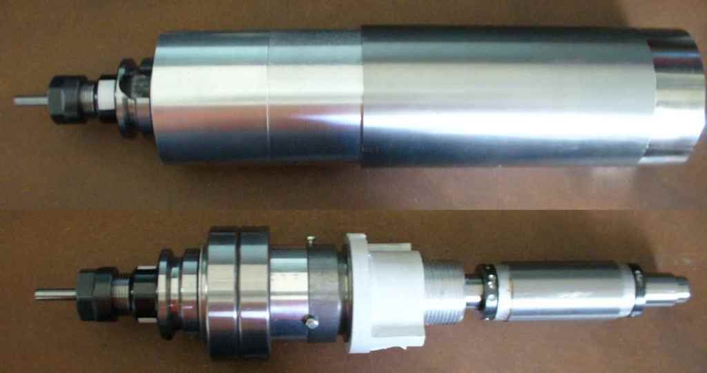
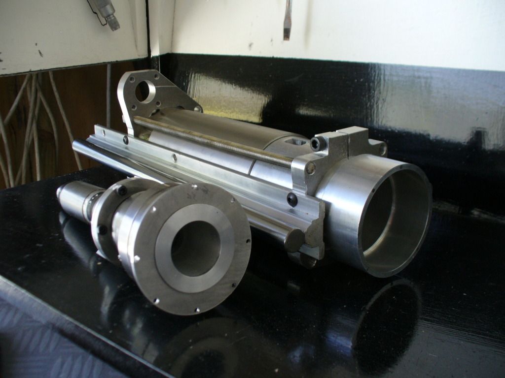
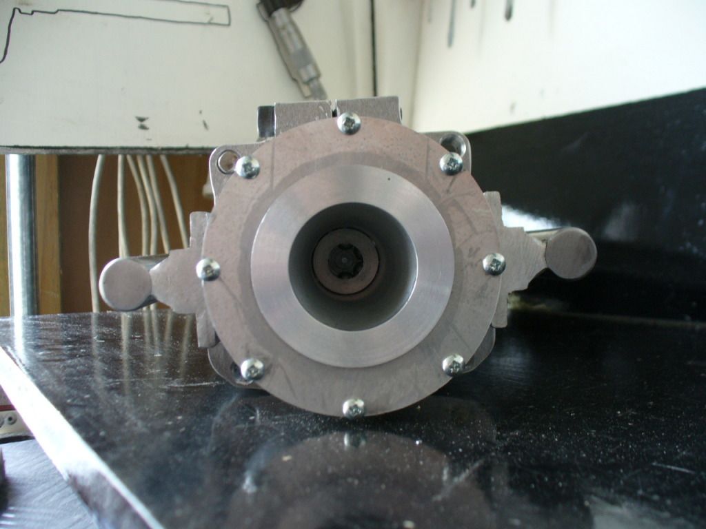
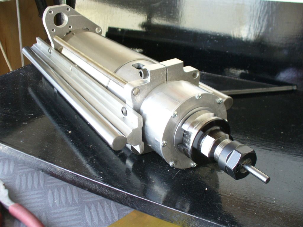
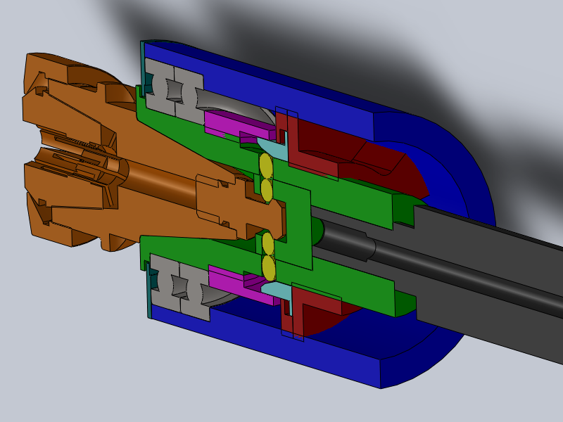
Here's a little something I put together for my 80mm chinese spindle. I guess you know the type, 20,000rpm, comes with an ER11 collet on the end.
Its only as far as proof of concept testing, but it works very well so I thought I'd share.
The retention system uses the spindle motors own drive to tighten and loosen the locking nut (which will be held in place by a simple locking pin solenoid).
First I'll get the overview shots out of the way...
And a few videos:
Showing the tightening mechanism at work
and the retention force
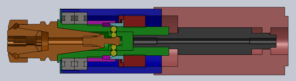
Now the working principals.
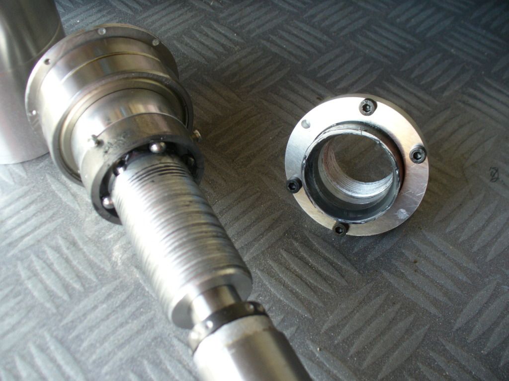
Taper (green), toolholder and stub (bronze), locking balls (yellow), locking nut (red), and locking wedge (light blue) are the ATC parts. The rest is all pretty standard stuff.
Between the Taper and locking nut is a 2mm pitch thread. The locking nut has two drive (locking) dogs which (with a pin) lock the nuts rotation to the housing but allow it to move up and down the axis. This enables the locking nut to both pull and push the locking wedge up and down the spindles axis. When the locking taper is pushed down, the forces the balls inwards, which presses the tool holder stud upwards due to the contact angle. The tapers on the tool holder stud mean when the locking wedge is removed it will push past the balls easily.
I can upload CAD files, and give more detail on the manufacture (order of operations is important to reduce runout) if people are interested.
On a personal note, I reckon this is good enough to put into manufacture and go to hardened steel parts instead of aluminum like I used. However I'm a bit low on time an money so I'm just making it open source instead. Of course if anyone else wants to make one or more for yourself or others, just go for it. And if you think the designs are worthy of a donation PM me for paypal details, it'd be nice to afford more than one tool holder for my ATC setup
Similar Threads:
Last edited by bogan; 10-06-2012 at 01:29 AM.

This looks fascinating. I for one would like to see the drawings.
Art
AKA Country Bubba (Older Than Dirt)
bogan
Don't up load your drawings Here, You should sell them, then you can buy your needed tool holders, there is enough in what you have shown for a good machinist to make the ATC, with what you have already posted
Mactec54
I'd be interested in buying one if the price was right. You have any ball park idea on what you spent?
How about a group buy?
My CRP 48 x 48 build [URL=]http://www.cnczone.com/forums/open_source_cnc_machine_designs/144173-crp_4x4.html[/URL]
Ditto here. Although, my spindle has an ER20 collet.Originally Posted by vtx1029

There are a lot of projects on Kickstarter that don't seem like the belong. This wouldn't be one of them.
You should absolutely try to make a small business out of this idea or sell the idea to someone. CNCRouterParts might be a person to contact.
Thanks for the compliments guys, but I have so many other things on the go that I am more equipped to make a proper job of, so I'm happy to let this one go.
The kickstarter idea is a good one, except NZ'ers can't register. If somebody over in US wants to take it on as a kickstarter or whatever, just budget in a healthy sum to pay me for the design/experience/manufacturing tips I would provideNot that you would need to pay as I'm giving it away freely anyway,. but what goes around comes around right!
Cost for that one is hard to say, maybe 50 bucks of metal stock, and 50 bucks of bearings and fasteners. But its a proof of concept model, the next ones should be made out of good steel, have the taper ground instead of cut, and be hardened afterwards. The bearing size is the same as spindle grade angular contact which are capable of max rpm (the deep groove I used will only be run to about 8k).
One thing it isn't so good at is tool release, as there is no mechanism to push the tool holder out. Solvable from the tool changer mechanism though.
Would make a few changes in design and machining process if I was doing another, but nothing major.
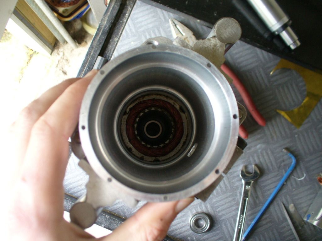
And with regard to the original chinese spindle, the rotor needed the end machining down to a press fit (mine took 8 ton to press the taper on so I think its pretty tight). The ATC housing needs rods running right to the top to bolt it together, as the standard threads are inaccessible when assembled.
I would think a final price between 500 and 1000 would cover it? but would depend on economy of scale a lot. Not sure whether the spindle rotor would get pressed on during the process, which might make it difficult to harden the steel properly, or pressed on afterwards, which might cause alignment issues.
Its all the little things like that which actually makes it a significant distance between the proof of concept above, and a production unit I'd consider good enough quality to sell.
Sent an enquiry on CNCRouterParts' site. Will look at uploading the design files today, might end up over the size restrictions though, will see.
Hmmm, worked better than expected
This is an amazing project. Thanks for sharing.
Bill
Joescnc 4x4 R&P Router, Minimill, Minilathe, CNC Foamcutter, laser cutter, Vectric Aspire. http://makermasters.com, http://themakersguide.com
Thanks heaps for making the details available! I'm sure many people here will be very appreciative. I certainly am, even though I'll probably cock it up trying to make it!
cheers,
Ian
It's a state of mind!
Cocking it up is just one way of learning. And considering this is the third new spindle I've done, I'm proficient in both
This is very cool! I have had plans to make a pneumatic atc for my machine. I'm still getting everything sorted out on my cnc, and I have a few projects to do first. Maybe one day soon I'll have time to make one.
By popular request (and in exchange for beer money), here's an igs of the spindle.
Thanks and enjoy one on me!
Hello
Very interesting design. How do you get enough torque out the spindle motor
to tighten and loosen the nut? Also, it seems that balancing the whole assembly would be a major problem.
Larry
The torque required is actually very low due to the thread pitch, and angle on the taper that drives the balls in.
Balancing could be done as normal will material drilled away where required, the only unbalanced parts will be the threads, which is common across all spindle designs I've seen.
Hi, as this project continues that evolution has had? that performance?, forcing Nm is achieved with the system of spheres in the holder, until it has been possible speed (rpm?), aluminum chassis in steel?
Considering making one for my 24000 rpm spindle. In steel. I'm hoping for a hand as I go.
Post how things are going in this thread and I'll offer advice as I can.
I still haven't got around to doing a proper ATC implementation on mine, just haven't spent the time bringing spindle rpm and locking solenoid under mach3 control. Had to take it apart last weekend as an internal locking collar had come loose, it all looked fine otherwise though. One enhancement I would make would be a second set of balls on the top side of the pullstud to force the tool holder out of the taper; it could be a bit hit and miss otherwise.
tried down loading and unpacking but win rar keeps saying the the file headers are corrupt?
any clue? same for the solidfiles
jh

")

