table rocks when reversing x travel - Page 2

Page 2 of 3 FirstFirst 123 LastLast
Results 21 to 40 of 42

Thread: table rocks when reversing x travel

  1. #21
    Registered
    Join Date
    May 2006
    Location
    USA
    Posts
    16
    Downloads
    0
    Uploads
    0

    Default

    Dahui,
    I figured out something helpfull on my Tri-Power for reducing the table rotation around the z-axis. Having noticed the rotation when boring a hole on the lathe and then reading this thread I decided to try and quantify how much rotation my machine had and why it happens.

    I set up a test indicator on a magnetic base on the table indicating on the outside circumference of the lathe 3-jaw chuck at the lathe center-line above the table so I could move the table in x and read the y movement.

    Starting at the right edge of the chuck I moved the table left about .1 inch and zero'd the indicator. Further movement to the left showed no indicator movement as expected. Reversing the table movement to the right showed about .005 movement away from the chuck that then stayed at .005 with further rightward movement. Moving the table back in the leftward direction brought the indicator back to zero repeatably. The reason for this movement is rotation of the saddle in the x dovetails driven by torque from the offset lead screw reaction with the friction of the dovetails. Properly adjusted gibs SHOULD eliminate this rataion.

    Note that when I measured the .005 displacement the left edge of the table was about 2 inches from the face of the chuck. The reason I point this out is because I believe the table is rotating about the intersection of a line drawn from the back left to the front right with a line from the front left to the back right of the dovetails. So if you move the table under the chuck and make the same measurement the displacement is much less because you are closer to the center of the rotation and the y component of the rotation is less because of the angle.

    Now for the hopefully helpfull tip. When you move the table from right to left the offset acme screw causes the table to rotate clockwise. The rotation is limited when the rear right dovetail edge and the front left gib strip edge come in contact with the ways. At the same time, the rear left dovetail and front right gib strip are actually pulled away from the dovetail. When you reverse the table direction the opposite happens. This can be used to advantage when adjusting the gibbs!

    So the trick is to tighten the right gib strip after moving the table to the left and the left gib strip after moving the table to the right. Using this method I didn't have to snug up the gib at all to get less than about .0003 of displacement using the above measuring method. In retrospect I can see why I had trouble adjusting the gibbs before. If you adjust the left gib after moving the table to the left it will be to loose and vise versa.

    I do have to mention that after using this method the table will run very smoothly and correctly for much of its travel but the last 5 inches or so by the lathe chuck will be a little tight. Tightness causes excessive x slop. Not to impressive for a brand new machine.

    good luck!


  2. #22
    Registered dahui's Avatar
    Join Date
    Dec 2005
    Location
    USA
    Posts
    183
    Downloads
    0
    Uploads
    0

    Default

    Hi,

    Thanks for the tips. That's actually the technique I used to adjust my gib but I can only get it down to about 1.5 thousandths and I have to tighten the screws so much sometimes the table sticks and jumps when I move it.

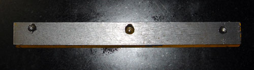
    So, I went back to take a look at the actual gib. I've already straightened it and lightly lapped it...just a polish. However, when I pulled the gib this time I noticed that the countersinks are drilled on an angle. I would imagine this could cause a problem and prevent the gib from being adjusted correctly. Any thoughts? Looks like my next project is to make a new gib and see if that helps.


  3. #23
    Registered
    Join Date
    Jan 2005
    Location
    SoCal
    Posts
    224
    Downloads
    0
    Uploads
    0

    Default

    Quote Originally Posted by dahui View Post
    .... However, when I pulled the gib this time I noticed that the countersinks are drilled on an angle. I would imagine this could cause a problem and prevent the gib from being adjusted correctly. Any thoughts? Looks like my next project is to make a new gib and see if that helps.
    Probably making a new gib would be a good idea anyway.
    But, the countersinks need to be inline and square with the adjusting screws...
    -not perpendicular to the gib.

    Once you get the gib machined (with the 55-60 deg edges) its probably best to locate each adjusting screw, one at a time, to ensure your countersink lines up properly.
    i.e. its gotta be right under the screw - no matter where the screw is located.

    also, consider using brass or bronze instead of steel?


  4. #24
    Registered
    Join Date
    Mar 2006
    Location
    USA
    Posts
    20
    Downloads
    0
    Uploads
    0

    Default

    Found some interesting things in my research the past few weeks. First, I found that most of my play was in the end nuts just up from the X-Axis handle. (Picture Shown). It was loose just enough to be aggravating. Next, I measured all the ball bearings in my ball screw and found that they were all 0.001" or more shy of 0.125" (Picture #2 shown). I purchased 70 new ball bearings from a bearing supplier here in town that was much closer. I measured a consistent 0.1248" on each ball. This seems to have fixed my error on my cuts. I still have great tolerance on the Y and Z axis. I have a practice part made of wood shown below, showing better tolerance in each pass of the cuts.

    Attached Thumbnails Attached Thumbnails table rocks when reversing x travel-backlash-002-jpg   table rocks when reversing x travel-backlash-009-jpg   table rocks when reversing x travel-backlash-011-jpg   table rocks when reversing x travel-backlash-003-jpg  

    table rocks when reversing x travel-backlash-004-jpg  


  5. #25
    Registered
    Join Date
    Mar 2008
    Location
    usa
    Posts
    10
    Downloads
    0
    Uploads
    0

    Default

    Quote Originally Posted by dahui View Post
    Hi folks,

    I've noticed that my table rotates/rocks slightly when I change directions while traversing the X axis. Okay okay, adjust the gibs right? I've posted on the shoptask delphi forum as well but despite some good advice I can't solve the problem.

    Okay here is what I've tried...I pulled the gib strip and checked it with a parallel. I found the center was higher than the ends. I put a steel rod in the mill, blocked up the gib at both ends, and used the rod to push down in the center of the gib (gently) untill checking with a parallel showed the gib to be more or less flat by eye, looking for a gap or rocking of the parallel.

    I sanded/polished the gib and looks like I'm getting about 80% contact. I reinstalled the gib with the locking handle totally loose. Then I would put tension on the adjustment screw and work the table in the +/- X direction while snugging the screw. I went back and forth between the two adjustment screws with this method.

    The best I could do is a .002 variance between +/- X travel. To test this I chucked a steel rod in the lathe and attached my dial indicator to the table and put the indicator up against the rod. I used this while adjusting to see if I was making any progress. Even by tightening the gibs "a lot" I couldn't get the wobble out. It seemed that I could achieve the same .002 variance with light pressure on the adjustment screws and the table moving very smoothly.

    At one point I cranked the locking handle down hard, loosened it and then moved the table +/- X. I was shocked to find that now I was seeing almost .030 variance. I went back and adjusted the gibs with "firm" pressure on the locking handle instead of loose. I can get back to .002 variance but no better. I was wondering why the ball turner I made slides perfecly in the slot and then gets stuck...this would explain it.

    Any thoughts?! Thanks in advance. One thing I did notice is that if I look at each end of the gib (when it's mounted) one end is flush with the casting on the bottom and the other end of the gib rides higher than the bottom of the casting. To me this says the indents for the adjustment screws and the locking handle are not parallel to the edge of the gib...could this be the problem?
    Dahui, you aren't the only one with this issue, I've been struggling with it for a year.

    If I move the crosstable forwards towards the spindle and stop, put indicators on both ends of the crossbed and then move backwards in X, I can measure the rotation - similar to yours of about .002 to .004 Once the rotation is "complete", the table moves smoothly down the x -axis. If I stop and reverse, again you have rotation, it stops and now you are moving the other way. I've tried everythin I can think of and while I've made it better, I can't get rid of it, and if you are doing precision work, it can ruin your piece. John has been little help, just keeps telling me to straighten the gib (which is dead straight at this point) and look for high spots on the ways. Also, if I try using the gibs to solve the problem, movement becomes difficult and worsens the other problem I have of the movement of the crosstable in X (down towards the spindle) is uneven, easy at the tailstock, harder near the chuck.

    Now for the experts (Ie; not me), what do I do next? Are my ways warped/twisted? That would explain the problem in feel as I move from 1 end to another, but how do I tell for sure?
    And what's causing the rotation? The gib strip is dead flat, checked against a granite plate. In order to pivot, something has to be allowing the crosstable to "wriggle" where the design would suggest such rotation should be zero.

    If anyone can help me figure this out, I'm more than willing to put time and effort into it, I need some info on where to put my effort. All assistance greatly appreciated!!


  6. #26
    Registered
    Join Date
    Nov 2007
    Location
    usa
    Posts
    277
    Downloads
    0
    Uploads
    0

    Default

    It might be that your dove tail on the lathe bed is machined wrong. Or that at the bottom of the dovetail their is some part of the casting that is causing the problem. Today I removed all the paint from my lathe bed then I could see where they had to ground away metal from the bottom of the dove tail of the casting. They had body filler then a coat of primer and the several coats of the yellow lead paint. They didn't even take time to remove the casting sand. It was imbedded in the paint. I had to use paint stripper and then oven cleaner to get everthing off. I am priming the casting and I will post pictures as soon as I can and show where they had ground to prevent the ways from touching the casting. You might try blueing the ways to see if their is high spots. You can buy persian blueing at Napa . It come in handy when you have these kind of problems.


  7. #27
    Registered
    Join Date
    Jul 2005
    Location
    usa
    Posts
    151
    Downloads
    0
    Uploads
    0

    Default

    Bprager,
    I had a similar issue with the used machine I bought. I went through the gib strip inspection processes with JT's help on the phone, but I found the problem was a hard spot in the casting where the dovetail was machined. If you are experiencing the same rocking through the full carriage travel, then the source of the problem would be in the moving part. On my machine there was a small spot about the size of a dime that was really hard- possibly a piece of hard material that was not fully melted during the casting process. When they machined the dovetail, this spot simply didn't cut like the rest of the casting and made a high spot where the table would rock around it. I was going to send it out to be ground, but decided that it represented only a small percentage of the total surface area, so I just used a carbide burr to grind it down. Using some blue and emery cloth over a file I made sure the high spot was gone and the dovetail was flat.
    That took care of the problem.


  8. #28
    Registered
    Join Date
    Jul 2007
    Location
    USA
    Posts
    195
    Downloads
    0
    Uploads
    0

    Default

    PUT A MATCH BOOK UNDER THE SHORT LEG

    Be carefull what you wish for, you might get it.


  9. #29
    Registered
    Join Date
    Aug 2008
    Location
    USA
    Posts
    17
    Downloads
    0
    Uploads
    0

    Default

    Hello everyone,
    I have been a member here a few times over the last few years,(Lost passwords and changed e-mails) and post very seldom ..
    Shows how observant I am , I noticed a shoptask thread here,,
    I had the old 1720 then wanted to go into CNC and bought the Bridgemill back a few years ago and seem as though I have had all of the same problems with mine as you all are posting on here..
    I added ballscrews and dro on mine when I purchased it.. The DRO is the older one with th ratcheted rail on it so it skips steps all the time now and finally found he problem ends up being the little spring steel bracket that holds the encoder needs to be soldered to keep it from slipping off, but thats just one of the things I have found,,
    Tramming the mill can be close to impossible with the amount of play that are in the gibs on this mill..I found a website (not sure where now) that was polishing the gibs for a Seig X2 mill by taking the mill down washing it down and putting lapping compound on the rails and gib and lapping the compound back and fourth for a hour and keep changing it and cleaning it until both the gib and rails are smooth.. I have not taken the time to do that with mine, But need to but the idea of taking the y axis off with the ballscrews does not sound fun to me, its summer in my garage and not enough fans in the world keep it cool ..
    The Z axis ballscrew mount from the factory is just satisfactory , what I found is that the plate that they use to connect the quill to the servo and ballscrews has a tendency to shift or flex so that need to be replaced as well or re-designed...
    I have only been able to get a few simple satisfactory parts made on the mill , but I don't use it very often any more but I am getting ready to use it to build some parts for a wood router so I need to get it back into shape so I can finish the parts.....
    Man what a long winded first post and sounds like I was crapping on the shoptask but , I do like the mill it is solid it just needs to have things done to it to make it more accurate..
    Thanks
    Gary V

    Last edited by GaryV1959; 09-12-2008 at 02:00 PM.


  10. #30
    Registered
    Join Date
    Feb 2009
    Location
    usa
    Posts
    87
    Downloads
    0
    Uploads
    0

    Default

    What did you guys do to fix this problem or did you decide to live with it??? I have the same problem but beleive it is not due to the gibs or ways themselves.

    The table saddle on the "x way" is flexing. More exactly, right where the gib adjustment screws are mounted on each side. I started by cleaning, flattening, and adjusting the gibs. I locked down the "y way" and mounted the base of a dial indicator on the table. I put the dial indicator right beside one of the gib adjustment screws and moved the table assy one way then the other. I read deflection of .0015 on one side and .001 on the other. This totals to give me the rocking of about .003 when measuring off the chuck.

    What can I do to fix this or is this just part of having a Shoptask? I have the older Gold Series with a self built lift.


  11. #31
    Registered
    Join Date
    Mar 2008
    Location
    usa
    Posts
    10
    Downloads
    0
    Uploads
    0

    Default Table rocking.......

    Quote Originally Posted by banctecbobn View Post
    What did you guys do to fix this problem or did you decide to live with it??? I have the same problem but beleive it is not due to the gibs or ways themselves.

    The table saddle on the "x way" is flexing. More exactly, right where the gib adjustment screws are mounted on each side. I started by cleaning, flattening, and adjusting the gibs. I locked down the "y way" and mounted the base of a dial indicator on the table. I put the dial indicator right beside one of the gib adjustment screws and moved the table assy one way then the other. I read deflection of .0015 on one side and .001 on the other. This totals to give me the rocking of about .003 when measuring off the chuck.

    What can I do to fix this or is this just part of having a Shoptask? I have the older Gold Series with a self built lift.
    I have NEVER been able to fix this and would love for anyone to tell me how to. My results are just like yours, and I have come to the conclusion that either the ways are slightly warped, or there is flex in the table saddle. It appears to be a design problem and have never gotten a real answer from JT on how to solve it or from anyone else. I have been living with it and try to work around it. My last gasp measure is I am making a new brass gib strip that is far better than what comes with the shoptask. It will be absolutely flat and the areas where the gib screws press against it, will be carefully made to precisely match the angle and location of the screws. The current strip has the holes all over the place. If I lightly lock in the center gib screw and tighten the right side, the entire gib rotates upwards. When I now try and tighten the left, you can see that it wants to rotate downwards.
    What this twisting force does, I'm not sure, but it certainly doesn't allow for the kind of smooth movement that you should have down the x axis and I have ball screws. Frankly, the whole X axis system and ball screw system in my opinion, is badly designed with holes that make it almost impossible to truly align everything, and with too much material overhanging areas with no reinforcement. The whole design screams flex and I think if your lucky, the one you get happens to be decent. If not, you run around trying to redesign the shoptask.
    Don't get me wrong, for the money, its not bad. But at the same time, it should be much better and it wouldn't take very much, but most of the fixes have to come from the factory and in manufacture, not after the fact.
    I'm disabled so its not practical for me to "send" anything back to JT, or even take it someplace, so I am rolling my own fixes.
    I've added new spindle bearings and a Invertor (big help in use of the system) with an automatic belt tensioning system (since the inside now has only 2 pulleys, motor and spindle). Have tachometer readouts of motor and spindle speeds, and with the new gib, I hope to at least get less rock, and smoother travel with the adj screws not battling each other. Added the new DRO's and a friend is going to help me change out the mill motor and bearings for attachment to the invertor and then the rest, I'm putting up with.
    If you or anyone else has ideas on how to finally solve this rock, I'd love it as its the last real "problem". With it gone, the shoptask would be a pretty nice machine. It still is, but the accuracy is significantly impacted by the rocking.
    Please let me know if you get anywhere, as you are NOT the only person with this issue.


  12. #32
    Registered
    Join Date
    Feb 2009
    Location
    usa
    Posts
    87
    Downloads
    0
    Uploads
    0

    Default

    Would it be possible to make a two piece wedge gib? Something like door shims, two tapered gibs that when pushed in would exspand, when pulled apart would contract. This would spread out the load that is put all on the tips of two adjusting screws.

    Something to kick around.


  13. #33
    Registered
    Join Date
    Nov 2007
    Location
    usa
    Posts
    277
    Downloads
    0
    Uploads
    0

    Default

    There is a slight taper on the ways from front to rear. I have tried to lap the table to the ways. I will know in a few days if it helped. I will start putting everthing together soon.


  14. #34
    Registered
    Join Date
    Feb 2009
    Location
    usa
    Posts
    87
    Downloads
    0
    Uploads
    0

    Smile

    I beleive the ways are fine......... we have different machines. I can disconnect the lead screw from the table and push it back and forth with the same drag from end to end except for the very last couple of inches on the right end.(farthest from spindle) This is a good way to find/feel for high spots. I get my rotation or deflection when I first change directions. I only have one dial indicator but it seems/appears to rotate then move. It does not rotate more or less as the table travels in the "x way", only at directional changes.

    I tore the table assy apart a couple hours ago and I really think there would be alot to gain from reworking/redesigning the gib setup. I'm not a machinist and have no other experience with other machines and their gib setup. From glancing at machines in the stores it seems some use a single tapered gib. I assume the dove tail is cut in an angle. Is this so??? Any help or suggections would be great. What would be the best material to use for new gibs?

    I would also like to mount the acme nut assy directly to the bottom of the table saddle and get rid of the "L" bracket mounting.

    I've not used the Shoptask for 7 years but now I have a new project and would like to try and fix this thing while I get brave enough to buy an Industrial hobbies mill.

    Last edited by banctecbobn; 04-13-2009 at 12:56 AM. Reason: wording


  15. #35
    Registered
    Join Date
    Jan 2008
    Location
    usa
    Posts
    458
    Downloads
    0
    Uploads
    0

    Default

    Quote Originally Posted by fastlanecafe View Post
    I had a similar issue with the used machine I bought. I went through the gib strip inspection processes with JT's help on the phone, but I found the problem was a hard spot in the casting where the dovetail was machined. If you are experiencing the same rocking through the full carriage travel, then the source of the problem would be in the moving part. On my machine there was a small spot about the size of a dime that was really hard- possibly a piece of hard material that was not fully melted during the casting process. When they machined the dovetail, this spot simply didn't cut like the rest of the casting and made a high spot where the table would rock around it. I was going to send it out to be ground, but decided that it represented only a small percentage of the total surface area, so I just used a carbide burr to grind it down. Using some blue and emery cloth over a file I made sure the high spot was gone and the dovetail was flat.
    That took care of the problem.
    The above explanation from another owner is most likely correct. Cast iron is not subject to a lot of flex, and the thickness of the casting would be more than a person could flex by hand. I suggest that you disconnect the lead screw, clean the gib strip and the carriage as well as the casting with some brake cleaner, and then put machinist blue on the carriage top and dovetails. Move the carriage the full length of the bed and look for any shiny spots where the ways might be high.


  16. #36
    Registered
    Join Date
    Feb 2009
    Location
    usa
    Posts
    87
    Downloads
    0
    Uploads
    0

    Default

    Smallblock,

    You make a good suggestion, but the table/saddle assy has a measured flex/movement within itself.


  17. #37
    Registered
    Join Date
    Nov 2007
    Location
    usa
    Posts
    277
    Downloads
    0
    Uploads
    0

    Default

    I had a friend make me new way strips for me. The old ones were to thin and had to much gap between the table and the strips. Now they just barely fit. I believe that the strips were shifting because of the excessive clearance .


  18. #38
    Member
    Join Date
    Feb 2009
    Location
    usa
    Posts
    281
    Downloads
    0
    Uploads
    0

    Default

    Quote Originally Posted by digitalmdj View Post
    I had a friend make me new way strips for me. Now they just barely fit. I believe that the strips were shifting because of the excessive clearance .
    Thats a good point. We found one machine that didn't respond to adjustment the way it should. After removing the bed wipers, we could see that the gib strip was a bit too wide and when the adjuster screw was moved in, it moved upward and wanted to raise the carriage off the ways. This may be the problem with the other guy's machine too, as I can't imagine the casting flexing. I let the kids do a brainstorming session just to check their problem solving skills. First, they removed the gib strip and put it on a surface grinder to reduce the width and also to make sure it was completely flat. The raising was caused by the cone point on the adjuster screw not being perfectly on center, so as the screw turned the tip would raise and lower the gib. The dimples in the gibs are done with a drill, and are meant to accept the cone point, but it really doesn't give the proper pressure. I told the guys to devise a solution that could be done with the machine itself. Their idea was simple and clever. They took an 8mm bolt and chucked it up, faced the head and center drilled it. Then they drilled it and reamed it to 3/16". With the gib strip in and held by the other adjusters, they threaded the bolt into one hole and used a 3/16 end mill to make a flat bottom dimple in the gib. Then they turned the original adjuster so it had a 3/16 dog point on the end. The process was repeated until all the gibs and adjusters were done. Now, the adjuster screws fit into the dimples and have a much larger pressure area. The whole process only took a couple of hours once the plan was in place. It was a good exercise in problem solving and the kids met the challenge.


  19. #39
    Registered
    Join Date
    Feb 2009
    Location
    usa
    Posts
    87
    Downloads
    0
    Uploads
    0

    Default

    That sounds like a good fix. Never liked all the gib pressure on the points of the adjusting screws. How many adjusting screws does the newer machines have on the X way gib. I have the older Gold series and it has just two adjusting screws. Would it be advisable to drill and tap for additional adjusting screws?


  20. #40
    Member
    Join Date
    Feb 2009
    Location
    usa
    Posts
    281
    Downloads
    0
    Uploads
    0

    Default

    Quote Originally Posted by banctecbobn View Post
    That sounds like a good fix. Never liked all the gib pressure on the points of the adjusting screws. How many adjusting screws does the newer machines have on the X way gib. I have the older Gold series and it has just two adjusting screws. Would it be advisable to drill and tap for additional adjusting screws?
    The Patriot machines have 4 adjusters and 1 center lock on the Y axis.
    X axis and tailstock have 2 adjusters and a center lock
    Because the Y table is the longest piece, it is subject to the greatest leverage- adding more screws to the older machines might improve them.


Page 2 of 3 FirstFirst 123 LastLast

Tags for this Thread

Posting Permissions

  • You may not post new threads
  • You may not post replies
  • You may not post attachments
  • You may not edit your posts
  •  


About CNCzone.com

    We are the largest and most active discussion forum for manufacturing industry. The site is 100% free to join and use, so join today!

Follow us on


Our Brands

table rocks when reversing x travel

table rocks when reversing x travel