Hi Luthor,
A friend in Sydenham is badly in need of a manual.
Would it be possible for him to contact you?
I can give/get details by PM.
We are debugging his machine, and might be able to help with yours.
Thanks, in advance.
Neil


I have a Compulathe that has been working well with the ANCA control until it died a few weeks ago. The maintenance manual lists a few things to check or try when the green watch dog light on the "single board" is not lit but nothing has worked so far.
The manual mentions checking the "start up circuit" but provides no detail of where on the board it is or how to check it.
I am hoping that someone with a similar machine may be familiar with the ANCA single board and may have come across this situation before and have a diagram or other information on the start up circuit area of the board.
Similar Threads:
Lex
Hi Luthor,
A friend in Sydenham is badly in need of a manual.
Would it be possible for him to contact you?
I can give/get details by PM.
We are debugging his machine, and might be able to help with yours.
Thanks, in advance.
Neil
Last edited by neilw20; 05-27-2012 at 01:41 PM. Reason: typo
Super X3. 3600rpm. Sheridan 6"x24" Lathe + more. THREE ways to fix things: The RIGHT way, the OTHER way, and maybe YOUR way, which is possibly a FASTER WRONG WAY!
Hi Neil,
No problem contacting me (0401243342)
I can scan or copy the manual if required.
Lex
Hi guys,
I replaced the 4n35 and now i det the red LED come up. Never had that before, still got the solid cursor on the screen though. Don't know what this LED is/does/indicates. When "Reset" is pressed, the led goes out briefly and then turns on, i take it another part of the circuit is not working.
At least you are getting something now Anthony. The red LED indicates power failure, what that means exactly I don't know. What position are the switches on the board in?
Lex
Thanks Lex,
I'll have to go through and check all the test points and IC's for power. Here i am in the garage working on this nice machine (since Sat) and the only joy so far is a single LED hahaha talk about a tease!
The switches all point towards the reset switch
Lex,
FYI
Cheap, inexpensive treadmill motors fit electrically (180V) and size wise into the lathe, i just machined the shaft on one and fitted it up, 2.3HP cont 3HP peak. nice, smooth and strong. Not that taking more meat off per cut is the aim, but spindle speed not hunting while threading and the like. My machine does not have the ANCA controller and as such has been "converted" to steppers ........ for nowEverything removed from this machine can be put back into it in an hour.
AS for the Mill with ANCA dud controller...... still no joy....
My machine is up and running again after repairing an open circuit, between D63 and pin 1 of opto, caused by corrosion.
Lex
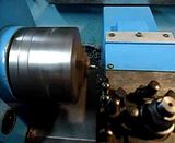
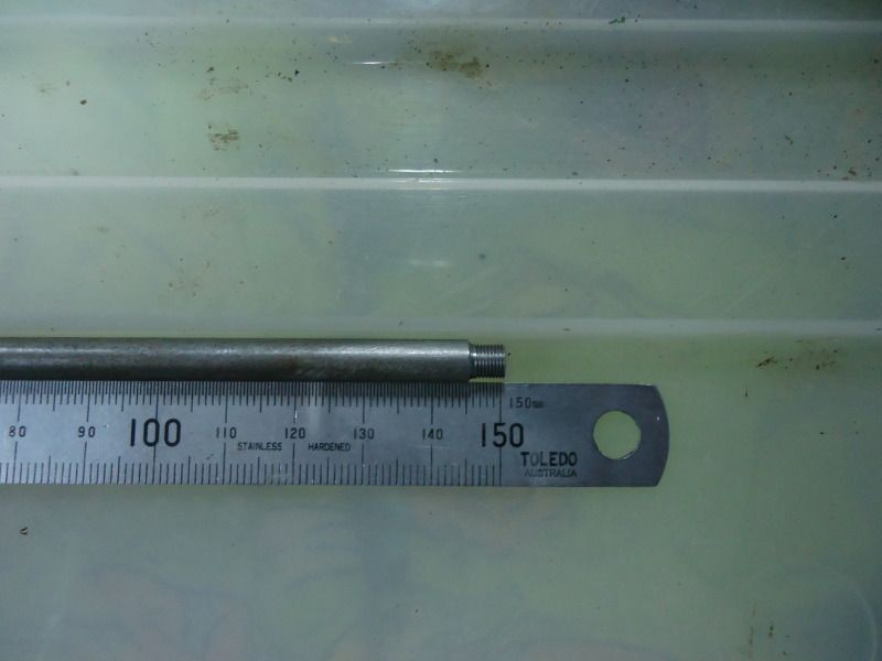
A poor quality video and photo of the parts I have been screwcutting on the Hercus. M5 x 0.5mm at 1000rpm.
Click on Video.
Last edited by lsd0; 06-03-2012 at 07:58 AM.
Lex
The switches all point towards the reset switc
For anybody having trouble with the ANCA controls, you should contact Ultra Logic Systems - Ultra Logic Systems - Home
The Red LED near the middle of the board does not indicate a power failure, it indicates a Time-Out, which means in simple terms that the computer has stopped working because of 'something'.
Glad to hear you've got things moving their Radiola
Hi Lex, Neil, and Grant!
I have got the lathe working with the steppers and all that's left are a few little things to tidy up. now i am having a basic run through the Mill (With the ANCA 2000 controller).
I have never been up there with digital - more an analogue man. In saying that i have determined the following:
1) All my CS inputs are constantly high
2) The clock signal on the output of the 8482 is at 5MHz (one 3rd of the xtal of 15MHz).
3) "Activity" happens on the address lines of the eproms and there are 'no shorts'
4) My processor is "working" as but as Grant suggested it is "waiting" for something -what? i do not know!
5) The TP1 voltage can be altered via trimpot on little floating board within Lamron PSU. Now is between 0.200 and 0.250v.
When i first got the machine, i had NO RED Led, all i had was noisy fans and a solid cursor. I discovered that the 4n35 was knackered and I replaced the 74C14B Hex Schmitt Trigger and the clock signal appeared on the output of the 8482. I am now sure the startup circuit is working as per sheet 421!
I don't yet know enough about the flow of 'events' to know what to look out for next. I'm currently weighing up the pros and cons of retrofitting the machine but i'd hate to go to that trouble just for one dud part, or solder joint.
in the mean time i'm happy learning and tinkering and will update if a break though is found.
Cheers
Ant
Do you want me come and fix it?
Hi Anthony,
There isn't any 'startup circuit' as such, despite what the Hercus manual may say. Best to leave the power supply pot where it is, depending on which pot you are playing with that will only affect the voltages (eg. +5V, etc.) or the Power fail trip point, which you really don't want to play about with.
TP1 is fine at 0.2V, that's not your issue.
It's an 8284 you're talking about and that will likely be fine, your problem will be the corrosion as I mentioned when Nigel and I was over there. It may be just tracks, it may have gotten into some of the chips, but either way it should be cut out properly and fully or it will just come back to haunt you - guaranteed!
The 4N35 will have failed due to the corrosion - very common, but replacing that won't fix the cause of course.
The Red LED near the middle of the board is not supposed to come on, that's the Time-Out LED which means the computer has failed (actually a Non Maskable Interrupt). The problem is that many of those LED's were fitted backwards in the factory, so it may not come on even when it's supposed to, unless it has been corrected on your board. If there is an Orange LED near the battery (an Ultra Logic modification), that is supposed to be on and in basic terms indicates 'Power good'. Many people mistakenly call that Red, but there is a real Red LED closer to the Green Watchdog LED.
I'm biased, but I still think your best bet is to stick with what you have, Nigel doesn't have that bias but has owned several of those machines for probably 10+ years, and he said the same, so I think that's a good indication from someone who has run with them for many years.
haha
Is the pope Catholic?
Does he drink Crownies?
Hi Grant,
I agree with what you say there and for those that know me (or know what other hobbies i have) know how i like to keep things original. Not long after your visit, this thread was started by Lex who had the same symptoms and the same corrosion problems as my mill. I thought that i might be able to try the simple things he did but as luck would have it, my board must be affected worse than his.
So at this point it's back to the 'weighing up' stage. Granted the original controller is worth keeping, but what if something else fails then i am back to square one with hands tied behind my back, after all it was built before my Mrs was born hahaha
I can't argue about the age, but I can say take it from somebody impartial who has had 5 or 6 of them going for about 10+ years (Nigel) and listen to his experiences.
It's a bit like your fridge or the radios, most people would laugh, but you know they're worthwhile.
Read the PM I sent you and see what you think. I'll do what I can to assist.
- Oh I forgot to mention in my PM that a beer or two would have to be included
Cheers!
Try a PM to: https://www.cnczone.com/forums/members/radiola.html
Super X3. 3600rpm. Sheridan 6"x24" Lathe + more. THREE ways to fix things: The RIGHT way, the OTHER way, and maybe YOUR way, which is possibly a FASTER WRONG WAY!