


 Reply with Quote
Hi CNCtronic,
This seems reasonablePINs 8-9, 10-11, and 12-13 are occupied by STEP & DIR axis 0,1,2 respectively
For devices with long wiring going all over a machine like limit switches, EStop, etc. it is better to use industry standard optically isolated 24V signals. Common GND TTL signals often pick up noise and may cause problems. Consider using one of our Konnect boards. Or creating your own Opto Isolated 24V Interface.
There isn't any best pin. EStop is handled in software so it can be connected to any input.What is the best PIN for ESTOP?
Similarly Limit Switches are handed in Software and can be configured for any pin.What are the best PINs for Boundary switch?
KFLOP LVTTL IO can all be configured as Inputs or Outputs.What are the best PINs for general purpose Input?
What are the best PINs for general purpose Output?
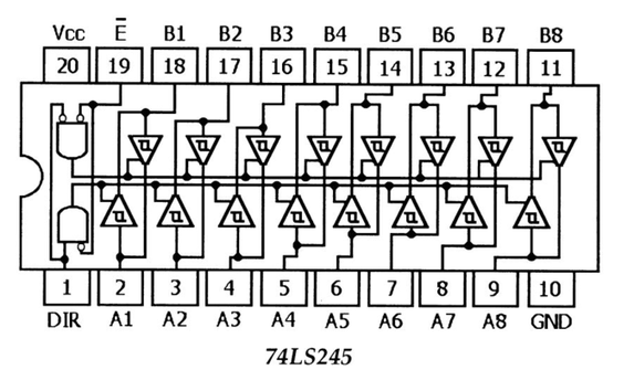
I don't really understand the purpose of this or what you are trying to do. The IO levels of 5V TTL and 3.3V LVTTL are basically the same. > 2.4V high and < 0.4V low.Right now I have a DIY board with old 74LS245 In/Out TTL Buffer as Level translator for I/O (I can chose whether IN or OUT 8 bits at a time - 3.3V to KF in, 5.0V from KF out) connected at JP7 only and i need make a design for complete board for all IN-OUT PINs.
One advantage would be that the 74LS245 inputs would be ok with a direct short to 5V where KFLOP Inputs should not be shorted to +5V if that is what you are planning. Note that 5V TTL Outputs signals can be connected directly to KFLOP Inputs as they drive with little current above 3.3V.
A 5V buffer can helpful when driving Step/Dir drives with 5V Opto Inputs. KFLOP Outputs can directly apply 5V to a 5V Opto by sinking to GND, but when turning off, the Output will only float to ~ 3.8V before being clamped. This results in ~ 1.2V to the Drive's optocoupler. This usually works fine as an optocoupler needs at least 1.4V before even beginning to start to turn on. A 5V TTL Output can float even higher to turn off the opto further.
HTH

