

 Reply with Quote
Bob,
You wont have any problems with the rail spacing the way it currently is setup and it will be as rigid as a Sherman tank.
Jeff...


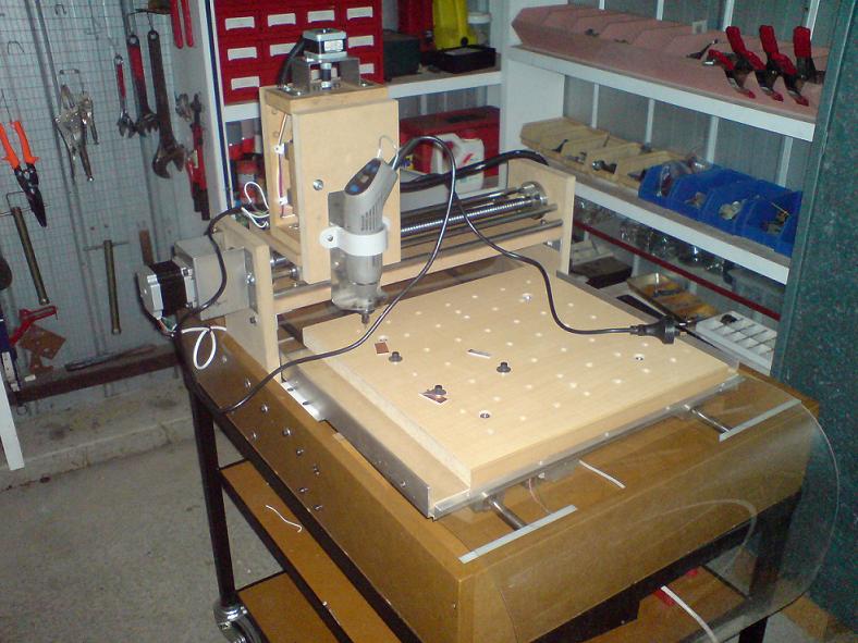
My first attempt at building a CNC router was a simple MDF one that can be seen in my display pic.
I had a couple of issues with it, the machine wasn't rigid enough, and there was too much variation in the table movement.
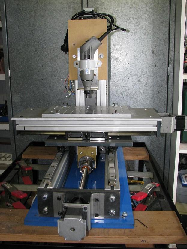
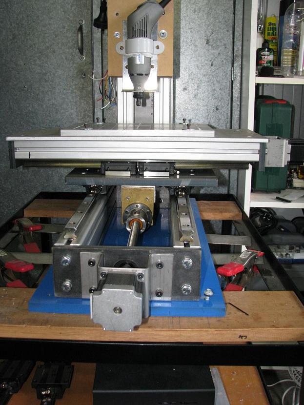
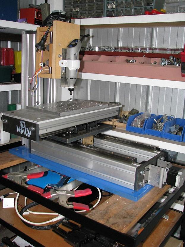
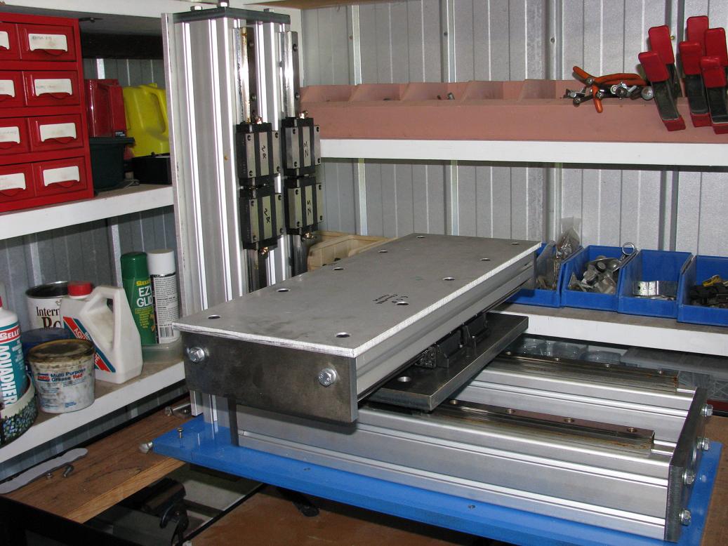
So all this lead to machine number two, which more resembles a milling machine.
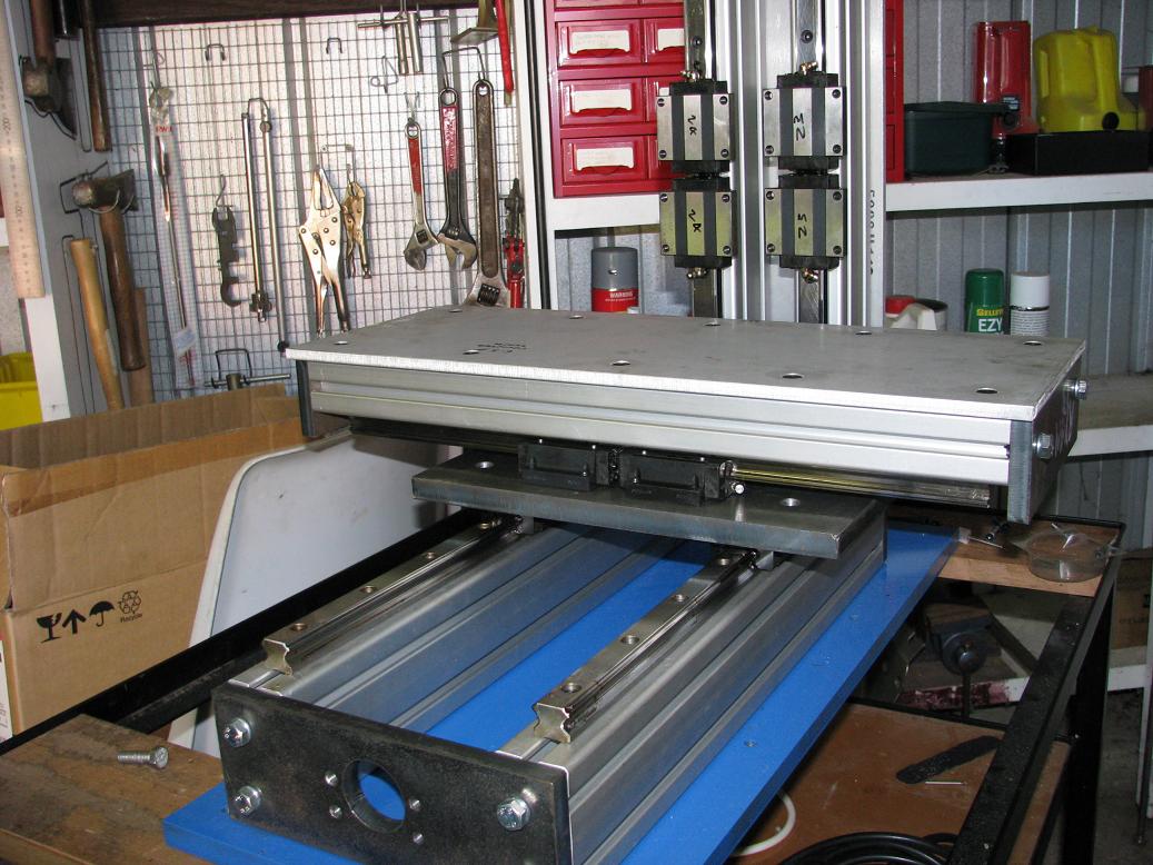
I am using linear guides (HSR20) this time as opposed to stainless steel rod with linear bearings. I am also using machined ball screws instead of the rolled ones.
Buying 2nd hand off ebay certainly has been a little hit and miss, especially with the guides. The ones I am using for my Z axis came off a machine that was lucky to travel 30mm. In turn, some of the balls are worn more than the others so movement can be a little notchy.
The guides for my X and Y are spot on and were definitely a bargain!
Travel is 100mm in the Z axis, 160mm in the X (capable of 220mm with a longer ball screw), and 300mm in the Y.
Here are some pics:
Old machine
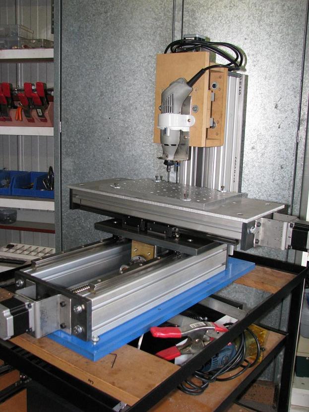
I will be paying particular attention to any movement in the y axis due to the way the bearing blocks are mounted so close together. If worse comes to worse, I will space the blocks further apart and lose some travel.
Mounting the spindle so far from the uprights is also another concern of mine, but you never know until you try, so I will give it a go and then see what improvements need to be made from there.
The base plate is 16mm mild steel, as well as the plate that joins the X and Y axis. Both have been machined parallel.
The extruded aluminium has a wall thickness of 8mm and will have the surface on which the guides sit on milled parallel also. That will be one of the last steps after building the machine to make sure I am happy with the design, before spending more money on machining.
For a spindle, I am unsure what I am going to use yet. I have a high speed spindle almost finished but it will only be good for engraving as it only uses radial bearings and not thrust.
I have been looking at those cheap Chinese spindles on ebay though with quite a bit of interest.
I also plan on building a low speed spindle with some beefy bearings.
My main use for the machine will be PCB milling, but machining aluminium is also a high priority as I am into radio controlled buggies (especially customising them!)
Similar Threads:
Bob,
You wont have any problems with the rail spacing the way it currently is setup and it will be as rigid as a Sherman tank.
Jeff...
Patience and perseverance have a magical effect before which difficulties disappear and obstacles vanish.
That looks really well built! I recently completed a gantry style router with movements in the range of X30-Y20-Z5 inches. It is nice but a little big for the desktop where I do my PCB work. I'm thinking of building a smaller unit just for PCB work, with movements in the range of X12-Y12-X2 inches. Your model looks like a path to follow.
What Linear rails did you use? It looks like you used 8020 but I'm not able to make out if it is the thick or thin wall verity.
Very nice job so far!
Here is a picture of a completed through hole board I did with my present router.
Man thats looking good. Very similar to size and design I am woking on.
What type spindle and axis motors/drives do you plan to use?
Thanks for the kind words fellas.
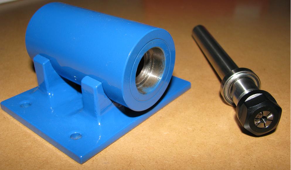
That's the basis of my high speed spindle mount (ignore the little bit of paint inside where the bearing goes!). It is an ER11 collet.
The plan is to build the same thing, but with larger bearings as well as angular contact bearings, for the low speed stuff.
Spindle drive will be via a brushless motor out of a radio controlled helicopter.
The linear rails are THK HSR20's. As for the 8020, I am not quite familiar with what that is, I only know it is a type of extrusion similar to what I use.
http://www.linearbearings.com.au/Por...ofiles%201.pdf That is a link to the stuff I'm using. I am using Profile 8 heavy (the 40x40 heavy, and 40x80 heavy). The wall thickness is 8mm. What is the thickness of 8020?
With the motors and drives, for now I will use my existing motors for the X and Y, but I can't remember the specs. I don't think they will have adequate torque though.
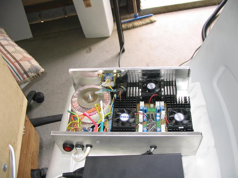
For the motor drives, I have some from the old machine that I built up which performed great.
http://secure.oatleyelectronics.com/...161af4f034f5bd - that's the drive
http://secure.oatleyelectronics.com/...161af4f034f5bd - that's the power supply to go with it.
I am running them off 35V.
The control box
The power supply
Drools, that PCB turned out really well. What sort of cutter do you use?
I like that spindle! Looks like it will have next to 0 runout.
That board was cut using a 45degree carbid bit from dertsap (Curt) He sent me a few to test. The board is 1oz copper on FR4 from digikey. After that board I did another board same bit and layout but the PCB material was 2oz copper on something other than FR4 and wow what a difference the extra copper makes! There are lots of threads in the PCBMilling section http://www.cnczone.com/forums/forumdisplay.php?f=403
I have ordered a few Professional PCB milling bits from PreciseBits and I will post some results when I get them.
I'm really interested in your spindle project! I would really appreciate it if you would document your building of it. At the moment I'm using a Wolfgang spindle and it works great for PCB only but I cannot vary the speed without jumping through some electronic hoops.
Good work!
I was trying to use a Dremel to mill my circuit boards and due to the runout, the finish wasn't the greatest. That's where I'm hoping this spindle will work well.
It was never intended to have much load on it, hence the simplicity of the design.
You should try a brushless motor out of a radio controlled vehicle. Combine that with a speed controller and you will have full electronic speed control. You can pick them up quite cheap.
http://cgi.ebay.co.uk/Mini-ER11-exte...4.c0.m14.l1262 that is a link to the collet and shank.
I like the steel end caps all around. Are you having them cut with a water jet?
Do you mean the plates on the end of the aluminium? Nah my local laser cutter cut them to size. I was getting him to put the holes in also, but the heat was warping the plates too much so now I just get him to cut them to size, and then I do the necessary machining to it.
Now that's how you get'er done! Nice job. Looking forward to seeing more of your build.
Any new updates on this one?
Nah no updates so far on this, I have been way too slack!
I go through phases of getting stuck right into it, and then it sits in the corner of the workshop under a cover
What motor/speed control combo are you using for the spindle? I know that Brushless motors draw a LOT of current while under heavy load. I'm just curious as I had this idea but ruled it out due to the current demand. Maybe you can change my mind back
Well get up on it or mail it to me in the US and I'll finish it and put it to good use.Originally Posted by bob^

Just a small update - I have the Y axis moving under its own power!
The axis had very poor repeatability, as well as accuracy. Then I realised the grub screws joining the motor shaft to the coupling were loose!
Got that tightened up and everything became spot on. Unfortunately I have 50 microns (.002") of backlash with that screw (the same as my old screws in the timber machine) so I have compensated for that with Mach 3, but I will look at getting different screws once everything is up and running (if it even needs changing)
It repeats to 10 microns too which I was happy with!
It has given me the motivation I need to finish the machine, so hopefully I will have a fully functioning x and y axis in the next couple of weeks, then just have to work out how to do the Z axis.
Any new pictures?
How did the spindle turn out?
Here is an update.
I have the X and Y axis finished, and I am using my old Z axis with the plans of using it to make my new Z axis.
The new spindle isn't together yet either, as it needs 2mm machined off one end before I assemble it.
The electrics still need to be wired up, and limit switches mounted.
My Y axis ball screw needs to be replaced sometime soon as I went to grease it up the other day and realised there is no grease nipple on the nut! There isn't even a spot for one to screw into.
So here it is!
I would bet the Y ball nut is fine but just has some gunk inside. You can clean the balls and repack them fairly easy.
It is not too hard to add some grease to them either. Lube the screw and roll the ballnut over the greased section a few times.
The dust seal can be removed by moving the nut yo the end of the screw and prying carefully then you can add grease through the end.
You could also just soak the ball nut and screw in a quart of oil over night. For light load and use like most hobby stuff you don't need much lubrication.
How did you bend the motor mounts?
I added oil to the Y axis ballscrew as a temporary measure but I still have to strip it down and give it a good clean. It's the only nut that I haven't pulled apart in the system yet to clean out.
I also have to do the bearing blocks on the linear rails, but I was too impatient to wait!
The motor mounts are 2mm stainless steel, and they were bent up on our home made sheet metal bender. Solid as a rock!
I have mounted the spindle up to the bearings and the spindle holder, and there is a fair bit more run out than what was expected.
I have 0.035mm at the collet end, compared to 0.01mm at the opposite end of the shank.
The run out is coming not from the collet, but from the collet seat.
Is that too high for PCB isolation routing? With the dremel which had over 0.2mm of runout, was getting horrible burs.