Welded steel frame router build - Page 4


Page 4 of 5 FirstFirst 12345 LastLast
Results 61 to 80 of 95

Thread: Welded steel frame router build

  1. #61
    Member jones's Avatar
    Join Date
    Oct 2005
    Location
    Australia
    Posts
    73
    Downloads
    0
    Uploads
    0

    Default Re: Welded steel frame router build

    It moves!


    Always a big thrill when a machine takes its first steps. I also fired up the spindle with the VFD and that seems to work perfectly, too!

    Still to come is to attach the Z axis, make and attach the spoil board, plumb and wire the spindle coolant pump, put all the electrics in a cabinet, mount the e-chain, then I can look at taking first cuts.

    Then finally I'll make the outboard supports for the ballscrews, add limit/home switches and remake the X and Z axis plates from 30mm aluminium.

    http://www.barberprecision.com.au
    https://www.cnczone.com/forums/diy-cnc-router-table-machines/365922-cnc.html


  2. #62
    Member peteeng's Avatar
    Join Date
    Jul 2018
    Location
    dum dum
    Posts
    6333
    Downloads
    0
    Uploads
    0

    Default Re: Welded steel frame router build

    woo hoo - always the best moment. Is the bug zapper interlocked into the router g code? Peter


  3. #63
    Member jones's Avatar
    Join Date
    Oct 2005
    Location
    Australia
    Posts
    73
    Downloads
    0
    Uploads
    0

    Default Re: Welded steel frame router build

    Quote Originally Posted by peteeng View Post
    woo hoo - always the best moment. Is the bug zapper interlocked into the router g code? Peter
    Haha thanks mate, lots of mozzies around my area so the bug zapper is an unfortunately necessity.

    I did a bit more on the CNC over the weekend, I plumbed up the coolant system and mounted the e-chain for all the moving wires


    Got the electrical box pretty far along (yes it's a plastic tub from the local hardware place with a piece of MDF on the back to screw the components to...)


    All axes seem to be moving well and I now have spindle speed control hooked up to the computer. All that's left to do before first cuts is to attach the MDF table to the RHS table frame with a few M6+rivnuts and let 'er rip!

    http://www.barberprecision.com.au
    https://www.cnczone.com/forums/diy-cnc-router-table-machines/365922-cnc.html


  4. #64
    Member jones's Avatar
    Join Date
    Oct 2005
    Location
    Australia
    Posts
    73
    Downloads
    0
    Uploads
    0

    Default Re: Welded steel frame router build

    First cuts! I flattened the 19mm MDF table top, one corner was ~2mm lower than the rest, probably a bow in the MDF which is annoying, but a good test of the machine.


    FLAT!


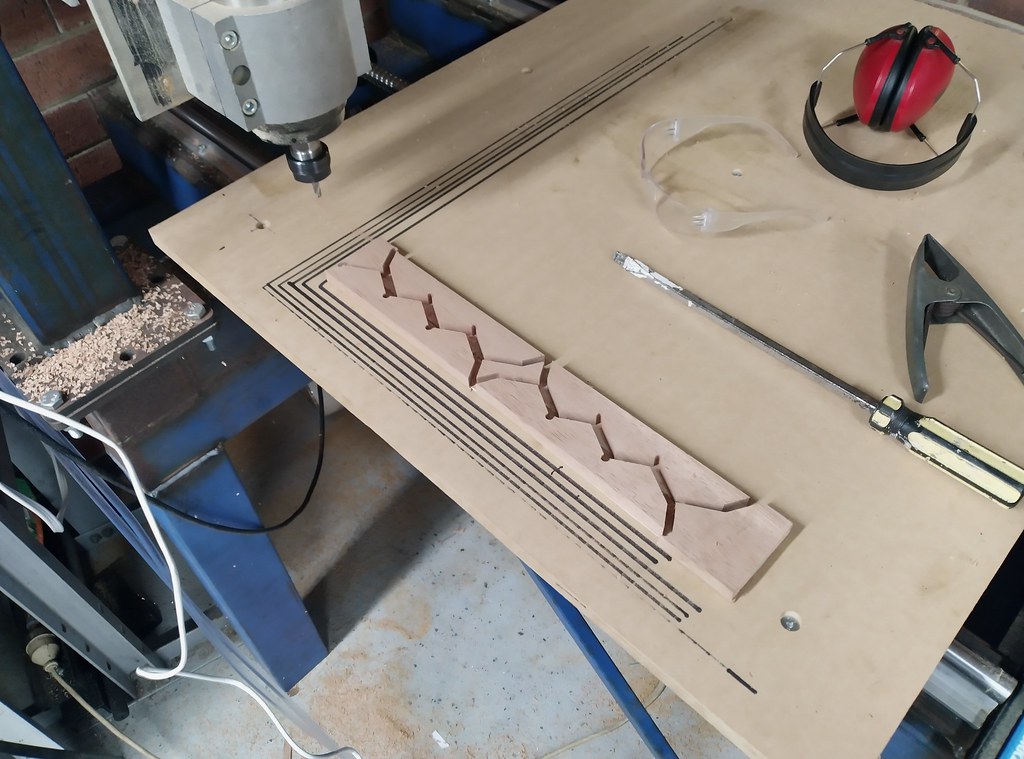
    Then had just enough time to try a quick carving on a scrap piece of MDF. A similar file to my first successful cut on the CNC plasma I made years ago.


    http://www.barberprecision.com.au
    https://www.cnczone.com/forums/diy-cnc-router-table-machines/365922-cnc.html


  5. #65
    Member jones's Avatar
    Join Date
    Oct 2005
    Location
    Australia
    Posts
    73
    Downloads
    0
    Uploads
    0

    Default Re: Welded steel frame router build

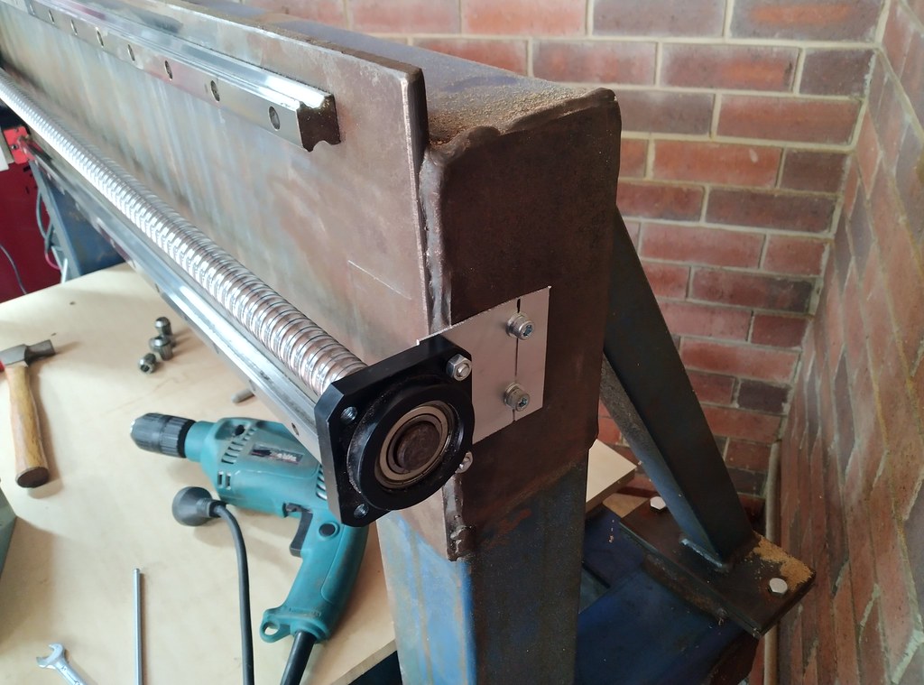
    This weekend I made the outboard ballscrew supports for the X and Y axes.


    They're pretty thin aluminium because their only function is to stop the screw whipping around. I've already tested the machine without any support and it works fine, so these will be perfect.


    Unfortunately this Y axis support I stupidly tightened down with the table positioned at the far end of the machine, so it caused a subtle binding which ruined my next test project about 1/2 way through...


    Until that happened the machine was working flawlessly! I've since adjusted the support and it no longer binds so I may try and run this carving again later on in the week.

    http://www.barberprecision.com.au
    https://www.cnczone.com/forums/diy-cnc-router-table-machines/365922-cnc.html


  6. #66
    Member rudifisk's Avatar
    Join Date
    Jul 2020
    Posts
    2
    Downloads
    0
    Uploads
    0

    Default Re: Welded steel frame router build

    New guy here,
    I have been reading this build with great interest and thank you jones for such a labor of love to document your build. And in no way do I mean to be critical, but one thing jumps out at me. Why did you choose to make the table your moving X axis instead of moving the gantry? Is it because you anticipated the table would have less mass than the gantry?

    Randy


  7. #67
    Member mactec54's Avatar
    Join Date
    Jan 2005
    Location
    USA
    Posts
    15362
    Downloads
    0
    Uploads
    0

    Default Re: Welded steel frame router build

    Quote Originally Posted by jones View Post
    Haha thanks mate, lots of mozzies around my area so the bug zapper is an unfortunately necessity.

    I did a bit more on the CNC over the weekend, I plumbed up the coolant system and mounted the e-chain for all the moving wires


    Got the electrical box pretty far along (yes it's a plastic tub from the local hardware place with a piece of MDF on the back to screw the components to...)


    All axes seem to be moving well and I now have spindle speed control hooked up to the computer. All that's left to do before first cuts is to attach the MDF table to the RHS table frame with a few M6+rivnuts and let 'er rip!
    You have a lot of unsafe wiring; your spindle cable will fail for sure, regular domestic house cable is not suitable for machine wiring

    Is that just 3 wires connected to the Spindle, this is very dangerous if it is only 3 wires connected

    Mactec54


  8. #68
    Member jones's Avatar
    Join Date
    Oct 2005
    Location
    Australia
    Posts
    73
    Downloads
    0
    Uploads
    0

    Default Re: Welded steel frame router build

    Quote Originally Posted by rudifisk View Post
    New guy here,
    I have been reading this build with great interest and thank you jones for such a labor of love to document your build. And in no way do I mean to be critical, but one thing jumps out at me. Why did you choose to make the table your moving X axis instead of moving the gantry? Is it because you anticipated the table would have less mass than the gantry?

    Randy
    Hi Randy, a very reasonable question! Generally having the table set up this way, all else being equal, is much more rigid than having a moving gantry. You also don't have a stack up of the play in the axes. What I mean by this is if the gantry rails have some play, and then the X axis rails on top of that have some play, and then the Z axis rails have some play, by stacking them all on top of each other you compound the issues resulting from such movement. In this configuration only the Z axis is on top of the X, but the Y axis is independent.
    It also allows for a much heavier duty gantry to be used without the penalty of having to move it with huge motors or slow speeds
    The downside is the machine takes up a lot more room for the same size working area.

    Quote Originally Posted by mactec54 View Post
    You have a lot of unsafe wiring; your spindle cable will fail for sure, regular domestic house cable is not suitable for machine wiring

    Is that just 3 wires connected to the Spindle, this is very dangerous if it is only 3 wires connected
    Yes, my replacement spindle cable arrived yesterday which is the proper multi strand flexible cable required.
    Not sure what you mean by 3 wires - the spindle only has 3 wires for the input. Do you mean I should run an extra earth connection to the body of the spindle?

    I don't see how any of the rest of the wiring is unsafe, a bit messy perhaps but it's all rated for the current required and the cables do not move within the cabinet. The body of the machine is earthed as well as every component within the cabinet.

    http://www.barberprecision.com.au
    https://www.cnczone.com/forums/diy-cnc-router-table-machines/365922-cnc.html


  9. #69
    Member mactec54's Avatar
    Join Date
    Jan 2005
    Location
    USA
    Posts
    15362
    Downloads
    0
    Uploads
    0

    Default Re: Welded steel frame router build

    Quote Originally Posted by jones View Post
    Hi Randy, a very reasonable question! Generally having the table set up this way, all else being equal, is much more rigid than having a moving gantry. You also don't have a stack up of the play in the axes. What I mean by this is if the gantry rails have some play, and then the X axis rails on top of that have some play, and then the Z axis rails have some play, by stacking them all on top of each other you compound the issues resulting from such movement. In this configuration only the Z axis is on top of the X, but the Y axis is independent.
    It also allows for a much heavier duty gantry to be used without the penalty of having to move it with huge motors or slow speeds
    The downside is the machine takes up a lot more room for the same size working area.


    Yes, my replacement spindle cable arrived yesterday which is the proper multi strand flexible cable required.
    Not sure what you mean by 3 wires - the spindle only has 3 wires for the input. Do you mean I should run an extra earth connection to the body of the spindle?

    I don't see how any of the rest of the wiring is unsafe, a bit messy perhaps but it's all rated for the current required and the cables do not move within the cabinet. The body of the machine is earthed as well as every component within the cabinet.
    Yes, your spindle should have a 4-pin plug on it, the one you have is for China only if it only has 3 pins, none of what you have would pass an electrical inspection

    You have to change that Plug for a 4 pin then you have to Ground / Earth the 4th pin to the body of the spindle inside the spindle top cap will look like this when you fix it, your cable from the VFD Drive to the Spindle needs to be 4 wire Shielded cable with a flex rating for the job it is doing

    Your so-called cabinet has no Ground / Earth Plane, or Bus so how can you say everything is Earthed, correctly, it is not the way you have it, if the machine frame is Earthed, what is it Earth too.

    Attached Thumbnails Attached Thumbnails Welded steel frame router build-ground-wire-2-jpg  
    Mactec54


  10. #70
    Member jones's Avatar
    Join Date
    Oct 2005
    Location
    Australia
    Posts
    73
    Downloads
    0
    Uploads
    0

    Default Re: Welded steel frame router build

    Quote Originally Posted by mactec54 View Post
    Yes, your spindle should have a 4-pin plug on it, the one you have is for China only if it only has 3 pins, none of what you have would pass an electrical inspection

    You have to change that Plug for a 4 pin then you have to Ground / Earth the 4th pin to the body of the spindle inside the spindle top cap will look like this when you fix it, your cable from the VFD Drive to the Spindle needs to be 4 wire Shielded cable with a flex rating for the job it is doing

    Your so-called cabinet has no Ground / Earth Plane, or Bus so how can you say everything is Earthed, correctly, it is not the way you have it, if the machine frame is Earthed, what is it Earth too.
    I'm not an electrician so I'm sure this is not the proper way to do it, but everything metal is connected to the house earth through the plug. Australian plugs have an earth connection, and this is connected to the machine frame as well as the PSU's and spindle controller. If earthing the spindle is required I'll do that as well

    I appreciate the input and am open to rewiring components, I don't want to get shocked or burn the house down. The spindle cable I ordered is 4 core shielded and flex rated, so should be fine.

    The whole house has earth leakage detectors and circuit breakers on every circuit, so chances of being shocked are low, but better safe than sorry.

    Last edited by jones; 12-19-2022 at 09:28 PM.
    http://www.barberprecision.com.au
    https://www.cnczone.com/forums/diy-cnc-router-table-machines/365922-cnc.html


  11. #71
    Member mactec54's Avatar
    Join Date
    Jan 2005
    Location
    USA
    Posts
    15362
    Downloads
    0
    Uploads
    0

    Default Re: Welded steel frame router build

    Quote Originally Posted by jones View Post
    I'm not an electrician so I'm sure this is not the proper way to do it, but everything metal is connected to the house earth through the plug. Australian plugs have an earth connection, and this is connected to the machine frame as well as the PSU's and spindle controller. If earthing the spindle is required I'll do that as well

    I appreciate the input and am open to rewiring components, I don't want to get shocked or burn the house down. The spindle cable I ordered is 4 core shielded and flex rated, so should be fine.

    The whole house has earth leakage detectors and circuit breakers on every circuit, so chances of being shocked are low, but better safe than sorry.
    Need some photos of how you have everything plugged into you House supply, as it does not sound very good the way you have it as you do not have a Star Ground / Earth connection anywhere, in your machine build, by what you are saying is incorrect, if you have more than (1) connection from your machine to your house power supply then you will have a Ground / Earth loop

    It does not matter what country you live it electrical code requirements are close to the same in every country, Australia being one that is a little more Strick on how things are done

    Mactec54


  12. #72
    Member jones's Avatar
    Join Date
    Oct 2005
    Location
    Australia
    Posts
    73
    Downloads
    0
    Uploads
    0

    Default Re: Welded steel frame router build

    Quote Originally Posted by mactec54 View Post
    Need some photos of how you have everything plugged into you House supply, as it does not sound very good the way you have it as you do not have a Star Ground / Earth connection anywhere, in your machine build, by what you are saying is incorrect, if you have more than (1) connection from your machine to your house power supply then you will have a Ground / Earth loop

    It does not matter what country you live it electrical code requirements are close to the same in every country, Australia being one that is a little more Strick on how things are done
    There is a single threaded ground on the machine attached with a star washer, I just haven't included a picture on the forum because it's not particularly interesting. There is only one 240v connection to the PSU and inverter, and so only 1 house earth connection for the machine and 240v components.

    Anyway, it's sort of a moot point since here in Australia it's illegal to even wire a new plug onto an extension cord unless you're a licenced electrician, so nothing I do can possibly be 'up to code'. I will install a bus bar for the grounds if that's the proper way to do it, though electrically it seems to me no different to how I have it set up at the moment.

    http://www.barberprecision.com.au
    https://www.cnczone.com/forums/diy-cnc-router-table-machines/365922-cnc.html


  13. #73
    Member mactec54's Avatar
    Join Date
    Jan 2005
    Location
    USA
    Posts
    15362
    Downloads
    0
    Uploads
    0

    Default Re: Welded steel frame router build

    Quote Originally Posted by jones View Post
    There is a single threaded ground on the machine attached with a star washer, I just haven't included a picture on the forum because it's not particularly interesting. There is only one 240v connection to the PSU and inverter, and so only 1 house earth connection for the machine and 240v components.

    Anyway, it's sort of a moot point since here in Australia it's illegal to even wire a new plug onto an extension cord unless you're a licenced electrician, so nothing I do can possibly be 'up to code'. I will install a bus bar for the grounds if that's the proper way to do it, though electrically it seems to me no different to how I have it set up at the moment.
    Thats a good thing that you only have one Main Power supply source for your machine.

    Normally you would have a metal plate, this can be aluminum or steel, aluminum is best, that all your components are mounted on, this then is the Ground Plane, you attach a Bus to this, and all your Ground wires then connect to the Bus, (this is your star Point Ground)

    Every component on your machine (moving Axis) would need to have a Ground point for that to work, so that one Ground wire attached to the frame is not going to work very well that is why all components like the Spindle have to have their own Ground / Earth wire all the way back to the Bus, in the Cabinet, this makes it safe some snips for Shield Grounding and Cabinet Grounding The Ground Bus can be as long as you need, The Ground plane metal plate and Bus must be free of paint and have no types of coatings like anodizing Etc.

    Attached Thumbnails Attached Thumbnails Welded steel frame router build-grounding-bus-cabinet-png   Welded steel frame router build-ground-plane-png  
    Mactec54


  14. #74
    Member jones's Avatar
    Join Date
    Oct 2005
    Location
    Australia
    Posts
    73
    Downloads
    0
    Uploads
    0

    Default Re: Welded steel frame router build

    First successful CNC project, it's an open source board game called iso-path, really fun to play


    The tile pieces are bathroom tiles ($12 for all of them ), which dictated the game size, and decorative rocks for playing pieces. I attached self adhesive cork to the tiles which is not super strong, and the tolerances are a bit tight on the board so it can be hard to pick up the tiles sometimes, but it's perfectly playable... Success!

    http://www.barberprecision.com.au
    https://www.cnczone.com/forums/diy-cnc-router-table-machines/365922-cnc.html


  15. #75
    Member mactec54's Avatar
    Join Date
    Jan 2005
    Location
    USA
    Posts
    15362
    Downloads
    0
    Uploads
    0

    Default Re: Welded steel frame router build

    Quote Originally Posted by jones View Post
    First successful CNC project, it's an open source board game called iso-path, really fun to play


    The tile pieces are bathroom tiles ($12 for all of them ), which dictated the game size, and decorative rocks for playing pieces. I attached self adhesive cork to the tiles which is not super strong, and the tolerances are a bit tight on the board so it can be hard to pick up the tiles sometimes, but it's perfectly playable... Success!
    Cool project

    Mactec54


  16. #76
    Member LiamN's Avatar
    Join Date
    Feb 2022
    Posts
    2
    Downloads
    0
    Uploads
    0

    Default Re: Welded steel frame router build

    Quote Originally Posted by jones View Post
    The whole house has earth leakage detectors and circuit breakers on every circuit, so chances of being shocked are low, but better safe than sorry.
    Earthing the spindle housing is a good safety move on a Chinese spindle.

    Without wishing to be alarmist, the earth leakage / residual current breaker does not protect you from the VFD outputs.

    An ELCB / RCD (mostly) works by looking for a difference in live and neutral current on the protected circuit, if these are different that likely means a leakage to earth (that's the mA rating on them). They generally cannot actually measure current in the earth path, for example, you are using a garden tool and standing on the lawn which is the path to earth, the breaker cannot know this.

    A VFD rectifies the mains AC to DC, then makes new three phase AC off the big capacitors inside, the RCD can't measure the three phases of output from the VFD so it can't see a difference and spot a leakage. If your spindle develops a fault such as a frayed wire which sends the housing live, the VFD will just keep supplying from it's local DC power. The RCD can't tell the difference between this and normal operation because the VFD is still drawing power normally. Even if the RCD did spot it and cut the power, there's enough stored energy in the VFD capacitors to give you a fatal shock.

    So, best to consider everything south of the VFD as an old school 230V non-protected circuit that you'd like to be inside an earthed box and not get shocked by.

    HTH


  17. #77
    Member mactec54's Avatar
    Join Date
    Jan 2005
    Location
    USA
    Posts
    15362
    Downloads
    0
    Uploads
    0

    Default Re: Welded steel frame router build

    Quote Originally Posted by LiamN View Post
    Earthing the spindle housing is a good safety move on a Chinese spindle.

    Without wishing to be alarmist, the earth leakage / residual current breaker does not protect you from the VFD outputs.

    An ELCB / RCD (mostly) works by looking for a difference in live and neutral current on the protected circuit, if these are different that likely means a leakage to earth (that's the mA rating on them). They generally cannot actually measure current in the earth path, for example, you are using a garden tool and standing on the lawn which is the path to earth, the breaker cannot know this.

    A VFD rectifies the mains AC to DC, then makes new three phase AC off the big capacitors inside, the RCD can't measure the three phases of output from the VFD so it can't see a difference and spot a leakage. If your spindle develops a fault such as a frayed wire which sends the housing live, the VFD will just keep supplying from it's local DC power. The RCD can't tell the difference between this and normal operation because the VFD is still drawing power normally. Even if the RCD did spot it and cut the power, there's enough stored energy in the VFD capacitors to give you a fatal shock.

    So, best to consider everything south of the VFD as an old school 230V non-protected circuit that you'd like to be inside an earthed box and not get shocked by.

    HTH
    It is not only for Safety; the Spindle Rotor Voltage has to have somewhere to go also which its normal path is to Earth (Ground)

    Mactec54


  18. #78
    Member mactec54's Avatar
    Join Date
    Jan 2005
    Location
    USA
    Posts
    15362
    Downloads
    0
    Uploads
    0

    Default Re: Welded steel frame router build

    Here is what happens in an Ac 3ph motor when power by a VFD Drive the higher the frequency / speed the worse it gets from this it shows how important it is to have correct Grounding / Earth in place

    Attached Thumbnails Attached Thumbnails Welded steel frame router build-ac-motor-shaft-current-voltage-png  
    Mactec54


  19. #79
    Member jones's Avatar
    Join Date
    Oct 2005
    Location
    Australia
    Posts
    73
    Downloads
    0
    Uploads
    0

    Default Re: Welded steel frame router build

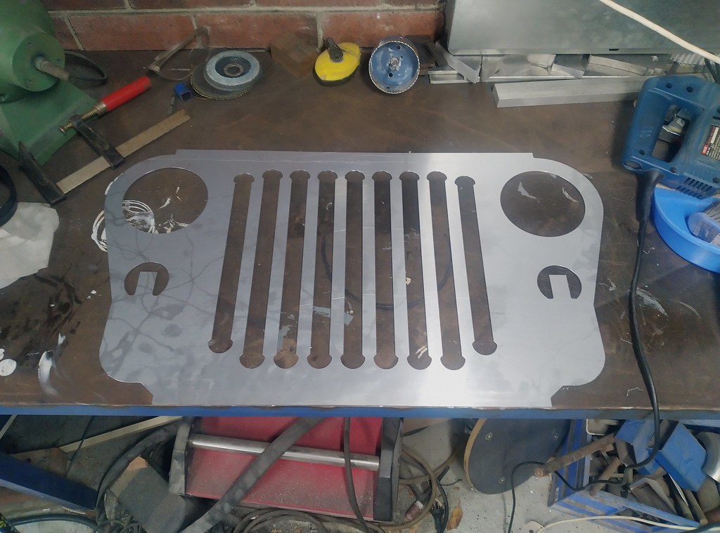
    Cut my first aluminium component with the router this weekend:


    It's a grill for my Ford/Jeep/Toyota hot rod build


    6mm single flute carbide bit, WD40 as lubricant, 11,000 rpm spindle speed, 1mm D.O.C, and 1000mm/min feed. The machine was fine with these specs but I am excited to see what it can do after I machine new X and Z plates from 30mm material for extra rigidity.

    Once the router has proven itself useful I also want to upgrade the Y axis table to profile linear rails like the X and Z axes, then I'll call it mechanically finished.

    http://www.barberprecision.com.au
    https://www.cnczone.com/forums/diy-cnc-router-table-machines/365922-cnc.html


  20. #80
    Member jones's Avatar
    Join Date
    Oct 2005
    Location
    Australia
    Posts
    73
    Downloads
    0
    Uploads
    0

    Default Re: Welded steel frame router build

    Minor update: I've added a bus bar for all the earth connection points, changed the spindle wiring to proper flexible CNC rated cable, earthed the spindle, earthed the machine frame, and tidied up the wiring in the cabinet.

    I've also added holes to mount my milling vice for cutting smaller components.


    Items still remaining:
    1. Dust extraction - I have the extractor unit but need to make a dust boot and run the piping
    2. Coolant/water tank for the spindle
    3. Z axis height setter
    4. Limit switches... still on the fence as to whether I really need these, I've never been in a position where it's tried to go off the end of the travel.
    5. Cooling fan for the enclosure
    6. Paint

    Then the upgrade path:
    1. 30mm thick Z axis plate
    2. 30mm thick X axis plate
    3. Upgrade Y axis/table to profile rails
    4. Aluminium table with tapped mounting holes all over it

    I'm not sure how far through all of these I'll get before I call it "good enough" but it's good to have a list of things to do when I'm bored and have time.

    http://www.barberprecision.com.au
    https://www.cnczone.com/forums/diy-cnc-router-table-machines/365922-cnc.html


Page 4 of 5 FirstFirst 12345 LastLast

Tags for this Thread

Posting Permissions

  • You may not post new threads
  • You may not post replies
  • You may not post attachments
  • You may not edit your posts
  •  


About CNCzone.com

    We are the largest and most active discussion forum for manufacturing industry. The site is 100% free to join and use, so join today!

Follow us on


Our Brands

Welded steel frame router build

Welded steel frame router build