


 Reply with Quote
Are the balls glued to the carrier?


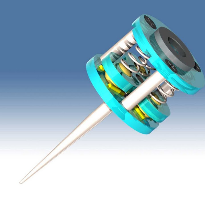
Inspired by some touch probes described in other threads I built one today from 1/2" ball bearings, some pins, spring and 5mm Acrylic. Works pretty neat, and I though I might just as well post it here. Now I just got to find out what to use it for
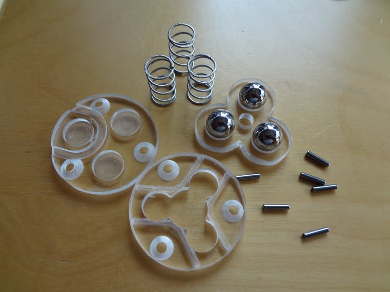
Materials:
Glued together:
Assembled:
Probing a coin with 8/1000" grid:
Resulting .stl file. The mint pattern depth of this coin is only 0.15 mm or 6/1000 so I guess I can not expect more accuracy:
In operation. No this is no woodpecker, this is the Z-axis stepper:
http://www.youtube.com/watch?feature...&v=LvSeUWyTnCU
Similar Threads:
Are the balls glued to the carrier?
Yes. The balls, pins, cable and stylus are glued in with medium viscosity super glue. Could have used epoxy just as well. I did roughen the metal glue surfaces with sand paper.Originally Posted by Dragonfly

Nice simple design.
Do you have drawings available? I could see whipping one up myself.
Thanks
-Geoff
What do you need? Solid model, .DWG, Vectric V-Carve or G-Code?
Solid model and DWG as a fallback would be awesome if at all possible!
sounds like impact engraving
JTCUSTOMS
"It is only when they go wrong that machines remind you how powerful they are."
Clive James
I too would love to make one of these. Not for probing but more as a stationary touchplate for tool change. Vector/vcarve would be the file I would like to have
Heck, maybe I'll make one for probing too.
Nice work man!
I will make a model/drawing file package tonight. In the meantime here is a BOM of the small parts with McMaster-Carr numbers. I had the steel balls already and I am not sure if there is a source for them where you can buy less than 100. Maybe you can find a suitable ball bearing or buy metric 12mm with a 10-pack. Smaller balls would work as well if the design is modified but are not as easy to assemble.
The plates are 0.2" Plexiglass/acrylic, but that is quite brittle. Lexan, PVC or Garolite may be easier to do. The needle bearing was cracked in a vise to extract the steel pins and the drill rod tapered in a drill press with an angle grinder to achieve the probing tip (water hardened the tip after grinding).
I will actually make another probe and gold plate the steel balls and pins to avoid long term corrosion and for more reliable contact. If that is not available, the contact surfaces should be at least coated with silicon grease (automotive electrical grease) or similar. Minimum recommended current is 5-10 mA (e.g. 1kOhm pull-up/down at 5Volts) through the probe contacts when closed to facilitate proper switch function.
Last edited by JerryBurks; 06-05-2012 at 04:13 PM.
Here are the files
It contains .stp, .sat, .dwg, .pdf, .crv and 3-part G-code versions. I hope some of them will work.
Last edited by JerryBurks; 06-05-2012 at 11:28 PM.
nice work!
Nice design Jerry! Re-centering of the balls after each probe movement looks reliable too, which is better than some designs.
Using hardened pins would be better (as I'm sure you know based on the nice hardened needle bearings in your top photo) but it's not that easy to connect them electrically. Instead of connecting the wires to the six pins you could make 3 triangular metal (brass?) clamps which clamp the 6 hardened pins in place. Each clamp would be like a tirangle with a hole in the middle for the clamping screw or pillar. Then you could solder the wires to two of the clamps. Just a thought.
Thanks Roman, that would be an idea but the space is very limited for such additional hardware and I don't know how to make it simple and sturdy.
You are right about the contacts. For my first assembly I cheated and used the thin walled gold plated steel barrels of pogo pins (the spring loaded electronic test probes) but these are not as resilient as solid hardened steel ones. Right now I am working on a second model since I got the steel pins and balls gold plated (thanks to my wife's jewelry hobby), see below. I might actually be able to solder wires directly to the gold plated pins but will rather go the route of silver filled conductive epoxy for the wire connections (like the stuff used for rear window heater repair).
Last edited by JerryBurks; 06-07-2012 at 12:03 PM.
Nice job..... I have been wanting to mess with a probe system for a couple years. I think your post may just get me started.
Thanks,
Robert
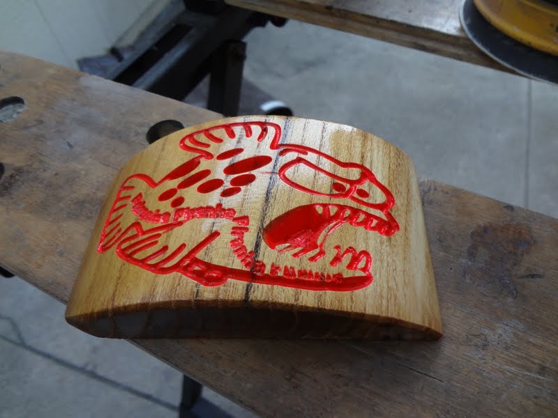
I tried another use for the touch probe today, to sample an uneven surface and warp the G-code with the resulting data.
I used this Vectric V-carve pattern to generate the G-code:
Then I sampled the curved surface of my blank (an odd chunk of mulberry wood), applied the warp to the G-code (sample and warp is a feature of the Planet-CNC machine controller) and carved the pattern with a 60 degree bit:
PiranhaVcarve.avi - YouTube
Quite nice result. Not perfect because I lost the zero position sometimes due to my mistake but I may try it to carve signs with curved surfaces.
Last edited by JerryBurks; 06-10-2012 at 02:30 AM.
seems that there is a lot of pressure applied on the probe...
some years ago I tried something similar ...
Why reach for speed, when you could have precision instead!!!
Yes, the pressure is more than I like. It takes about 1.5 pounds of force to lift the balls off the pins vertically and 0.5 pound horizontally. I tried reducing the spring force but the return becomes unreliable at some point. Since the tip is rather sharp (about 0.5mm radius) I can only scan materials like metal, wood or hard plastic. For softer materials I would have to use a larger diameter ball tip and/or use softer springs.
But since I do only wood and metal I think I leave it the way it is.
If the impression of high forces comes from the knock sound when the tip hits the surface, that is actually the stepper coming to a hard stop.
Really cool....Very very clever idea!
That gold plating is a great idea, I'd like to know how it works out. Gold makes a great contact material (and you may be able to reduce spring pressure) provided it doesn't get wear issues.
Hi.
I think this gives another approch to designing touch probes. I think it is very simple, not so many parts. And with few parts easy to mashine. But I have some questions.
1. Have You made any accurcy testing/repeterability?
2. How do You adjust runout on the probtip.
Best regards to all of You from John Eriksson in Sweden