

 Reply with Quote
Sturdy looking router, thats for sure
Looks like you will have plenty I/O with that lot, suppose I would have needed a few more modules if I hadn't used the PLC for the tool changer.
Looking forward to seeing your progress.
Hood


While this is going to be somewhat of a project type thread, I think it may serve best being here in the CSMIO forum since it will pretty much encompass specifically how these controllers can be used in a retrofit. I don't plan to cover much in terms of the machine itself, other than how the CSMIO is used to accomplish various tasks needed in the machine. Hopefully, others will agree that this is a good place for this topic.
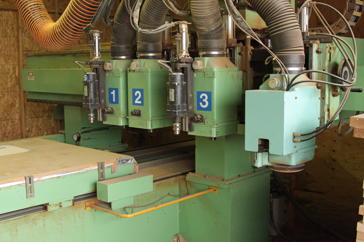
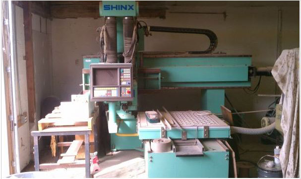
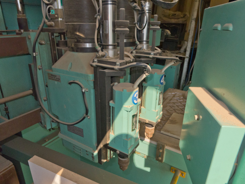
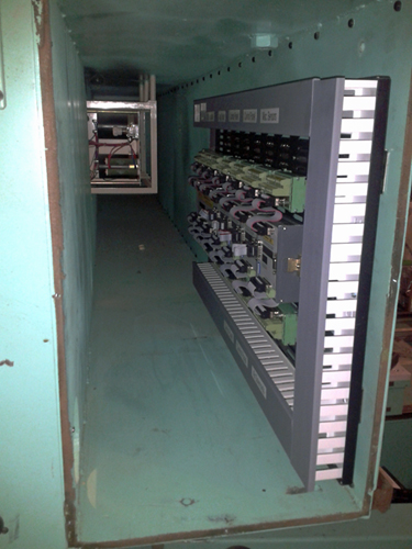
First, this is not my first commercial CNC router and I've had experience with several over the years. I bought an SCM Routomat sometime around 2003 and had some exposure to them prior to that as well, all the way back into the early 90's when working at Gibson Guitar in Bozeman, MT. If I remember right, they were using a Fadal at the time, so not a CNC router so much as a machining center. Never the less, I found the machine and all the hand coding that was done to be fascinating. I sold my woodshop a while back, just before the market tanked, and have taken some time off from woodworking since then, spending it with my kids while they are still young. Over the last year, I started considering getting back into the business and focus solely on CNC work. To get started, I wanted a machine that was industrial, but also would fit in my 24x24 ft garage so I could start out working at home and see where it goes this time around. I found a 1991 Shinx CNC router with a 4ft by 4ft work area, twin router heads, each with a piggy back drill, that can be spaced at various OCs for multi-part simultaneous cutting. The price was right and the terms even better, so I went for it. I think I got it for less than it's scrap price, though it does weigh about 8000lbs (used a 15,000 lb lift to get it in the garage!). It takes up about 12 feet across the gantry including the motor, and about 10 feet front to back. It just fit under my 8 ft ceilings by about half an inch, but only after I removed the pneumatic dust collection rams. Some photos of the machine:
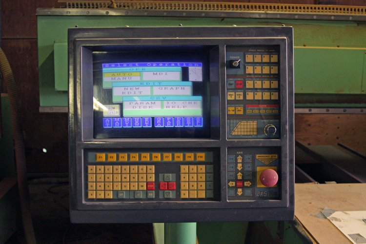
The bad news was that the controller was non-operational (the price reflected this, so not a deal breaker). After checking it over, I found the PC, which was not a normal off the shelf variety, seemed to be having trouble reading the system disc. The entire CNC ran off of a 3 1/2 inch floppy, and there was no hard drive in the unit, just 640K of RAM. I found a guy that was very good with vintage computers, and he basically just laughed when I asked if it could be repaired. He did confirm that the problem was in the PC itself, rather than the drive, or any other easily replace peripheral. At that point, it seemed like a waste of time to continue trying to do a quick fix, so I started researching the latest crop of controllers.
When I had last owned a machine, the only things available that could run an industrial machine reliably and integrate with the analog servos were either very expensive, or very hard to figure out how to configure properly. Centroid controllers were at the top of my list then, so that's where I started looking. I don't remember Mach being a serious alternative for large and complicated machines at the time, so I had pretty much dismissed it. I have to say that I'm surprised what has transpired in the last 6 years or so. I was surprised to find that there are multiple candidates for this retrofit and had given consideration to Vital Systems dspMC/IP and Dynomotion KFLOP, both of which could use the servos the machine already has. I won't go into specifics about why I chose CS Labs over those products, but the main reason is that I like the modular expandability and the overall design of how the product lays out. I think it has a leg up on anything right now in terms of providing a clean installation layout and has all the features that I need. Mainly, I needed a ton of I/O connections as I plan to maintain the original control panel with LED indicators; and I needed analog control of my servos with a closed loop system. The CSMIO IP-A covers those needs at a price that is extremely competitive, particularly once you compare like numbers of I/Os.
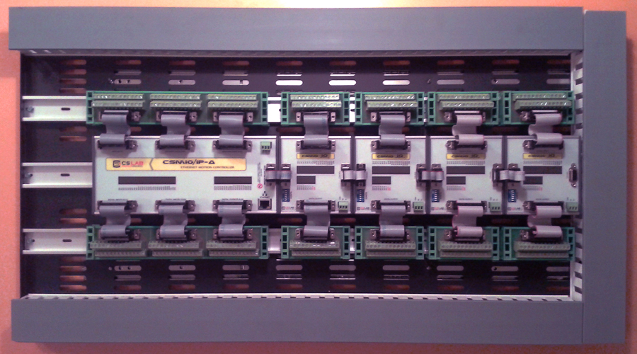
I ordered and received my controller and I/O modules in under a week, all the way from Poland to Seattle. Right away, I started working on figuring out how to integrate the new controller with my machine and had a great deal of good fortune. I bought a server rack vent panel, which is made of some reasonably heavy stamped steel with half inch sides bent from the face to make a rigid panel. This was $10 at the local PC recycling shop, along with another $10 for a pair of full extension server drawer slides. This combination appeared to be enough to get most of the panel out of the machine for servicing/installing, while allowing it to slide completely into the machine during use. I had some spare Panduit channels laying around, so all I needed was some covers (which I bought at the local industrial supply) and some DIN rail. Here's the finished assembly, though the controller and I/O modules are in a somewhat random position at this point:
After drilling and tapping some 10-24 holes for mounting the server slides, this is the resulting installation to this point:
The original controller was located in the same location, and since there is so much room in the gantry, it seemed it would be a shame to waste it. Plus, there is a fan at the other end of the gantry tunnel, and a filtered cover that will go over the open end which I'll eventually make into a operating door. The panel is about 17.5" tall and 32" long, so that may give some scale to the photos. The servo power supply is about two and a half feet farther into the tunnel than the end of the panel, but since the original controller didn't have any problems, I'm not expecting that it will be an issue now either. The gantry is somewhat of an "H" beam, though welded that way, with a closed front face. It's made of just under 1/2" plate steel, and there is already a 3-4" hole cute through the center plate for wiring (thank God, I would not have wanted to deal with drilling a hole through that!). I plan to run wire from the top inner most corner around the outside and out the lower inner corner of the Panduit channel. The wiring will run through the hole, which is near the opening, and when you pull the panel out it should have slack built in to allow the motion.
Hopefully I'll have some more progress by next weekend, and some better quality photos.
Similar Threads:
Last edited by mmoe; 06-01-2013 at 04:12 AM. Reason: typo
Sturdy looking router, thats for sure
Looks like you will have plenty I/O with that lot, suppose I would have needed a few more modules if I hadn't used the PLC for the tool changer.
Looking forward to seeing your progress.
Hood
I kinda regret not buying the MPG module as well. I have a space just waiting for one there.
I would have reused the PLC if I could have figured out what it was doing, but it was not entirely clear without having seen it operate. A new PLC would cost just as much as the I/O, and since I don't have a lot of PLC programming experience, it will be just as easy for me to do the job with VB and Brains in Mach.
I'll be using most of the I/Os for the control panel, which I have to re-solder into a matrix type panel. It's currently set up with a proprietary chip more like a keyboard, but there is no documentation on it. The jog panel is set up with independent switches for X, Y, Z, A, B, C, Release (from limit switch), and two empty buttons. I could rewire it into a matrix to save some I/Os, but the I/O modules are so economical that I value my time a bit more. In a matrix, it would take up eight inputs, and without it still only takes up 15 inputs. For those unfamiliar with the CSMIO controllers, the I/Os on the main control module need to be left for "fast" I/O functions, such as limit switches. Because of this, I'm working my wiring scheme clockwise starting with the low level inputs at the first I/O module, and ending with the fast inputs at the bottom of the main control module. I also plan to add one tool-changing head to the machine in the future in place of one of the current heads (probably head 2). I've got a nice Italian made 10hp ATC spindle just laying around.
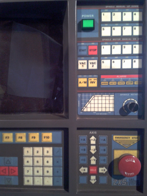
Here's the control panel as it currently is:
I won't be able to use the keyboard as it's yet another proprietary configuration and I would rather buy a similar keyboard in USB format than try to monkey around with it. I do plan to keep the Function buttons, so I'll have to machine that portion off the keyboard and rewire it as well.
A couple years ago I almost bought a machine that was a longer bed version of this one. The owner was asking $3500, but needed to move it and it weighed nearly double of what mine does due to additional heads and the larger table/frame. Estimates from the manufacturer were around 15,000 lbs, so moving it was going to be expensive. I offered $1500, but he did not take the offer. Apparently, he put it on Ebay right after that (I was not aware), and someone from Texas bought it for $999. At any rate, the machines are nearly identical, so I plan to increase the table capacity to 4x8ft as the other machine was. I do REALLY regret that I did not purchase the first one, these are really well built machines. Here's a link to a thread by the guy who bought the other machine, followed by some of my own photos of the same machine:
http://www.cnczone.com/forums/joes_c...99_router.html
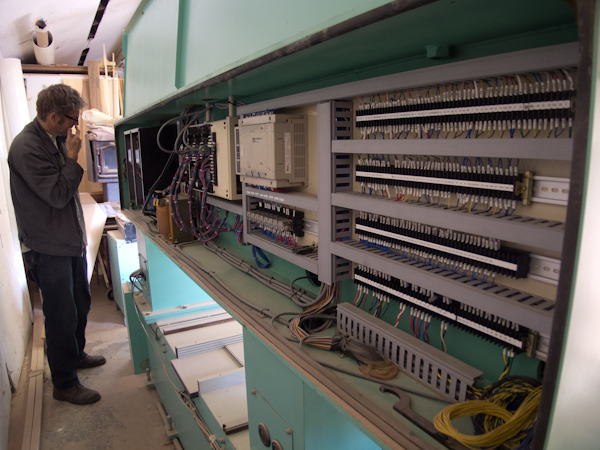
Short update today. I originally hoped to reuse much of the wiring as is without having to redesign too much of it. I started out by tracing all the wires end to end to figure out what they were for, since I don't have a wiring diagram for the machine. I then labeled everything that could be identified and started contemplating how to fit the CSMIO into the picture. What became very apparent was that the wiring was not done in a way that would easily lend itself to the new control, mostly due to the mix of PLC a completely different power supply system than what would be needed. While it was good to figure out how the machine was currently configured, it turns out that I ended up just completely removing the wiring and starting from scratch.
I was able to reorganize the servo wires without a whole lot of fuss, and put all the servo wiring both for the servos and encoders on one long set of terminals. I then added a 24 volt power supply, the original being only a 15 volt system. After reading through the CS Labs manuals for the I/O and the IP-A/IP-S, I realized that I would need a second 24 volt power supply. It doesn't really explicitly say that you need separate power supplies, but the diagrams showing the power system for the I/Os clearly depict the power coming from a different source than the power supply used for the controller and modules themselves. After some looking, I bought a 50 watt IDEC power supply similar to the 100 watt unit to power the controller/modules. The controller and modules will use about 15 watts in total, so they will be very comfortable on the 50 watt supply. I estimate that the I/O system will probably also only use around 25 watts at any point in time, given that the outputs only allow for 250ma of current each and I have a total of 36 outputs. In theory, if every one of them were active and at maximum current (which I hope to avoid and plan to keep current manageable), they could use a total of 216 watts or so. I know my LED outputs will be closer to half the full current rating, and hope to be around 200ma max for the relays. In that case, they would use considerably less than 216 watts and I can't think of a situation where all 36 will be active at the same time, so 100 watts of supply should be more than enough. It is something I'll be keeping track of as I go, just to be sure that I'm not short on power.
Next, I need to redesign how the main power relay works along with the e-stop system and start looking at how I want to wire the rest of the relays for motor contactors, etc.
The manual describes situations where 2 supplies may be preferable, I just use one but its a big supply and very stable and I have no problems. Anyway heres what the manual recommends.
"If you use in the system such inductive loads as electromagnets, solenoids,
electromagnetic clutches – it’s recommended to use a separate 24V power supply
for the above receivers and separate for CSMIO / IP-S. "
Hood
I was not certain whether they meant significant loads or if low current relays would be excluded; so errored on the side of caution (and 100 watts may have been close to underpowered). I was also not sure if the isolated outputs would be compromised by use of the same power supply as I'm admittedly not well educated on the specifics of galvanic or opto isolation. I understand some basics, but don't know what is considered kosher and what is not when it comes to wiring.
There is a difference between the CSMIO manual and the current Plug-In Installation proceedure!
"The plug-in installation comes down to copying a single file." (as stated in the manual).
The manual states that the CSMIO*****.dll file needed for the plug-in should be copied and pasted from the supplied software, with the destination being the /Mach3/PlugIns. I could not find this file to copy/paste anywhere on my CD, and the only downloads I found on the website were (and are) the firmware updates. What was not clear, is that all you have to do now is install the firmware software, and it automatically installs the CSMIO****.dll file in the appropriate Mach3 plug-in directory. As the manual cautions, be sure that you have the matching .dll file to go with the firmware. In my case, the hardware came with firmware that was older than the firmware/dll supplied on the CD. The firmware was also older than the latest firmware available for download, so check for updates.
I was able to wire up the first I/O module to the jog panel buttons from the original controller. After only about 5 minutes, the entire jog panel was set up for all it's functions. It's really impressive how easily configured Mach 3 is, especially considering that the it will integrate seamlessly with a button panel from 20 years ago. The CS Labs plug-in is also quite easy to work with. From the plug-in window, you can click on the modules individually which brings up a panel showing the I/O activity for verifying that everything is working as it should. The plug-in also shows what the port number of each device is, and the activity panel has the pin numbers shown. When adding I/O modules, you have to set dip switches to indicate which number it is in the string of devices. All of that is very well covered in the manual and I've been able to set up all 16 inputs from the instructions with no issues. The outputs are also easily configured and have clear instructions, though I've only set up test LEDs (with resistors) at this point. I doubt that there will be any difference between an LED and a relay in practice, and the relay takes less current to operate.
I'm planning to fool around with some brains this evening and see if I can get some basic functionality started, such as turning and LED on which stays on after a momentary switch input, then turning it back off from another momentary switch input. This would be that same basic brain needed to operate the up/down motion of each router head to put it in or out of the machining position. I've decided to remove the two piggy back drills and eliminate them from the system since I've found that they only operate with about a 2 1/2 inch up/down motion when in or out of use, respectively. The problem, as I see it, is that the drill bit will not extend very much further down than the router bit, or, in the case that it does, won't retract very far up from the end of the router bit. There seems a high likelihood that in materials greater than 3/4 inch thick, there could be tool collisions that aren't intended. It's not quite the same thing as having four different heads on completely separate pneumatic positioning tracks, where they move closer to 8 inches up/down, which keeps them completely out of the way. I'll be adding the toolchanger head in the not-too-distant future, which will be far more useful than the piggy back drills and can do the same things. I may add one of the drills in the future, on it's own track next to one of the two main heads, but it will only be done if I can get it to cover the entire table left to right.
So far, I'm finding that brains are not very useful for toggling outputs on/off. Perhaps I'm just not getting it, but at this point the only way I'm getting it to work is with scripting. Brains seem to be mostly useful for passing signals, but not so much for turning them on or off independent of other signals being on sustainably. For example, if you hold a momentary switch down, it will pass the signal for as long as you do. As soon as the signal is let off, it will turn off in the brain as well. I can see brains as useful for sorting out a button matrix, or monitoring outputs to send additional outputs (for example, output 1 is active, so send signal to output 10 to light LED indicator), but so far do not see this functionality as useful for the purpose of operating relays. It would be just as easy to use the relay itself to light an LED indicator mechanically, but a little more convenient to be able to change them around after wiring in the event it's needed by using brains instead.
One thing I'm trying to figure out is how to access the remainder of inputs/outputs beyond those I've assigned to "input 1", "output 1" etc. There are about 30 user inputs and outputs for unspecified purposes, but I really need about double that. I suspect that a the scripts can contain a port/pin variable rather than using these predescribed inputs/outputs, but haven't yet learned or figured out the formatting. Until I do, I've got quite a lot of connections that are idle.
I have set up the encoders, and when I hand turn the 20mm ball screw (and motor) one approx. rotation, the DRO reads out 20mm, so all seems good. I've also added the E-stop and limit switches. There is quite a lot of work to do designing the relay system and power supply system. The original power supplies were all different voltages from what I need now, and it's been difficult to discern what the purpose of some of the power system is (making a neutral 0volt from 3phase for a single phase 100v?).
I have used the macropump for non-standard I/O on the Chiron as I am invoking some scripts when they are seen. You do not have to set anything in Ports and Pins if doing that, all you do is use the modbus address for the input/output as detailed in the extra I/O module manual. You can also do that in a Brain but latching may be problematic although I have done it in the past on other machines, would have to look to see how I achieved it.
Hood
Thanks Hood!
The information at the end of the I/O Module manual appears to be exactly what I need. I can't believe I didn't see it previously as I've printed all the manuals out an have even printed extra pages of the Inputs and Outputs pin-outs for documenting what I've connected where.
Just as I've stated earlier, either in this thread or elsewhere, the CS Labs documentation is really quite good and in most cases the only reason I can't figure something out is that I have ignored it or missed it all together in the manuals!
While I think I understand how to get the inputs and outputs through Modbus in brains, the main problem of latching the signals still seems to be in place. It just isn't that much trouble to write scripts to do the same thing. While I understand brains are supposed to be much faster, I'm not noticing any delay, so I think I can live with the speed it runs at from scripts.
Also, the more I get to know the CSMIO IP-A controller, the more I like it. And that's saying a lot as I liked it from the start.
Brains and macropump will just run at Mach3's update rate which is 10Hz, Mach 4 will be faster.
That being said the macropump will slow down the more you have in it where brains will not. The problem with large brains however is the difficulty in viewing them. If that is the case then it is much better to make multiple smaller brains as they will all run at the same speed and you will be able to view them more easily.
Hood
Hood,
It seems you are generally in the know about what CS Labs is up to in that you have mentioned firmware updates in advance in the past. Have you heard anything about the current IP-A working with Mach 4 in the future? From what little I've seen on Youtube, Mach 4 does look like a very substantial improvement over Mach 3. Once the machine is running, I don't think I'll have any choice but to buy Mach 3 if Mach 4 isn't out. I stand to loose a lot more money by not having the machine running than the loss of $150 for the software, so it's kind of a no-brainer. I suppose that even if Mach 4 is out by then, I'll have to use Mach 3 until I figure Mach 4 out anyways, so I suppose I'll be buying both either way (assuming the IP-A will work with Mach 4). It seems like the advantage of hardware such as the IP-A is that a firmware update will probably be all that's needed, correct?
I know Brian has sent info to Andrew regarding Mach4 and what it expects for a plugin.
Last time I talked to Wojtek there was mention that Andrew would be starting to do a Mach4 plugin shortly, whether it has been started yet or not I have no idea.
Hood
I've been having issues with relays today. The original relays are old and some have failed or are at least intermittent, so I bought some new ones to replace them with. The originals, which the CSMIO IP-A has no problem operating (at least those that are actually working) are Matsu****a HC4-DC24V, which are 24v coil that measures at approx. 640 ohms and operates at approx. 40-50ma. The new relays I bought are IDEC RU4S-D-D24 and uses around 40ma as well. The problem seems to be that the coil is different some how. When I measure it the same way I measure the original, it measures at about the same 640 ohms. The specifications, however, show it at less coil resistance, with around 150 ohms, which I think would be too little. I don't understand, however, how it could measure at 640 ohms if it is in fact less.
The result is that the outputs show an overload fault. Given that the coil should operate at well under the rated output power and that the older similar relays work perfectly, I have to wonder if somehow the coil does not behave like a normal 640 ohm load. Part of the load may be an indicator, which may be the issue, so I'm thinking that if the specifications say the coil is a 150 ohm load then it may be too little. I guess I'm just a bit surprised because it seems to measure out properly at the contacts (640 ohms, not the 150 specified). It appears that I can get an equivalent to the originals, which I know will work, so that may be the best solution. For what it's worth, the current equivalent that I know to be operable is now made by Panasonic under the same part number as the Matsu****a.
I'm going to return the IDEC relays and see if they have a better match tomorrow. If so, I'll update which models work and which don't. I do suspect that the LED indicator/diode circuit may be causing the problems, so hopefully they will have one without the indicator. Otherwise, the Panasonics are all mail order for me.
Last edited by mmoe; 06-19-2013 at 10:48 PM.
Apparently, you can't say Matsu****a in the forums, so you'll all have to be cleaver enough to fill in the blanks.
As I suspected, the diode indicator version of the ITEC relays does not agree with the controller. I picked up a non-diode relay today, which still has an LED indicator, and it works perfectly well. The part number for the relays that do work well are:
IDEC - RU2S-D24 (2 pole relay)
IDEC - RU4S-D24 (4 pole relay)
Last edited by mmoe; 06-19-2013 at 10:48 PM.
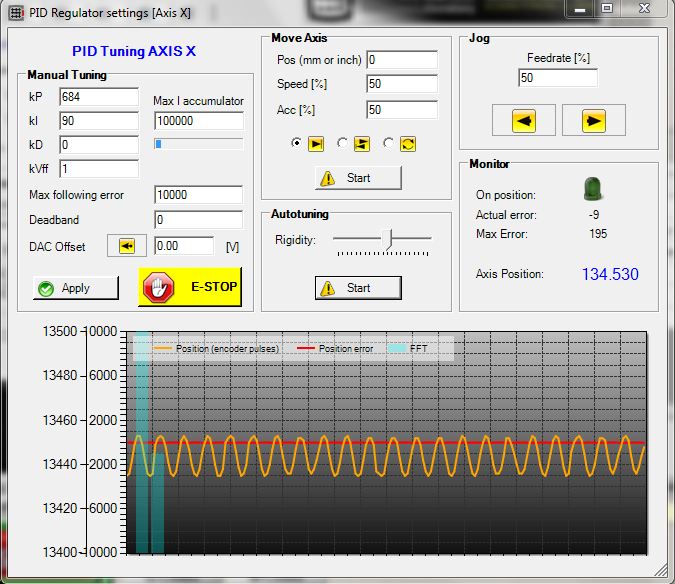
Just starting to learn a bit about PID tuning with CSMIO. I think that I'll have to fine tune the servo drives a bit more first, as they seem to be out of the limits of what the CSMIO plug-in can adjust.
Got all three axis working, though still not tuned. As long as I keep it at 1000mm/min or less, it's smooth enough to test some functionality. I have to say that the home on index with the IP-A is absolutely fantastic. My anecdotal experience is that the axis all appear to end up in precisely the same place every time (as they should in theory). While I haven't measured, I have watched the encoder counts in the CSMIO plugin which shows that in every case they go back to the exact same encoder count. I thought they would all three be zero, but while the "X" and "Z" axis are both reading that they return to the first zero after coming off the home switch, the "Y" axis goes to a number like 435 (off the top of my head). It always lands on the same number, but I found it curious that it wasn't zero. I did not verify that the wires from the encoder are hooked up at the the motor end properly, and went with what they were labeled as in the electrical cabinet. I would imagine that if they weren't properly hooked up, the encoder would not be working properly, but I'll verify tomorrow that the wires are correct anyways.
I've taken some photos of the project, so hopefully I can give a bit of visual information about how the CSMIO IP-A is installed. I started out with my nice label maker, but ran out of label tape, so you'll have to bear with me as I've just used hockey tape and a Sharpie to label things for now.
A big part of what I was trying to decide as I was starting out was how to install everything in a way that I could remember 5 years from now. I wanted it to be reasonably intuitive to figure out which wires go where without a whole lot of guess work. The machines I've owned always use a numbering system for the connections that seem to be mostly randomly assigned, though groups of similar wires get numbers close together. All in all, if a machine has several hundred runs of wire, there will be numbers ranging from 0-500 at various terminal strips through the machine, and then at the start and termination of the wire. While that's all great if you have a wiring schematic, it does little to help a person discern where the wire originated or terminates when looking at a terminal strip in the middle of the circuit. So my solution would have to be something where you can look at the terminal strips in the middle and still identify the origin or, in some cases, termination.
After some initial attempts at labeling the functions of each wire at each terminal, it became obvious that this was not useful information. The cool thing about Mach is that you can see what the function of signals is from within the software, so long as you know the port/pin. At that point, I decided to label everything in that manner; by port and pin numbers. In fact, the pin number system is the physical pin in order from start to end (skipping power supply pins, non-signal pins), not the actual pin, so there is some ambiguity there for someone who doesn't know the system I implemented. However, for my own purposes the system is quite easy to read and understand. For a given port at a I/O Module, for example, I have labeled the inputs 1 through 16 and the outputs 1 through 8 (there are 16 inputs and 8 outputs) according to their position in the CS Labs manual supplied with the device (though they start at 0 instead of 1 in the manual). I'm sure that sounds a bit confusing, as it won't actually match the numbers in Mach, but rest assured that it makes sense to the one person it needs to.
Here's some photos of the wiring as it is currently. I have a ton of inputs/outputs to run still, but most of which are add ons after the machine is up and running. I am going to be remaking the button panel circuit board to adapt it to a matrix system, so that will require the use of the machine itself. I also plan to add a tool changer, but that will also require making some parts with the machine as well. The spindle is still not hooked up, so some outputs/inputs will be used there. About 3/4 of the empty outputs will be used for LED indicators of different functions at the control panel, and most of the remaining slow inputs will be used for the control panel buttons (I/O module inputs are not to be used for fast input functions, like E-Stop, but are still pretty fast).
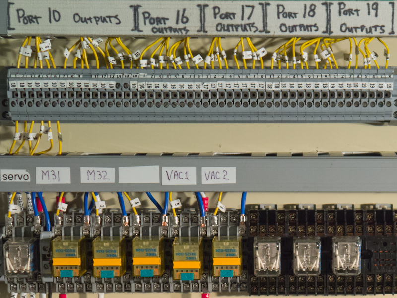
Below is the layout of digital ports in the CSMIO and I/O module system. The analog ports are the unlabeled top portion. The numbers represent the port number, not the number of I/Os. For the IP-A controller, there are 24 built in digital inputs and 16 digital outputs. For each I/O module, there are 16 digital inputs and 8 digital outputs. The digital outputs require a 24v power supply for every 4 outputs as a group. On the I/O modules, you can see this by noting that the yellow wires are the actual outputs and the power/common is supplied by the red and green wires. All 8 outputs are wired in for the I/Os, so the empty spaces are just that, empty and unused:
Below is my labeling system as it relates to the ports shown in the last image. I can look at any wire and know which module and pin the wire goes to on the controller. From that, I can also know which port/pin the given input or output has in Mach. As you'll notice, I ran out of 10s (need to pick up some more):
There are a couple of custom M functions run by the relays labeled M31 and M32, which I show later when I have some photos of the machine in operation. They can be canceled with M35 and M36 respective, or both by M30 or M5 depending on if I want the spindles to stop or not. The relay to the far left closes the servo loop, which allows the servos to operate. It also activates the clutch on the Z axis which is a 90vDC brake coil. An E-Stop disconnects the 24volt supply to the relay in addition to triggering an E-stop in Mach, so even if Mach failed to disable the servos, an E-stop will turn them off regardless. The Vac1 relay operates the 5 hp vacuum pump, while Vac 2 will operate an additional pump in the future. They are operated by M21 and M22, with M25 and M26 cancelling each respectively. M20 cancels both at once. Also shown is the 110v power supply, which is provided by a transformer running off 2 legs of the 3 phase supply.
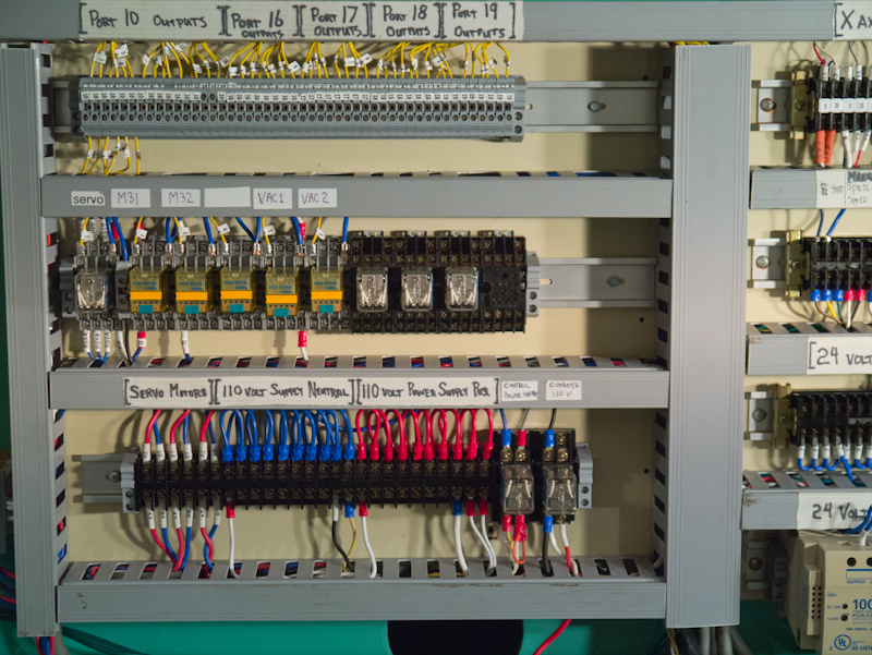
Mostly inputs in this portion of the cabinet. Again, labeled in the same manner as the outputs. There are two 24vDC power supplies, which run off 110vAC. The 100watt supply powers inputs and outputs, while the 50watt supply powers the controller. The 100watt supply is on from the moment that the machine is plugged in (in my case I run it off of a 30hp phase converter to get my 3 phase 240vAC). The power switch on the control panel sends power from the 100watt supply to the Control Supply relay, which then supplies power to the 50watt supply, powering on the controller. The power switch also activates the computer relay, which sends 110vAC to the computer, causing it to boot up into Mach (in startup folder). I'm still working on a way to automate the shutdown of Windows:
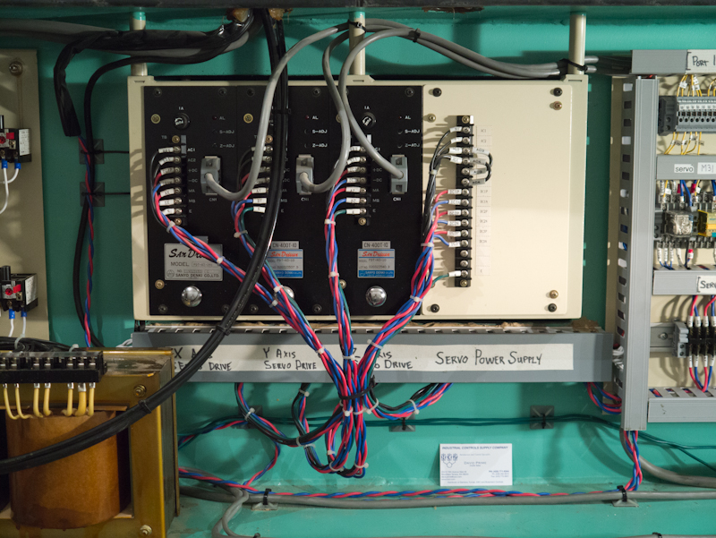
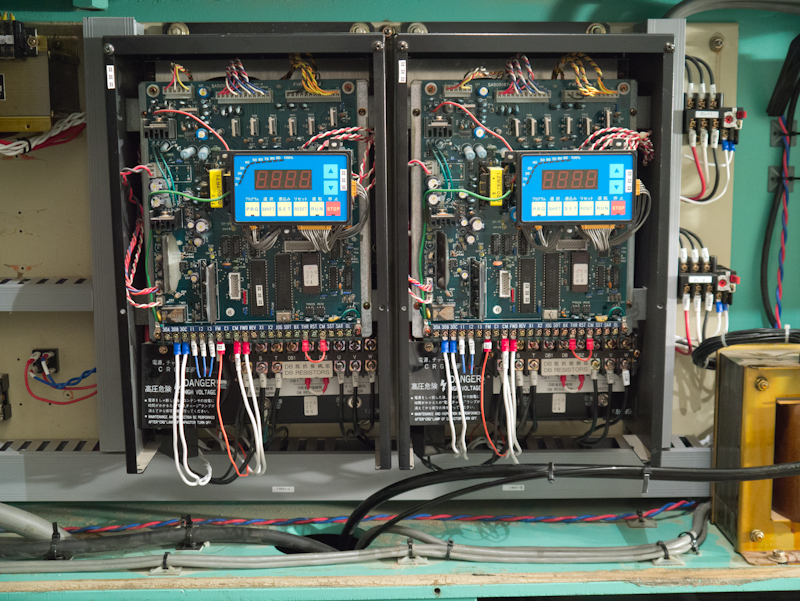
Sanyo Servo Drives (operational) and Fuji 7.5kw VFDs (not yet operating):
The only thing I'm trying to figure out at this point is where to send the Common signal from the VFD's. Since I'm using two power supplies, I think that I need to send it back to V- on the 50watt supply, since the analog signal is sent via internal power from the controller, which is in turn supplied by the 50watt supply. However, the digital outputs that signal other parts of the VFD (FWD/REV, Fault) are tied to the 100watt power supply, so it may be that the common needs to go there. I need to map it out to be sure. The VFD also states that certain pins at the drive are not isolated from it's logic common, so that may be a problem. If the analog and digital inputs on the VF drive share a common or do not have an isolated common, I'm not sure what is best practice when my control has isolated supplies. This may be an argument for having a single 24vDC supply, which may be my only option in the end (short of getting different VFDs).
Last edited by mmoe; 06-26-2013 at 01:25 PM.
Here's a quick video of the machine operating. The servos are about 90% of the way tuned now, with only some very subtle fluttering of the encoder when viewed in the CS Labs plug-in. For all practical purposes, the minimal error currently registering is insignificant for a router (+/- .001 approx.). I think it can be better though, so I'll keep working on the tuning.
Looks to be working well, maybe try and get a wee bit higher on accel if possible but other than that it looks great.
Seems quite a bit but suppose it depends how course the screws are and what gearing you have but as you said for a router it is likely a non-issue.For all practical purposes, the minimal error currently registering is insignificant for a router (+/- .001 approx.)
Hood
 Posting Permissions