Retrofitting a Shinx CNC router with CSMIO IP-A - Page 2

Page 2 of 4 FirstFirst 1234 LastLast
Results 21 to 40 of 68

Thread: Retrofitting a Shinx CNC router with CSMIO IP-A

  1. #21
    Member
    Join Date
    Sep 2012
    Location
    Seattle, WA USA
    Posts
    1195
    Downloads
    0
    Uploads
    0

    Default

    Is that the accel in "motor tuning" under the Mach config settings? I have it set pretty conservatively and will try upping it a bit. It's currently at 500 for X and Y and 250 for Z, which makes for a pretty flat graph for all three. When I first started up the machine, the servos would go into fault at the slightest movement of the axis, so I'm slowly turning everything up.

    The ball screws for X and Y are 20mm leads, and the encoders are only 500ppr before the 4x multiplier. All axis are direct drive, so no gearing from the motor to the shafts. With the 4x multiplier, the resolving power of the machine on each of those axis is .01mm, or .0004", but that's if everything was as perfect as the theoretical maximum resolution. While watching the position error in the plug in, it averages in the 4 to 5 encoder count range with the odd spike up to 15 for a really harsh change of direction (would never be programed that way at those speeds), which gives it that plus/minus .001" resolution on average. The Z axis is a 10mm lead, and it stays rock solid with the least amount of position error (often 0), so the additional mechanical resolution clearly helps. I'm sure further tuning will reduce the X and Y position error even a bit more, particularly those spikes, but I think there will always be a hardware limitation there as well.

    I think that the reality of any production level CNC router is that they aren't made to hold a tolerance any tighter than .001". Their purpose is to make things very fast, with a reasonable but not critical degree of accuracy. The 1000rpm motors are somewhat of a drawback currently, as the fastest rapid is still only going to be 20m/min, and I've got the maximum feedrate set to 15m/min (half of those numbers for the Z axis). Back in the late 80s, early 90s, these speeds were considered very good and typical, but now are on the slow side. 60m/min would be more like it these days, which could be done with 3000 rpm servos, but a typical feedrate will be less than the current limitations anyways (10m/min is about the maximum for the easiest to cut manmade wood materials (melamine/MDF) at 18,000 rpms), so only rapid positioning would be increased. In reality, for the one man small shop like myself, there would be little efficiency gained with faster motors, it would just look really cool for those rapid positioning moves.


  2. #22
    Member Hood's Avatar
    Join Date
    Oct 2004
    Location
    Scotland
    Posts
    832
    Downloads
    0
    Uploads
    0

    Default

    Yes the accel in Mach.
    For me Accel, up to a point, is more important than rapid speed as it will allow your actual cutting to follow more precisely when using CV. The 500 you have I presume is mm/s/s. Thats not too bad at all but if you could get the 800 to 1000 mark then I think it would be better.

    Hood


  3. #23
    Member
    Join Date
    Sep 2012
    Location
    Seattle, WA USA
    Posts
    1195
    Downloads
    0
    Uploads
    0

    Default

    Thanks Hood, that helps to have some general idea as to what is a good setting to shoot for. I'll try upping the acceleration to around 750 to start with later and see if the servo drives will tolerate it now that they are fine tuned.

    I spent the day fine tuning the servos and have got them dialed in pretty well I think. They stay right on their target now, with no fluttering at all. On the X axis, there is a maximum error of about 8 encoder counts during a movement at full rapid speed, with acceleration set to 100% in the CS Labs plug in. Turning down the acceleration and speed to 50% also cuts the error down by about the same 50%. The error generally appears to be in the acceleration portion of the motion, after which the error indicator stays between -1 and 1, often right at 0. Once the destination has been reached, it very quickly lands on 0. The Y axis is similarly around a maximum error of 6 encoder counts, and the Z axis has an error of about 9-10 encoder counts. Again, in both cases it seems to be right at the initial acceleration of the motion. After the initial acceleration, all axis seem to settle to be right at their targeted path.

    For what it's worth for those who may just be starting this process, the advice I would give on tuning the servos is to do it manually and do it gradually. The auto tune did not produce a very close result in my case, YYMV. To test the axis, I used the manual positioning field (if you are using the plug in, it will make more sense). I would send the axis near one end of the axis, press "apply" to reset the max error counter, then send it back to the other end of the axis. I did this with the acceleration at 100% and feed at 100%. You will find that the max error is not the same both ways necessarily, but as you get closer to the right values, the errors generally equalize. I started by upping the the kP value by 100 at a time until it I could see the errors significantly reduced. I never heard or felt vibration when changing the kP as suggested, but at some point the errors started increasing, so that seemed to be the place to stop. I started adjusting the kI, beginning at 100 and increasing by 10 until the errors stopped decreasing and started increasing again. At that point, I started adjusting the kVff, again starting at 100, increasing by 25 until the errors stopped getting reduced. Once these initial settings are accomplished, then I go back to the top and fine tune the kP, adding or subtracting 50 until I find the least errors (again, you have to hit "apply" to reset the max error counter), then the kI adjusting by 5 up or down to see where the least errors are and then the kVff again, up or down by 5 to find the least errors. This may need to be done several times as I find an adjustment to one seems to need to be accompanied by an adjustment to the others until you are right at the point of being finished.

    I'll see if I can get some video of the plug in later, as I think this has been the most difficult part of the process so far. It's not entirely a science, it seems.


  4. #24
    Member Hood's Avatar
    Join Date
    Oct 2004
    Location
    Scotland
    Posts
    832
    Downloads
    0
    Uploads
    0

    Default

    Autotuning worked very well for me but it may be due to much higher count encoders that I am using. One thing that I find very interesting is the different values that people quote for tuning, mine are much smaller in comparison to a few I have seen, if I recall they are 1286, 17, 0 11.
    I would still like to tune my motors to the drives manually, I just set them with the drives autotuning and it was fairly good but when I get some time I want to see if I can tweak things a bit better. Its probably not needed as any machining I have done so far has been deadly accurate but I always want to just try and get things as tight as they possibly can be.

    Hood


  5. #25
    Member
    Join Date
    Sep 2012
    Location
    Seattle, WA USA
    Posts
    1195
    Downloads
    0
    Uploads
    0

    Default

    Are yours AC servos? Mine are 100v DC servos running on analog drives, so perhaps there is a variance depending on the types of motors used.

    Those numbers are pretty close to what the autotune did on my machine as well (1100, 50, 0 and 3 approx.), but no matter what I did at the actual servo drives while using autotune, they would oscillate back and fourth by .005-.010". This did not subside until I got the kP value up over 2500, and even then did not totally disappear until I got upwards of 3500. The kVff value seemed to be the second most important adjustment in my case, and it had a pretty significant effect on max errors. It seemed like the kI value had a little more influence on stabilizing the axis at the deceleration end, but I would call that anecdotal at best.


  6. #26
    Member Hood's Avatar
    Join Date
    Oct 2004
    Location
    Scotland
    Posts
    832
    Downloads
    0
    Uploads
    0

    Default

    Yes mine are AC, they are 565v motors.

    I hope to get a chance to mess with the tuning a bit today and I will try increasing to some higher values, but first I am going to increase the simulated encoder output from the drives. Initially it was at the default 4096 counts per rev and I noticed a big difference when I interpolated them to 15,000. that was almost the max I could interpolate. The max output of the drive is 1.6MHz for the sim encoder outs and as the max RPM of the motor was set at 6000rpm that meant 16,000 would be the max. The motors are 4000rpm cont rating and thats what I use to get the 20m/min so if I drop the max rpm in the drive to 4000 that will allow me to get 24,000 counts per rev which will give me a step/mm of 4,800.

    Hood


  7. #27
    Member
    Join Date
    Sep 2012
    Location
    Seattle, WA USA
    Posts
    1195
    Downloads
    0
    Uploads
    0

    Default

    I only get 100 pulses/mm, and I do have to wonder still if getting better encoders would make the machine run just that much smoother. The controller really doesn't have that much to go on for positioning! For a small investment of about $150, I do wonder if these would work better:

    High-Torque Stepper Motor, Stepper Motor, Driver, Stepper Motor kit, DC Servo Motor, DC Servo Motor kit, Stepper Motor Power Supply, CNC Router, Spindle, and other Components. Automation Technology Inc

    I've read good things about those encoders, and they would offer around 5 times as much ppr than what I have now.


    Otherwise, I've been spending my time considering the conundrum of what to do with the VFDs. The common wire running back to the analog portion of the controller (for the +/- 10V signal) is not in any way connected to the common wire for the Forward/Reverse signals which come from the digital size of the outputs. The digital outputs are powered by a separate power supply from the controller, and the analog outputs, unless I'm mistaken, are powered by the controller's internal power supply. The real problem is at the Fuji VFDs, which do not have an isolated common for the analog inputs vs. the Forward/Reverse inputs. In fact there is 100% continuity between them. If I were to wire the analog common back to the controller, and the digital common back to the second power supply, it would bridge the commons of the two power supplies. I don't know for sure if that would really make a difference (I'm not an expert in electronics when it comes to isolating power supplies), but it seems the ideal situation is to have a shared common via the use of the same power supply. My solution is that I've changed the power supply to digital outputs (Port, Pin) 10,9 through 10,12 to the same power supply that the controller runs on. I'll still run the analog common back to the 10,20 analog outputs common pin, but also the digital common back to the power supply common. I think this will avoid any unwanted issues and all the other digital outputs will remain on isolated power from the controller power. For now, I'll be using only digital output 10,9 to signal Forward rotation to both VFDs, which is sent through the Spindle Down relay for each head. This will allow both to function simultaneously (via M33 code), or independently (via M31 or M32). However, it will limit the spindles to being on only when the head is lowered. In the future, I can see a time when being able to operate the head with the spindle up would be useful, but that can always be bypassed on a special occasion when needed and it's probably safer the way I've set it up now.

    I also spent yesterday writing up a post processor to match what I've done with the heads. I use Bobcad, which has had it's ups and downs over the years, but one thing that Bobcad has always had a leg up on is customization. My last machine had such difficult programming requirements that there were few companies who could even produce usable code. Bobcad was the only one for under $10k at the time, so that's where my Bobcad journey began. Prior to that, my favorite software to use was OneCNC XP Mill Pro, but they were unfortunately unable to give me a useful post processor.

    At any rate, I have now written a post processor that will automatically assign the correct work coordinate system for each of the three possible tool conditions. The first being that head number one is down. All I have to do, is specify in the software that I want tool number "1", and the post processor generates a G54 M31 code (M31 being my Head One Down code). If I want to use head number two, I specify tool number "2" and the post generates G55 M32, which allows me to align the cut of head two with head one. If I want to run dual parts machining, where each head has the same part, I just align the heads manually in the Z axis with the calibration dial, and ask for tool number "3" in the code. The post processor then generates G56 M33 in the spindle commands, which lowers both heads and should turn both spindles on. So far, in dry runs the code is perfect and the machine is switching between the work coordinates exactly as it should providing aligned motion from tool 1 to tool 2.

    On my list was to add a tool changer to the machine. I have a 10hp ATC spindle sitting around that could replace head one or head two. After seeing how well the post processor is working for multiple heads, I now am thinking that it may be better to have nine individual heads than an 8 position tool changer (which is kind of the standard for routers). For one thing, if the tool changer head fails, you're done until you get it fixed. Second, getting a head like that fixed is extremely expensive. I feel a bit like getting robbed when that's the case, but it is what it is. The cheapest replacement you'll find is $3500, so $2000 to get it fixed is still a "bargain". I think the head I have sitting here runs around $10k new. Third, a 10hp head is really overkill. A 5hp head is more than enough and will still break the bits without slowing down. I'm thinking that for the relatively modest accuracy needed for my line of work (wood shop as opposed to machine shop), the $275 4kw Chinese air cooled spindles may be good enough. 9 of those won't break the bank, and if one of them fails you have 8 more running, not to mention that it's only a $275 investment to replace the entire motor. I know they almost certainly aren't as nice as the spindles I have now, but they do have their upside too. I'm thinking I'll buy one to see what they are like. If the run-out is acceptable, and it seems to be durable enough to pay for itself, I can see putting together a large multihead array of them. I can even envision having a 4th axis just to position pairs of them for toolchanging during multipart cuts where 2 or even 3 heads are working at the same time. With nine heads, a person could run a three tool job while making three parts simultaneously.

    After my last machine, which had a tool changer, I'm not sure how long I'll last with a two tool machine as it is now. I'm definitely too lazy to be changing them by hand all the time!


  8. #28
    Member
    Join Date
    Sep 2012
    Location
    Seattle, WA USA
    Posts
    1195
    Downloads
    0
    Uploads
    0

    Default

    Turns out that the design of the VFD was a bit different than I thought. Rather than supplying a signal to the Forward or Reverse pins, you just need to close the FWD/RVS pins to the Common. The pins themselves have their own power supply, so once closed the VFD is ready for either forward or reverse revolutions, and then only needs the +0 to 10v command signal for RPMs. This also means that there is no need to worry about power supplies being criss-crossed, and I can restore the digital outputs to the larger power supply as it originally was installed.

    Once I figured this out, I ran the M3 output to a relay instead, which then closes the FWD/Common loop. This loop also runs through the M31 and M32 relays, so only a head that is lowered is able to start rotating. At this point, the spindles are working properly and run between 3500 and 18,000rpms. I have to double check the specifications though, as it may have been 3000-20,000 rpms originally which may mean either changing the settings in Mach to match or adjusting the VFDs to match my preferences. Either way, I think it may be slightly off for now, but very close none the less. Now that the machine is capable of cutting something, I'll be machining the main control panel PCB board so that I can transfer the buttons and new LED indicators (with resistors) and convert the panel to a simple matrix format. Otherwise, I can currently position the machine accurately with speeds exceeding original, the axis can be manually jogged using the original equipment jog panel, the spindles operate and can be automatically programmed with my Bobcad post, and the vacuum pump is working and programmable. At this point, if a job came in tomorrow, I could cut it (albeit with a few growing pains no doubt!). Everything from here out is gravy for improving the interface and expanding capabilities beyond the current minimum level.


  9. #29
    Member
    Join Date
    Sep 2012
    Location
    Seattle, WA USA
    Posts
    1195
    Downloads
    0
    Uploads
    0

    Default

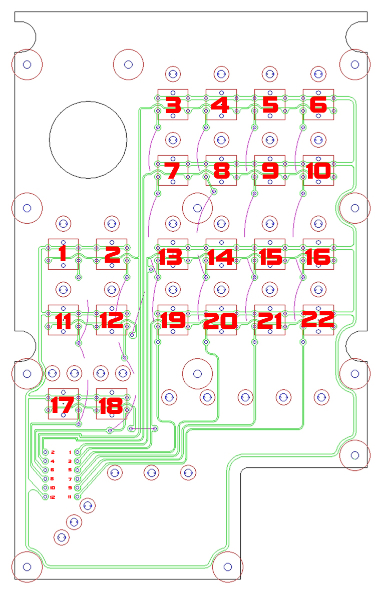
    Drew up a button panel matrix PCB circuit, which I'll be cutting out in the next couple of days. I only have some one sided PCB material on hand, so I designed it to use one PCB for the buttons, with jumper wires running across in places to allow for the matrix (usually this is easier with 2 sided PCB). I will also machine a separate second PCB for the LEDs, so they aren't on the same board. The button panel board will have mounting holes for the LEDs to pass through to a second board, where they will be soldered into a circuit. In order to fit everything needed, including the appropriate resistors, there simply isn't enough room on one board to do everything with the cutter I have (.6mm end mill). The red lines are construction lines helping me to know what may be in the way, or where the extents of physical objects are (buttons, leds, mounting areas, etc). The green is the "wire" tracks and there are pink dashed lines that represent jumper wires that will be soldered in to complete the circuit. Obviously the actual DXF file is a bit more clear.


    The circuit above will produce a matrix that uses only 10 inputs to provide 22 functions, so it's pretty efficient. There is still some scripting to write (I don't think I have enough built-in Mach 3 inputs to do this with brains, but it would be easier if I do or if I can define inputs by port/pin) but this is a pretty simple process. Matrix buttons are described by a combination of two buttons. A single button will produce the same input as the other buttons in it's row or column, so need to have both a row signal and a column signal to know which specific button was pressed. Here's some information about my specific button matrix, and how it eventually plugs into CSMIO I/O module inputs:

    24v supply to Pin 12 (common pin)

    Row 1 = Pin 4 (buttons 1,2,3,4,5,6)
    Row 2 = Pin 2 (buttons 7,8,9,10)
    Row 3 = Pin 1 (buttons 11,12,13,14,15,16)
    Row 4 = Pin 3 (buttons 17,18,19,20,21,22)

    Column 1 = Pin 8 (buttons 1,11,17)
    Column 2 = Pin 6 (buttons 2,12,18)
    Column 3 = Pin 5 (buttons 3,7,13,19)
    Column 4 = Pin 7 (buttons 4,8,14,20)
    Column 5 = Pin 9 (buttons 5,9,15,21)
    Column 6 = Pin 11 (buttons 6,10,16,22)

    Pin out to input port/pin assignments in CSMIO I/O expansion module (this is of course specific to my own designed button circuit, however the same idea applies to all matrix button panels):

    Pin 1 = Input 17/0
    Pin 2 = Input 17/1
    Pin 3 = Input 17/2
    Pin 4 = Input 17/3
    Pin 5 = Input 17/4
    Pin 6 = Input 17/5
    Pin 7 = Input 17/6
    Pin 8 = Input 17/7
    Pin 9 = Input 17/8
    Pin 10 = not used
    Pin 11 = 17/9
    Pin 12 = +24 Volts

    Button combinations:

    Button 1 = Input 17/3 and 17/7
    Button 2 = Input 17/3 and 17/5
    Button 3 = Input 17/3 and 17/4
    Button 4 = Input 17/3 and 17/6
    Button 5 = Input 17/3 and 17/8
    Button 6 = Input 17/3 and 17/9
    Button 7 = Input 17/1 and 17/4
    Button 8 = Input 17/1 and 17/6
    Button 9 = Input 17/1 and 17/8
    Button 10 = Input 17/1 and 17/9
    Button 11 = Input 17/0 and 17/7
    Button 12 = Input 17/0 and 17/5
    Button 13 = Input 17/0 and 17/4
    Button 14 = Input 17/0 and 17/6
    Button 15 = Input 17/0 and 17/8
    Button 16 = Input 17/0 and 17/9
    Button 17 = Input 17/2 and 17/7
    Button 18 = Input 17/2 and 17/5
    Button 19 = Input 17/2 and 17/4
    Button 20 = Input 17/2 and 17/6
    Button 21 = Input 17/2 and 17/8
    BUtton 22 = Input 17/2 and 17/9


  10. #30
    Member Hood's Avatar
    Join Date
    Oct 2004
    Location
    Scotland
    Posts
    832
    Downloads
    0
    Uploads
    0

    Default

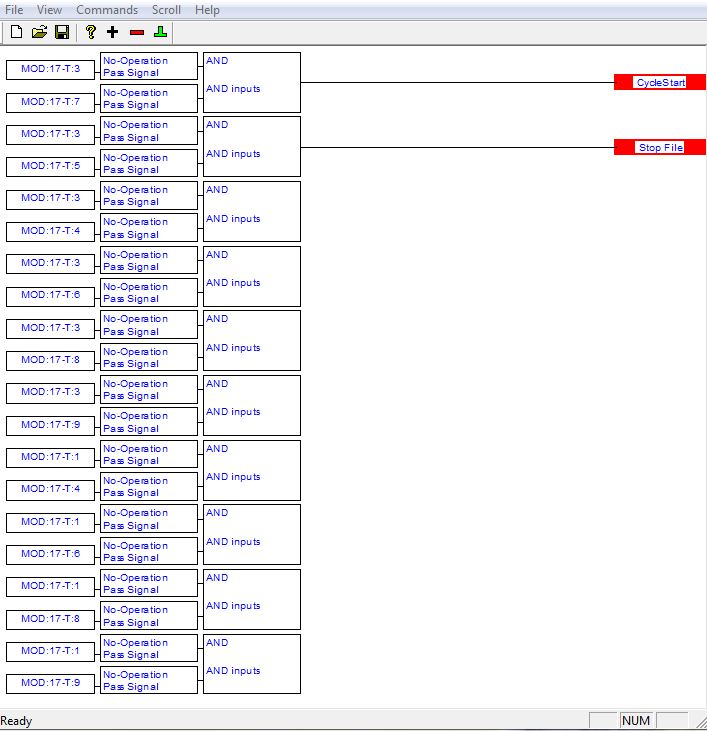
    There is still some scripting to write (I don't think I have enough built-in Mach 3 inputs to do this with brains, but it would be easier if I do or if I can define inputs by port/pin)

    You should be able to use Brains without setting the inputs in Mach, ie use the modbus address/bit in the brain as the input.
    Hood


  11. #31
    Member
    Join Date
    Sep 2012
    Location
    Seattle, WA USA
    Posts
    1195
    Downloads
    0
    Uploads
    0

    Default

    I've had a difficult time getting Modbus to work properly through brains. Is this how it should look? I think I may be getting bit and CFG# mixed up, as I've been using CFG# as the pin number and the Modbus address as the port number. I may still have to work in scripting though, as I need to pass the combined signal to an M code for many of the buttons, since they are not standard Mach 3 functions.


  12. #32
    Member Hood's Avatar
    Join Date
    Oct 2004
    Location
    Scotland
    Posts
    832
    Downloads
    0
    Uploads
    0

    Default

    You would find the address of the module then the input number, so say for example the modules address was 100 and it was input 8 then you would do as in the screenshot for the Brains modbus setup.
    Hood

    Attached Thumbnails Attached Thumbnails Retrofitting a Shinx CNC router with CSMIO IP-A-screenhunter_01-jul-02-22-17-jpg  


  13. #33
    Member Hood's Avatar
    Join Date
    Oct 2004
    Location
    Scotland
    Posts
    832
    Downloads
    0
    Uploads
    0

    Default

    Oh and you can use both Brains and the macropump at the same time if you wish.
    BTW best to keep Brains fairly short and just have multiple ones, if you get too big it gets very hard to view them when trying to troubleshoot.
    Hood


  14. #34
    Member
    Join Date
    Sep 2012
    Location
    Seattle, WA USA
    Posts
    1195
    Downloads
    0
    Uploads
    0

    Default

    Thanks Hood, I had the port number right, but the pin number in the wrong field. I'll get back on that after I finish up with the control panel PCB and see if it works correctly then. I think I'll be machining the PCB tomorrow as the last hurdle to machining parts is almost complete. That would be the vacuum table, which I've spent the day refurbishing and upgrading.

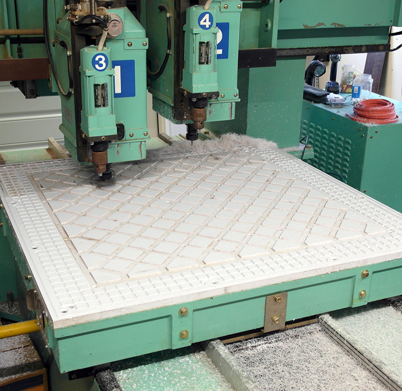
    The original table is only about 43" square, though the travel is considerably more than enough to cover a 50 inch square table completely with both heads when spaced 12inches apart. I'll eventually be changing the entire table out for a 50x98" table, so I'm just getting the one I have working well enough to start cutting some jobs and products. The plastic is, from what I can tell by smell, 3/4" PVC and somewhat brittle. The vacuum system was odd, in that there was a 4 inch perimeter in which there are no channels for vacuum. I've found that it's not uncommon for even high end machines from the late 80's and early 90's to have poorly designed vacuum tables. It's almost like they are an afterthought, and designed by people who have never actually used one for nested based routing.

    As I'm sure there are many machinist users that may read this, I'll cover the basics. For a CNC router, you need to use a sacrificial MDF board (wasteboard or spoilboard) on top of the table so as to allow unobstructed access to cutting the entire machine envelope. The vacuum system is beneath the MDF and pulls vacuum right through it. There are a couple of important components of a good vacuum system, the first being a pump that can do the necessary work when the vacuum drops. Vacuum pumps are a bit counter-intuitive. They draw less current when they are pulling a high vacuum, say 26 inches of mercury. As you cut your parts, you open areas of the wasteboard up and after a while enough vacuum is lost to drop down to perhaps 20-22inches of mercury. At that point, an underpowered pump will start to draw enough current to overheat, and possibly shut down before you are finished cutting. Remember that it takes more effort for the pump to move air than to move nothing, and when the vacuum is high, the pump is moving next to nothing and doing very little actual work.

    The second thing you need is a well designed table. I've used a few different machines over the years and I can tell you that there is a big difference between a good vacuum table and a bad one. It's becoming less common now, but you used to see tons of low end routers with air-hockey style tables. This does next to nothing for holding parts down. You can have a very high level of vacuum, but if there is no actual volume of vacuum (space) beneath the work then there will be little real force applied to the part. In my experience, vacuum tables need considerable channels of air beneath the spoil board to function well. This is sometimes misunderstood by novices as a way to allow more air to travel through the system, and a novice will often try to help that process by using ultralight MDF, which is more porous. In my experiments, I've found that you hold parts down better with a denser, less porous MDF because it reduces the air flow (vacuum leak) and increases the level of vacuum achieved beneath the wasteboard. Air movement though the MDF does not equal more holding power, but rather less and strains the vacuum pump.

    With all that in mind, I do have a highly capable vacuum pump for the current table size, but the table surface itself would not have worked well. I drew up some additional air cavities and a new perimeter in which to run a rope gasket so that the vacuum would cover more of the table. After I felt I had done as well as I could with what is already there, I cut the new vacuum runs into the table in that outer 4" of flat table, which you can see as a different small square pattern from that in the middle of the table. After the vacuum channels were cut, I then skimmed the entire table down by .5mm as it had quite a lot of abuse over the years. It should now work well enough to run some nested parts and I'll be putting an MDF wasteboard on later tonight. Once the wasteboard is planed down as well, I'll then be able to easily cut out the PCB panels for both the buttons and the LEDs.


  15. #35
    Member Hood's Avatar
    Join Date
    Oct 2004
    Location
    Scotland
    Posts
    832
    Downloads
    0
    Uploads
    0

    Default

    Thanks Hood, I had the port number right, but the pin number in the wrong field.
    I am not sure if you really did, it would seem you have the Canbus address in your example above. It is the Modbus address you need, ie for an expansion module it is the address as set by the jumpers for that module plus 100 so can be from 100 to 115.

    Hood


  16. #36
    Member
    Join Date
    Sep 2012
    Location
    Seattle, WA USA
    Posts
    1195
    Downloads
    0
    Uploads
    0

    Default

    Ah, I'll have to read some more then. Until I finish the control panel up, it will be hard to test things out anyways, so I've got time to do some research and get a better understanding. Thanks for pointing me in the right direction!


  17. #37
    Member
    Join Date
    Sep 2012
    Location
    Seattle, WA USA
    Posts
    1195
    Downloads
    0
    Uploads
    0

    Default

    Here's another video of the router, this time in action. I've got the wasteboard on and needed to surface it to get ready for the control panel PCB cuts. The cutter is a 2.5" flycutter and the feedrate/spindle RPMs are 10,000mm/min and 15,000 rpms. It ended up very smooth, so I think I could up the feedrate to 15,000mm/min and still have a suitable surface for vacuum hold-down. There are literally no tool marks, so you can run your hand across and only feel the change of direction of the slight fuzz that MDF always has on open faces. You can see the pattern pretty well, but it is kind of a velvet effect. There is no actual ridge from pass to pass, so at least I know the head is well squared up to the table when stepping the Y axis. I'll have to run it the other way later to see what the finish is like that way, but I don't expect that it will be any different really. When I planed down the table surface last night, you could make out the flycutter tool marks in both directions, like criss-crossed C's, which I take for a sign that the cutter is cutting about the same on the backside as the frontside.

    The vacuum system worked very well, drawing considerably less than the rated current in all conditions (wasteboard completely covered and wasteboard completely open). The range is from 20in/hg to 24in/hg, which is a bit lower than I've had in the past, but no problem so long as the motor isn't over-worked. The rating is approx. 20 amps and I'm only drawing around 15 amps max. based on my amp clamp meter readings. The vacuum level was just a little over the minimum recommended operating range by the manufacturer (12 o'clock on the gauge in the video), so as you can imagine a more porous piece of MDF would probably bring it below that level. Even with a completely open table, I was able to get very good holding power on the 8x10 (or so) piece copper plated PCB. By covering the unused table with plastic, it will be even better. Overall, while I wish the pump had a little deeper vacuum ability, it does seem to be powerful enough and will probably be very reliable. It does need a relief valve solenoid for shut down though, as it tries to turn the pump backwards if you just shut if off since that's the only place it can draw air in from. Ideally, I'll put a large solenoid that will open with a 2 second dwell prior to the pump turning off as part of it's canceling M-code. This will let it decompress (or re-compress rather) without drawing air through the pump backwards, which I just don't think is good for it.

    Hopefully tomorrow I'll have a video of the PCB being cut!


  18. #38
    Member
    Join Date
    Sep 2012
    Location
    Seattle, WA USA
    Posts
    1195
    Downloads
    0
    Uploads
    0

    Default

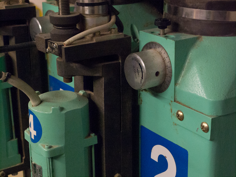
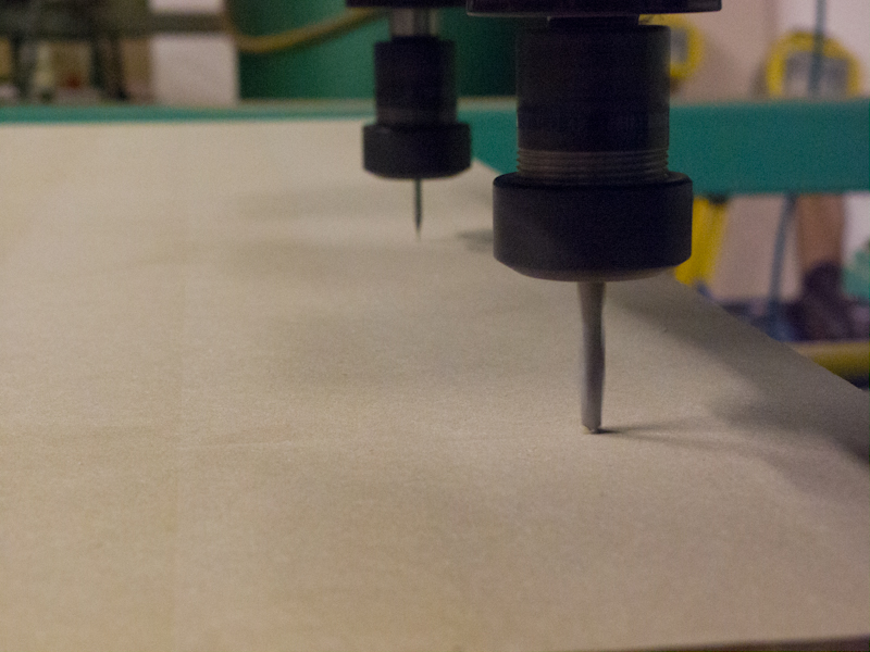
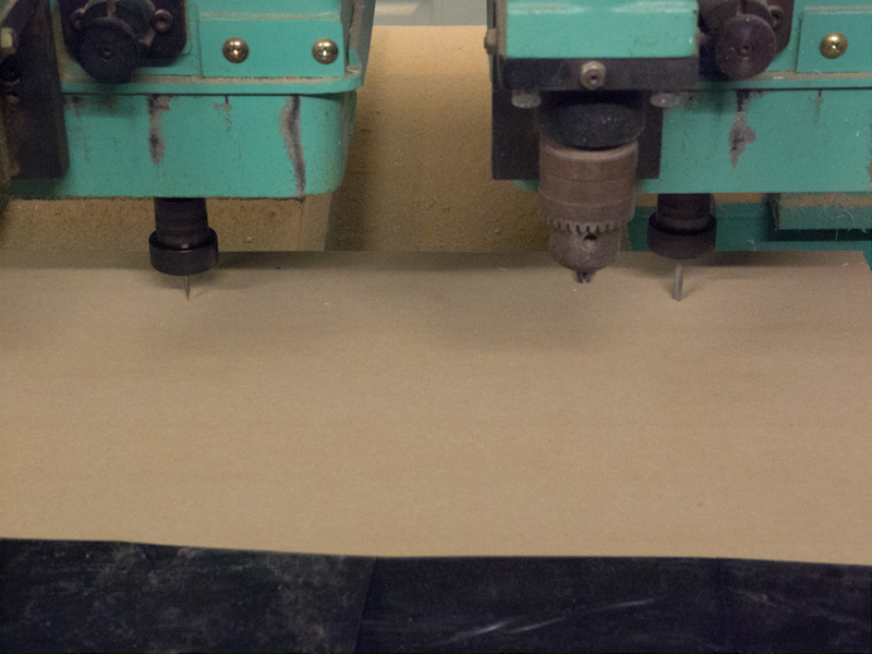
    I've finished with the programming and setup for the PCB and I'll be machining it in the morning. I don't have automatic tool touch off, but one nice thing about this router is that it has a great manual calibration system for setting up the spindles. I'm using two tools for the PCB, one .025" end mill and a .25" spiral router bit (just for cutting the perimeter and the large hole for the power switch clearance). They are similar in length, within about half an inch when installed in the collets so I decided to take the time to calibrate them both to the same depth. The heads are spaced around 12" apart and have been measured and entered as an offset for the second head. The spindle height, however, is adjustable so long as the bits are reasonably similar in length by simply turning a knob to adjust the height of the head in relation to the Z-axis. I lowered the heads and set the bits close to each other, then used the knobs to dial in the exact depth. The resolution of the adjustment is .01 mm, so it is very easy to get them just touching the surface of the wasteboard enough to mark them, but without enough depth to really even feel it with your fingers, almost like it has drawn a line with a pencil. You could make a similar mark by dragging your fingernail in a line, so I'm extremely pleased with how simple it is to set this up.

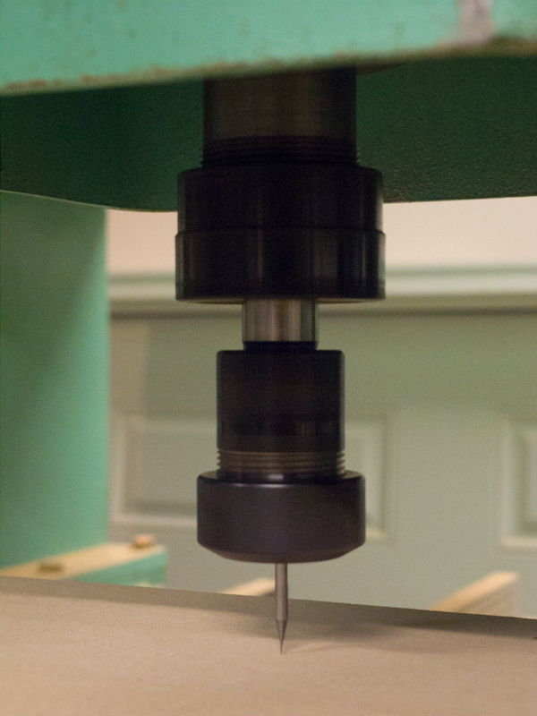
    I should also mention something that you may notice in the photos. The machine's original spindles use a YCC 20 collet, which is a real pain in the rear to find and expensive when you do. They are reportedly great collets, but not very useful if you can't get your hands on enough of them to get work done. All that the machine came with is two 3/4" collets, one for each head. I found that the logical and economical solution was to buy a 3/4" straight shank collet holder in a more common variety, so I now just use ER-25 collets. If I ever need something bigger, well I've already got the 3/4" range covered and I can't image a bigger shank on anything used in a router. The collet holders I bought are sold by "Gromax" through the bay. I think they are fabulous and my fears about having additional run-out are no more. They run very smooth and true, so I couldn't have asked for more. The nice thing about using these holders is that I can adjust the tool lengths to help even them out when calibrating the lengths.


  19. #39
    Member
    Join Date
    Sep 2012
    Location
    Seattle, WA USA
    Posts
    1195
    Downloads
    0
    Uploads
    0

    Default

    Well, broke the .025" bit I was planning to use, so I'll have to wait for another. I did some test cuts on some scrap phenolic with no issues, but when I cut the PCB at the same rate it broke instantly. I almost increased the feedrates after the phenolic test, but it seems that the PCB material is considerably harder to cut. I'll have to slow everything down for the next try, though I also don't know if the bit was just at the end of it's life as I've had it for about 10 years. I really can't remember how much or how little it got used in that time, so no way to know if I should be disappointed or not.


  20. #40
    Member
    Join Date
    Sep 2012
    Location
    Seattle, WA USA
    Posts
    1195
    Downloads
    0
    Uploads
    0

    Default

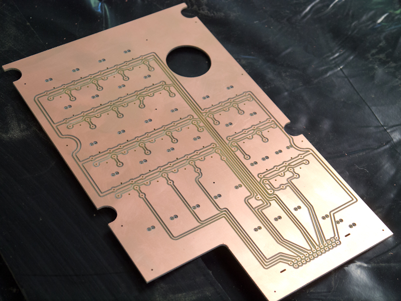
    I was lucky and a shop less than 20 blocks away had a bit set of 1mm, 2mm and 3mm German made carbide end mills/routers (they have more of a router shape to them IMHO). They also have a very efficient butterfly tip that worked very efficiently for boring. The suggested spindle speed is 20,000rpms, at which I calculated a 400mm/min feed rate. I dropped the RPMs and the feed rate to 15,000 rpms and 250mm/min, which I felt pretty good about. The new bit is a 1mm instead of .65mm, so I did have to change the setting in my CAM software and repost the program. Again, with the above adjustment to the Z-axis, I was able to dial the new bit in to match the old one precisely.

    I've never tried to machine a PCB, so I'd done a fair bit of reading in forums as to what others do and how it worked. It seems that the main issue is that most people find they aren't able to get a uniform depth of cut, due to the generally wonky plane that these come in, probably due to laminating a very heat sensitive material to a thin base. Mine was a bit cupped, but not so much that the vacuum couldn't pull down 95% of it, leaving only the outer most corners sitting proud of the wasteboard. Based on the experience of others, I opted to machine .5mm into the surface to be sure to catch everything. In retrospect, I could have probably cut that at least in half as the PCB material was cut evenly across the entire board. I'm guessing that no one that does this and posts their results has a vacuum system like this, as it really did not appear that there was any significant surface variation.

    If I reduced the depth of cut in half, I'm pretty sure that I could run at 500mm/min without straining the endmill. It also drills at 500mm/min very well, with no sign of strain. In the future, those will be my preferred settings: .25mm depth of cut, 15,000 rpms, 500mm/min (feed and plunge).


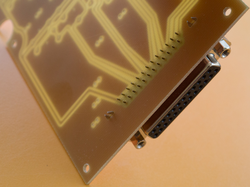
    Before machining, I had redesigned the circuit a bit to accommodate a DB25 plug. I'll only use half of the plug on this board, and may find a way to solder jumpers on to bridge to the LED PCB, which will be a second layer of circuit to this control panel, so initially it looks a bit backwards. Due to the space available, this was the best way I could install it. I'm pretty pleased with the fit though, and I don't think I could improve on it at all in that regard.


    I'll try to put a video of the machining together later tonight. At the very conservative speeds I ran, it took about half an hour to cut, so there is a lot of editing to do to get it down to a 1 or 2 minute clip.


Page 2 of 4 FirstFirst 1234 LastLast

Tags for this Thread

Posting Permissions

  • You may not post new threads
  • You may not post replies
  • You may not post attachments
  • You may not edit your posts
  •  


About CNCzone.com

    We are the largest and most active discussion forum for manufacturing industry. The site is 100% free to join and use, so join today!

Follow us on


Our Brands

Retrofitting a Shinx CNC router with CSMIO IP-A

Retrofitting a Shinx CNC router with CSMIO IP-A