3X3 Gantry router/mill project


Page 1 of 5 1234 ... LastLast
Results 1 to 20 of 89

Thread: 3X3 Gantry router/mill project

  1. #1
    Gold Member Bloy2004's Avatar
    Join Date
    Oct 2003
    Location
    Sturgeon Bay, WI
    Posts
    927
    Downloads
    0
    Uploads
    0

    Default 3X3 Gantry router/mill project

    Entry post:
    Some photos of parts and materials collection process.

    This will be the Yaxis Gantry with modifications for end support


    These will be the x axis glide for the gantry.


    This, with modifications will serve as the Z axis


    Similar Threads:
    Last edited by Bloy2004; 07-07-2004 at 06:53 AM.


  2. #2
    Community Moderator ynneb's Avatar
    Join Date
    Feb 2004
    Location
    Oz
    Posts
    2337
    Downloads
    0
    Uploads
    0

    Default

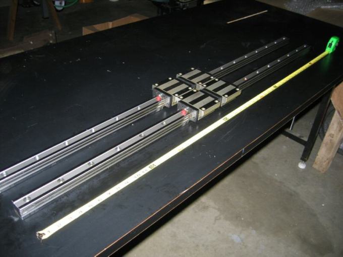
    Thats looking to be a nice collection of parts.
    Since you are only doing a 4 x4 table I am wondering if you should use belts.
    I only suggested belts so as to make it cheap. But you could use lead screws for that size.
    I guess all have their pros and cons. With screws you wont need as much down gearing as with belts.

    I think belts are only an alternative for long axis where you want to keep the cost down.

    Being outside the square !!!


  3. #3
    Gold Member Bloy2004's Avatar
    Join Date
    Oct 2003
    Location
    Sturgeon Bay, WI
    Posts
    927
    Downloads
    0
    Uploads
    0

    Default

    I'm wondering about those belts and drive ratios.... the motors I have are strong..those E712s. running with the higher encoders will reduce the speed maybe without being prone to faulting. And if I run them with lower voltage, I am thinking maybe their strength will offset the possible overheating. ....Pretty sure the Z axis will be screw though.... I still need a much clearer understanding of how all those elements play with each other. Otherwise, yes, I want to avoid all the pulley reduction setups if possible....maybe some properly ratioed gear motors will come along at a "can't pass up" price....
    In any event, over the months I've got now somethin' to work with that fits together relatively nice.

    Last edited by Bloy2004; 07-07-2004 at 09:59 AM.


  4. #4
    Registered
    Join Date
    Jun 2004
    Location
    United States
    Posts
    8
    Downloads
    0
    Uploads
    0

    Default

    Staying under 48", belts will work BUT, you may want to look into lead screws (I agree with ynneb). You can pick up NOOK leads with .003/ft. precision fairly cheap and all the potential (again I said potential) problems with the belts will be eliminated. If you have another $50 (or less) to spend you will see so much gain later on. Plus you can save the belts for future projects or sell them! You have made some very good purchases up till now and most likely things will be just fine. Hey, can I hire you to make purchases for me? I have been trying to pick up a set of rails like that (for that price) but never seem to get what I want. I usually buy new for my resale machines and there are plenty of great deals out there if you know where to look.


  5. #5
    Registered
    Join Date
    Apr 2003
    Location
    UK
    Posts
    1079
    Downloads
    0
    Uploads
    0

    Default

    Subscribed! Mate, if thing turns out like your last project, I will be watching every step of the way
    Now a few questions!
    Just wondering what you mean when you say higher count encoders will slow it down? Is this due to the 45Khz limit in Mach2? If so, then surely this will increase the likelyhood of a fault, since the geckos will only bear (bare?) a 128 pulse error before faulting, then 128 pulses could end up being a fraction of a degree - please excuse me if I am barking up the wrong tree, I have no idea what encoders you have, or even if you are using geckos
    Anyhow, I would love to see this machine run off of balscrews too, don't forget that Reid Tool will export from the USA for an extra $25 admin fee. Again, I have no experience with belts, but I think they are better suited to longer beds than 4 foot since ballscrews should still be affordable.
    Anyhow, don't let me put you off, it's gonna be great either way

    (Note: The opinions expressed in this post are my own and are not necessarily those of CNCzone and its management)


  6. #6
    Gold Member Bloy2004's Avatar
    Join Date
    Oct 2003
    Location
    Sturgeon Bay, WI
    Posts
    927
    Downloads
    0
    Uploads
    0

    Default

    Kong
    I've got Gecko 320's in the control station. Adapters are available for multipliers which might quell the ppr issue. The computer and power supply will be castered from the Shoptask to the router and reconnected. Multiple configurations can be saved to enable easy transition. But, I Have considered the Rutex drives....and another power supply.....just not for a while yet....$$.
    Noticing that the y axis(gantry) is already belt driven, I intend to experiment with this motion first. A static mount with the full 24 inch Z axis rails(don't want to cut them down yet) will be put together and numerous tests will ensue.
    Remembering that this is a hobby, the intent is not to simply build the machine, but to explore the multiple variations available. This will facilitate a better understanding of "the way things work". Hopefully I won't dawdle too much. Being a factotum, there is usually little time 'til winter. Going there has to be as rewarding as being there.
    Hmmm.....I reserve the right to alter my philosophical sensibilities at any time

    Last edited by Bloy2004; 07-07-2004 at 10:14 PM.


  7. #7
    Registered anoel's Avatar
    Join Date
    Apr 2003
    Posts
    470
    Downloads
    0
    Uploads
    0

    Default

    Bloy... You've got one major advantage that a lot of us don't... You've got a kick ass Mill/Lathe to work with...

    You can mill your own parts... Bearing blocks, spacers, Turn your leadscrews, make couplings...yada... yada.. yada...

    Nathan


  8. #8
    Gold Member Bloy2004's Avatar
    Join Date
    Oct 2003
    Location
    Sturgeon Bay, WI
    Posts
    927
    Downloads
    0
    Uploads
    0

    Default

    testing


  9. #9
    Registered HomeCNC's Avatar
    Join Date
    Mar 2003
    Location
    United States
    Posts
    779
    Downloads
    0
    Uploads
    0

    Default

    Bloy,

    Welcome to the router club We haven't talked in sometime. Call me if you want to talk about your project.

    Thanks

    Jeff Davis (HomeCNC)
    http://www.homecnc.info


    (Note: The opinions expressed in this post are my own and are not necessarily those of CNCzone and its management)


  10. #10
    Gold Member Bloy2004's Avatar
    Join Date
    Oct 2003
    Location
    Sturgeon Bay, WI
    Posts
    927
    Downloads
    0
    Uploads
    0

    Default Status report

    Geeesh it took months to get this far. And it's on top of another project that has to be completed first for my "work".

    But this is the basic configuration: raise it up about 2.5 feet (table and all) under a square metal tube frame. I'd like to do sculpting and have a secondary table insert for more stressful operations so the Z axis won't be "reaching " and have less flex while not extended so far.

    I feel lucky that I got most of these parts months (year?) ago because now the bidding on Ebay always goes way over MY budget.

    Attached Thumbnails Attached Thumbnails 3X3 Gantry router/mill project-mock-1-jpg   3X3 Gantry router/mill project-mock-2-jpg   3X3 Gantry router/mill project-mock-3-jpg  
    Last edited by Bloy2004; 05-09-2005 at 09:21 PM.


  11. #11
    Member ger21's Avatar
    Join Date
    Mar 2003
    Location
    Shelby Township
    Posts
    35538
    Downloads
    1
    Uploads
    0

    Default

    It's nice to know I'm not the only one taking forever to finish a router. I was going to ask you about this after seeing that post on Yahoo about it.

    Gerry

    UCCNC 2017 Screenset
    [URL]http://www.thecncwoodworker.com/2017.html[/URL]

    Mach3 2010 Screenset
    [URL]http://www.thecncwoodworker.com/2010.html[/URL]

    JointCAM - CNC Dovetails & Box Joints
    [URL]http://www.g-forcecnc.com/jointcam.html[/URL]

    (Note: The opinions expressed in this post are my own and are not necessarily those of CNCzone and its management)


  12. #12
    Registered
    Join Date
    May 2004
    Location
    United States
    Posts
    290
    Downloads
    0
    Uploads
    0

    Default

    I like the raised design you have going. Like you said, Z clearance will be more flexible. One question: Are you going to run dual screws on either side of the X axis? Or do you plan on just one side being powered? If you go with dual screws, how does everything get syncronized?(SP?) Through the software, or wiring or something else?

    Carlo


  13. #13
    Gold Member Bloy2004's Avatar
    Join Date
    Oct 2003
    Location
    Sturgeon Bay, WI
    Posts
    927
    Downloads
    0
    Uploads
    0

    Default

    yes, I plan on using two Geckos and Mach3 to "Slave" both sides with rack and pinion (not shown in pics) . Mach3 will do this and Art has several customers that are using this feature successfully. the X axis rails are really WAY stronger than the open bearing y and Z, but In time I'm sure I will find a way to retrofit THK rails and use the Thomson bearings for another project....but for now (and forever probably ) I'm going with what I have.

    Also, the Y axis is belt driven and am "in the process" of upgrading the belt. The old one seems of lessor quality and has more "stretch" than a good quality belt. I just lost out on a 4 ft ballscrew and nut on Ebay as it skyrocketed to more than what I could put out.

    Most of the sculpting done with the z axis extended will be of an artistic nature where tolerances won't be critical. And, I don't intend to be cutting much more than multiple passes in aluminum with the table insert and the Z axis retracted.


  14. #14
    Gold Member Bloy2004's Avatar
    Join Date
    Oct 2003
    Location
    Sturgeon Bay, WI
    Posts
    927
    Downloads
    0
    Uploads
    0

    Default Calculations

    I have (2) 12:1 gearheads and "made for" servo motors rated at 60V/Krpm (as seen in above pictures).
    I "Plywood-boarded" a power supply giving 95.6VDC and
    found the output shaft rotates at 132.8rpm. The motor shaft
    therefore rotates at 1,593.6rpm (12 X 132.8).

    Wanting to use an existing Gecko320 which cannot exceed 80VDC, I
    will apply 75VDC to the motor. In theory, this would bring the motor
    rpm down to 1,250rpm and gearhead shaft output at 104.16rpm (1250
    divided by 12).

    With direct drive, travel per 1 rotation of output shaft is 3.92857
    inches. Hence, 1 inch of travel will equal .254545 of 1 rotation.
    Multiplying this by 12 (gearhead reduction) yields 3.05454rpi
    (Revolutions of motor Per Inch of travel).

    If using a 500cpr (Counts Per Revolution) quadrature encoder, this
    translates to 2000ppr (Pulses Per Revolution). Multiplying this by
    the motor shaft rpi (Revolutions Per Inch) gives 6,109.08 pulses per
    inch of travel (2000ppr X 3.05454rpi).

    Changing the 1,250rpm of motor to revolutions per second yields
    20.8333rps (Revolutions Per Second). With 2000ppr encoder, total
    pulses per second equals 41666.67 (2000 X 20.8333).

    Mach3's max ppr is 45,000 so as figured this configuration should
    work with motor tuning setup at maximum velocity given ample power
    of motor.

    Inches Per Minute of travel (ipm) would be 409.2269 (1250rpm divided
    by 3.05454rpi)

    Assuming the motor has the power or the machine mass is within means,
    this all should work

    Originally the $30 per motor/reducer ebay buy was intended for only the gearheads, but
    the motors came with them and are in pristine unused shape.

    Bloy


  15. #15
    Gold Member Bloy2004's Avatar
    Join Date
    Oct 2003
    Location
    Sturgeon Bay, WI
    Posts
    927
    Downloads
    0
    Uploads
    0

    Default encoders

    the USDIGITAL E7MS was chosen (had no choice really) because it was the only size that fit the recess on the motor's back plate....a nice match.

    Attached Thumbnails Attached Thumbnails 3X3 Gantry router/mill project-e7ms-encoder-jpg  


  16. #16
    Registered
    Join Date
    Aug 2003
    Location
    Netherlands
    Posts
    114
    Downloads
    0
    Uploads
    0

    Default

    Wow, you have found some nice stuff at ebay. This is going to be one slick router. would it be difficult to convert the Yaxis to rack and pinion instead of upgrading the belt?

    John


  17. #17
    Registered
    Join Date
    May 2004
    Location
    United States
    Posts
    290
    Downloads
    0
    Uploads
    0

    Default

    Bloy,

    The more I think about this design, the more I like it. I keep imagining a seperate actuation for the table that allows it to be infinitely adjusted relative to the Z axis (to keep Z cantilevering to a minimum). The only concern might be accuracy of alignment (i.e. how to keep the table truly perpendicular to the Z). Alternately, I can imagine the table being comprised of a base on wheels that can be removed for clearance of larger work. Just dreamin' here...

    BTW, I'm including an image of a commercial design similar to yours (uptime.ca - now out of business?). They used a ballscrew on only one side of the X, which never conviced me... Also they seemed to skimp in using only 1 rail on the Y, but they swore by it.

    Attached Thumbnails Attached Thumbnails 3X3 Gantry router/mill project-left-side-uptime-cnc-f88da1-gif  


  18. #18
    Gold Member Bloy2004's Avatar
    Join Date
    Oct 2003
    Location
    Sturgeon Bay, WI
    Posts
    927
    Downloads
    0
    Uploads
    0

    Default

    cbass,
    You say that the business is no longer? I wonder if it had to do with the design of their machine. But I DO detect from the picture that both sides of the Xaxis seem to be driven by Ballscrews...just above the rail bearings.
    On the router I'm building (eventually), those side supports for the X axis will be integrated to the floor stand. I'm thinking of having each side modular and mount to the table module with gussets underneath, adjustable to achieve proper alignment along with floor pads to remove unevenness of floor variations.
    If I don't do this the machine will never make it out of the basement without doing some home reconstruction!
    Thanks for that Picture!

    Last edited by Bloy2004; 05-10-2005 at 11:52 AM.


  19. #19
    Gold Member Bloy2004's Avatar
    Join Date
    Oct 2003
    Location
    Sturgeon Bay, WI
    Posts
    927
    Downloads
    0
    Uploads
    0

    Default

    Here is the Ballscrew assembly I used for the Z axis. I got one from ebay "lisa_ctrsurplus" but the balls had not been circulating and the screw was useless. But I called them up, they said "keep that one..we'll send you another". Well, the second was in Dandy shape! And, I got an extra set of mounting blocks, thrust bearings and hardware from the first. To mount this I milled off the "tongue" of the ballnut bracket and tapped into the remaining smaller flange. the end blocks were shaved here and there and retapped to fit clearances behind the Thomson bearings. That "clutch" and the extra screw shaft were cut off. Also I shortened the Zaxis rail assembly by six inches to accomodate the ballscrew assembly.

    Attached Thumbnails Attached Thumbnails 3X3 Gantry router/mill project-ballscrew-assembly-1-jpg   3X3 Gantry router/mill project-ballscrew-assembly-2-jpg   3X3 Gantry router/mill project-ballscrew-assembly-3-jpg  
    Last edited by Bloy2004; 05-10-2005 at 12:46 PM.


  20. #20
    Registered
    Join Date
    May 2004
    Location
    United States
    Posts
    290
    Downloads
    0
    Uploads
    0

    Default

    Quote Originally Posted by Bloy2004
    cbass,
    ...But I DO detect from the picture that both sides of the Xaxis seem to be driven by Ballscrews...just above the rail bearings.
    You're right...I need to think before I type


    I think they are out of business because they lacked marketing skills (see K2CNC for tips on how to do this ) (aren't smilies FUN?)


Page 1 of 5 1234 ... LastLast

Tags for this Thread

Posting Permissions

  • You may not post new threads
  • You may not post replies
  • You may not post attachments
  • You may not edit your posts
  •  


About CNCzone.com

    We are the largest and most active discussion forum for manufacturing industry. The site is 100% free to join and use, so join today!

Follow us on


Our Brands

3X3 Gantry router/mill project

3X3 Gantry router/mill project