Reply with Quote
Chris;
I fell like this will work for me.
Hope you have a great week end and a happy Easter, and may God bless you, as he has me.
Dan


Good-o,
Strip board it is. :-).
FYI, my 'design target' for this is up to 10khz pulse rate from three motors simultaneiously. That'd give you 1500rpm half stepping (3000rpm full stepping) which equates to 75ipm with a 1/4x20 thread or 1.5m/m with M6/1 thread. (135ipm or 1.5m/m full stepping). That should be more than enough for simple machines, and gives loads of 'head room' for the processor to ensure things don't fall appart. :-).
There are some issues with a single processor monitoring three stepper inputs, so this type of design has an inherent flaw. Not an issue if you don't want to go screaming fast though! If you do want to go screaming fast, all that is required is a single, smaller processor per stepper motor, as per my original junk box design.
Cheers, Me.
Chris;
I fell like this will work for me.
Hope you have a great week end and a happy Easter, and may God bless you, as he has me.
Dan
Over the weekend...
Made up some 'anti-whip' bearings for the end of the lead screws out of LDPE plastic sheet, as per the first pic. The Y lead screw in particular has been going into wild oscilations when jogging... It's just a flat bit of plastic with a 6mm hole in the middle, nothing flash, but does the job.
Also added some more bits to the simple stepper controller. I mentioned before that there was an inherent flaw in using a single processor for three stepper drives. The main issue is that the processor could 'miss' the step input from an axis, while processing the step for another. which would give missed steps without having to over-speed or apply too much resistance to the motor, which is a bit silly. Each 'loop' through the software is only taking 5us, but it's still a problem if your pulse outputs are only 5us across..
I could have fixed it by saying 'you must use 50us pulse width output' but I googled mach3 and found it can only go up to 5us (That might be wrong, I just did a cursory search and found an article stating that) so I figured I had to fix it in hardware, as mach3 is pretty popular.
Anyway, 'cause I've currently got nema 17 steppers running on only 5V on the controller, they don't go fast enough to test up to my 10Khz goal. I wrote a test version of the software that requires 8 step pulses to get 1 on the motor. Now I can drive it at a higher frequency for testing, without having to use a bigger test setup. In real software terms, I'm using a lookup table which is normally 8 steps long, I made it 64 steps long, with the same data repeated 8 times.. Sort of like micro stepping without the steps!
Anyway, I wrote a quick program to generate some random gcode for soak testing the code, and left it running with the three steppers running at max 12Khz for just under an hour, and didn't drop a step.
The test code can be seen in the second pic below, and I even took a video, because I've just started using google video, and thought it might be cute.
http://video.google.com/videoplay?do...50368503616353
Next step is to clean up my bench and bring the junk box cnc machine in with it's PC and controller so I can stick this unit in to test with the larger steppers and power resistors in circuit. I also want to do some testing with emc, and maybe the demo of mach3, as just testing with turbocnc isn't a very good sample set, so to speak.
While the machine is on the bench I'll be putting limit switches on it, and putting an e-stop of some sort together, along with putting a couple of power relays in for spindle and dust collection. Call me lazy, but having to turn on the dremel by hand is sooo time consuming!.
I'm busy the next couple of nights, but I'll see if I can get the circuit diagram and bill of materials together for people to pick holes in before the end of the week.
Cheers, Me.
One draft schematic.... A meeting I was meant to be at was cancelled.
If you go to: http://ohmark.trash.co.nz/3step/ There's one PDF file, and the current eagle schematic file for those with eagle (I'm using the free version).
I've not uploaded it directly to the forums here, as I've seen comments about not being able to delete/edit posts after they get a bit old, and I don't want a draft diagram stuck on here, never to change... If it changes I'd prefer people were getting the newer version automagically.
In the schematic, the spindle relay drive and limit switch circuits are optional if you don't want them, and the jumpers I've shown can just be the pins on the IC connected to gnd or vdd. The F/H jumper (JP1) will set full or half stepping, open/high for half stepping, closed/low for full. You can ignore the 'spare' one, I put that in the schematic for the PCB version, just in case I thought of a need for another jumper!
The input schmit triggers are also optional, but you have to keep the resistor + diode + cap network which I'm using as a simple latch 'pulse stretcher' to get around the limitations of having 3 steppers on one processor. With the schmit triggers in place you need to set your 'step' signals to be 'active low' in your CNC software.
You can just drive the parallel port pins straight into the 1K resistor, although I can't say it will be reliable with all parallel ports or computers, and a 74HC14 should be under a dollar which is cheap reliability insurance.
I've labled this a draft as I've not actually found out how limit switches interact with EMC2 or other cnc software yet, so I might be off on that count, and becuase I've not added the E-stop latch and enable circuit yet which I want for my build.
I'll post the source code when I've done some more testing later in the week, if anyone is really mad keen to get this under way.
I'll also post some notes on power resistors, the power supply hookup, and general building of the thing.
The motors / power supply / power resistors are not shown in this either, but it goes without saying that if you drive your 3A 2V steppers from a 12V power supply without any resistors you're going to create smoke, and if you use a 24V power supply and poke it into the 5V supply for this circuit you'll also create a nice smoky haze in your workshop!!!!
Let me know if this is total gibberish.
I've added the limit switch functionality to the controller board for myself, as well as the spindle relay drive circuit and e-stop. I've updated the PDF of the circuit on my website at: http://www.ohmark.co.nz/3step
Also, as per the pic, I've got the driver mounted into the junk-box controller case, and tested.
And a video is worth a thousand (or more) words:
http://video.google.com/videoplay?do...47701240282258
I discovered some interesting things with emc2 (And I assume Mach, as it's based on EMC, although I've not tested with Mach yet).
You can't turn on the spindle output unless you've set a spindle speed, even though your spindle may not be speed controlled. You can waste a bit of time figuring out that...
And when you hit a limit switch, the spindle output dosn't turn off... Which I'll have to look into, as I would have thought the spindle would be turned off for any error condition.
Anyway, I've got it all running, the steppers in the video are doing 700rpm, equivalent to 700mm/min for my junk box router, or 28ipm with 1/4x20 rod for the imperial folks.. That is max speed for those steppers using the resistors I have in the box for the single-stack motors I used on the junk-box router. I suspect I'd get 1000rpm or there abouts with matched resistors rather than the ones for the smaller steppers.
Now that I've got it set up to test at 'high' power levels, I'll try it with TurboCNC and Mach3 to make sure it's all good, and then tidy up the source code, and post it to here. Taken a bit longer to get here as I've picked myself up a head cold, and have had some days sitting inside in the warm playing with the kids.
That, and I've been using whiskey to keep a very sore throat under control on a couple of occasions. Soldering and spirits dosn't sound like a good mix!
There is one issue cropped up, in that the ATX power supply will not start if the control PC is on first. This is because the 5V rail is being held up slightly by the parallel port signals feeding through the 'clamp' diodes on the 74HC14's. The ATX power supply is detecting this a a fault condition. I'll add some series input resistors to fix this issue, you may or may not see this depending on your power supply used.
Cheers, Me.
Those steppers are using half-stepping, and at that rate were running at 4.666Khz step pulse rate. Well within the target or 10Khz, and even lower than the test frequency I used for the software of 12khz...
Cheers, Me.
Hi-ho,
An update if you will...
I've finished the software, and made one more subtle change to the hardware. The LED on the e-stop circuit now runs off the PIC processor so I can have it flashing. Makes it a little more cute. :-).
The assembly source code file is now on the web, along with the compiled .hex file if you just want to run the code in without compling using one of the parallel port programmers off the web.
I've not updated the circuit diagram with the LED, and I still need to write a quick bit of Docco about selecting power resistors.
I'll dig out my writing hat and do something over the weekend.
Have a look at let me know if it's clear as mud. :-).
BTW, I used MPLAB 6.3 to write/assemble the code, but it should work fine in the current version (7/5). MPLAB is free from the Arizona Microchip site: www.mirochip.com.
Cheers, Chris H.
As per the pics... The new version of the controller is now full installed and cabled into the case for the router. On the left of the pic you can see the new controller and the resistor board from the originial controller. The original controller board is sitting in the middle of the case..
The small board in the bottom right is the relay board for the spindle control. The second pic shows where the relay is wired to.
The last pic shows the e-stop box which I've stuck to the side of the router chassis. The stop is on top for easy access, and the reset is on the back of the case so it can't be bumped 'on'. The terminal strip is for the limit switch wiring. You can see on the front edge of the router one of the Y limit swtiches. I've wired two of them in series. The 10mm 'top sheet' on the bed touches them about 2mm before the end of travel.
Also a short video, for the video-fiends out there: -video-
I've now tested the driver with Mach3 as well.. Interestingly enough I get better stepper performance on EMC2 than Mach3. I'm now getting 900mm/min (35.4"/min) on X and Y, and 700 on Z with EMC2, but without lowering the acceleration in Mach3 quite a bit I can only get 600mm/min on X and Y. I suspect this is due to EMC2 having the 'S curve' acceleration, and Mach3 dosn't. Although it's coming according to their website, which would make sense as I understand Mach is based on the EMC code base.
I also put the scope on the step outputs and noticed more irrgularity in the pulse train than I see with TurboCNC or EMC2.. but TurboCNC dons't have continuous profiling, so EMC2 is the winner for me... Of course Your mileage may vary. Use what works for you, and what you find easy to work with...
It was interesting trying Mach3, as a lot of people rave about it on here. It's easy to configure, and seems very powerful, but the bang bang acceleration curve and being based on Windows are detractors for me.. Also the user interface is too busy for my liking, although 1000% better than Mach2, which I also tested out of curiosity...
Anyway, the junk-box router is moving back to the garage so I can cut some bits with it, and start to look at building a better Z carriage, as I mentioned earlier in the thread.
I also broke down and ordered some 'real' backlash nuts from www.dumpsterCNC.com to replace my fast wearing bits of cutting board.
I'll cut a new Z carriage using the router to make it's own parts, installing the real backlash nuts, and upgrading the rails. I have some 15mm ground rod, and I'll pick up some bushes to match... I didn't use the 15mm originally as I had bushes lying around for the 8 and 9mm rod.
That'd remove the slop from the Z and X, and I'll think about what I'll do with Y, I might by some rod for it.. We'll see.
I've just about finished the docco for the controller, I'll stuff something on the web by the end of the week for that if anyone is still following that part of the process...
Last edited by kiwichris; 04-24-2007 at 07:40 AM. Reason: Doh... Photos.

Very nice work..
Emc2 has a torcher nc program called tort.ngc also. It was used to test the new trajectory planner. I don''t know the size of it off hand but I know it was run on a mini style mill (maxnc)
Good to see it all working so well for you.
sam
Ya, I used a modified version of tort for doing some of my testing with the new controller..
tort has some quite slow feeds in it, so I removed all of the feed blocks and set F2000 at the start so I could get the max. pulse rate I was looking for in testing.
It was interesting seeing how the different controller software coped with it as well Not too suprisingly EMC was the smoothest, even with G61 enabled.. Mach3 might as well have been in 'exact stop' mode with G61, I had to lower the feed rate & acceleration to avoid stals at transitions in the path, and TurboCNC doesn't do CP, so it faired worst in run time, but never stalled as it always runs in 'exact stop' mode due to having no trajectory planner.
I'm not really too sure how many people bother tesitng their machines/controllers in this way, so I didn't go right into the gory details in the thread... Because I wanted to make sure the controller was going to work before I provided software I went to quite a bit of trouble to test it.
Hi-ho,
Applogies for not posting my progress on this, things have been a little hectic in our house, and hobbies are the first thing to suffer...
Anyway, progress has been slow on this, but I've been tinkering on and off.
I got some dumpstercnc backlash nuts, and I intend to upgrade the rods on the X and Y as the router 'bounces'...
Havn't said that, I've made quite a few dolls beds and chairs for my daughter, and some other friends, so in the scheme of things the router is a done deal.
The stepper drive design hasn't moved much further either, but I'll tidy up the webpages I started for that and get them online in the next week or so.
Cheers, Chris H.
Wow, over a year since I said I wasn't getting anywhere.....
Anyway, I've still not done much on the junk-box CNC or controller, my real job has changed substantially, and my free time has been almost nil.
On the up side I'm back keen on CNC again, and fired up the junk-box router today to check it was still working so I can make some small robot bits. It's still working as well as it did back in about March last year when it was last turned on!
I have shifted my website, so I think some of the links back in this thread are now broke, but I'll have a look into that in a week or two when I re-shift the website to a new server... The stepper controller design might be of use to someone (or not).
Cheers, Me.
I have been working on my unit for a year and a half and have not got it going. I have the chip and other parts but have not got the board put together.
I got a HobbyCNC board and blew it up the first time I went to hook it up so I have been on hold, as money has been tight.
Dan
Hi Kiwichris
Where are you located in NZ is electronics your thing/job
Mactec54
I'm just south of Christchurch, near Leeston... My job is IT/Computing at the moment.Originally Posted by mactec54

I used to run a business called 'Ohmark electronics' doing micro development work, and making some niche products for the R/C market.
Hi Dan...
Long time no type, sorry to hear about the hobbycnc board, that'd be a bit of a set-back!
And I think we can all relate to the shortage of cash, that's one of the reasons I've not progressed much with mine, it's on the bottom of the pile priority wise.
FYI, the 3step design is now at http://ohmark.co.nz/3step.html
Hi Chris and all on this thread.
Well it seems like I’m a bit slow on the take up.
Anyway here I go with my junk box unit.
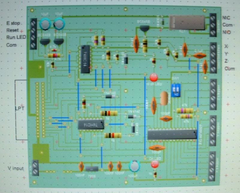
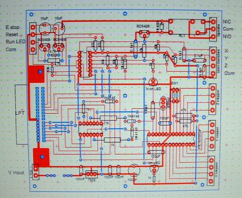
I’ve just set out my version of Chris’s diagram in Circuit Wizard but it seems I have made it look a bit complicated compared to Chris’s as it’s got 4 boards, unforchantly I didn’t see any of this post until today. I came across Chris’s work when searching Google and found his schematics then wend to work on it then found this thread.
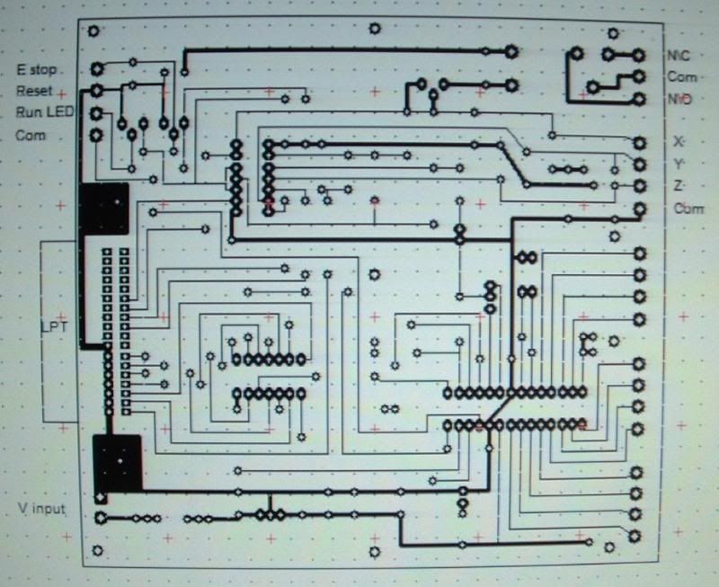
Anyway photo 1,2,3 shows the LPT control side of my layout all the same board jus that one is the component side 2 is the component and track side and 3 is just the tracks.
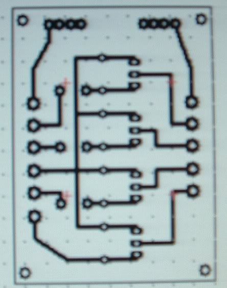
Photo 4 is the stepper motor driver board component and track side there’s 3 of these one for Y,Z,X.
Photo 5 is just the tracks.
I’ve almost finished the mechanics of my CNC and now got all the parts together for the electronics; PIC is programmed just got to etch the Boards now.
Maybe if there still any interest in the thread I my post photo’s of mechanics.
Just to let you all know I’ve just about given up on this project now, has I’ve had no reply from kiwichris regarding information needed before etching. I’ve sent about 10 emails to Chris through various websites and forums with no response.
Hi Phil,
Sorry about the lack of reply, hobbies got shunted well down the list for me over the last couple of years...
I'm getting back into it a bit lately, and I'm looking to build a larger/better CNC as well..
On your PCB's...
Good work laying it out, but if you had have built it I'd have concerns about putting the mosfet's off-board like that. Generally want the circuit/wire lengths for the powersupply caps to mostfet, and drive from the PIC to be as short as possible to avoid any issues with inductance/capacitance or resistive loss in the circuit.
Cheers, Chris H.
 Posting Permissions