


 Reply with Quote
Manofmanyhats:
Is it possible for me to move the thread to the DIY section?
Mcphill:
Thank you for the encouragement, and thank you for the suggestion. I have been just uploading straight to the website, but I've always used photobucket.com for image hosting, so I've put my images there for this message. Hopefully that works out better.
As for your planned build, I encourage YOU to start one and show us your journey too, I'd love to see you build the granite parts in particular. I spaced the bearings further apart on my X axis (left to right) and possibly made the gantry beam a bit more of a square cross section rather than that taller rectangle that mine currently is, so that's my advise to you - nice square beam and good spacing for the bearings if your machine will be tall like mine.
mkd:
Thanks man!
A_Camera:
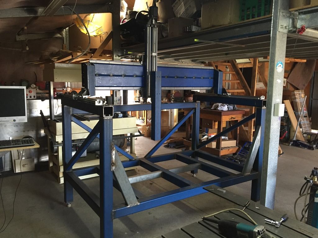
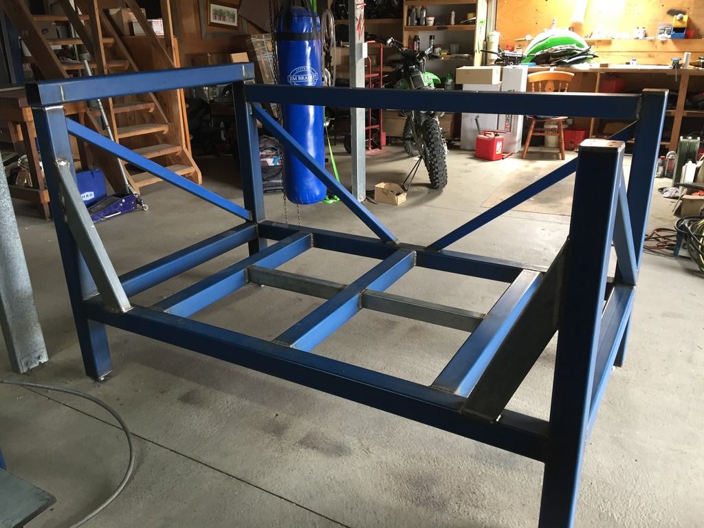
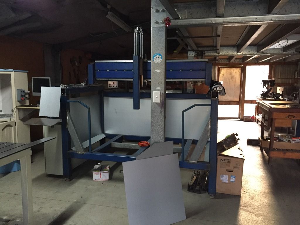
Here's some of the action from the last post to the state of the machine today. Latest at top, oldest at the bottom.
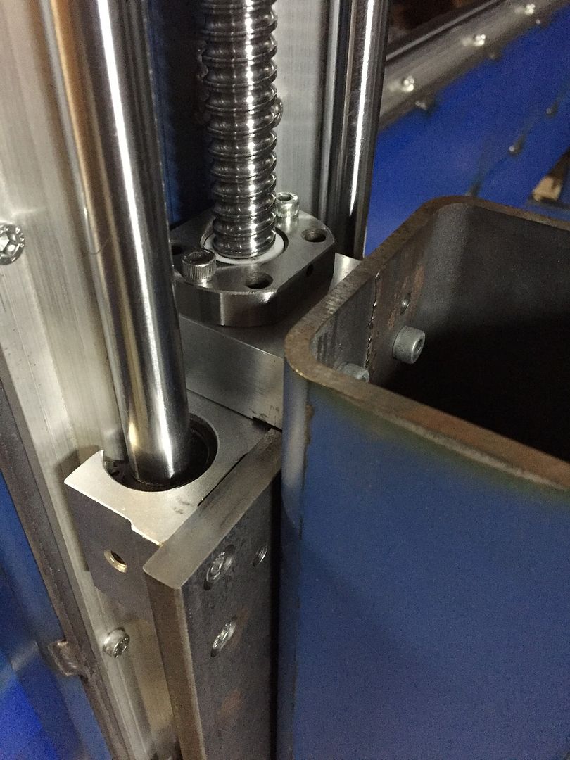
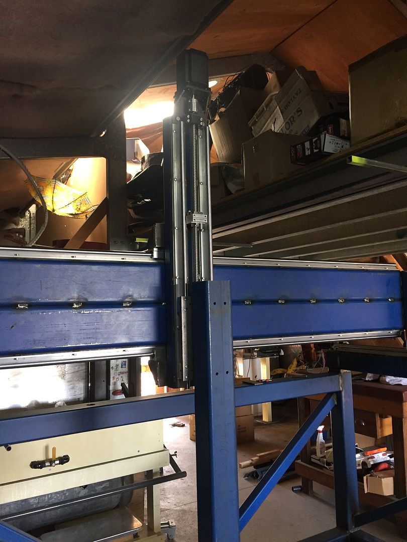
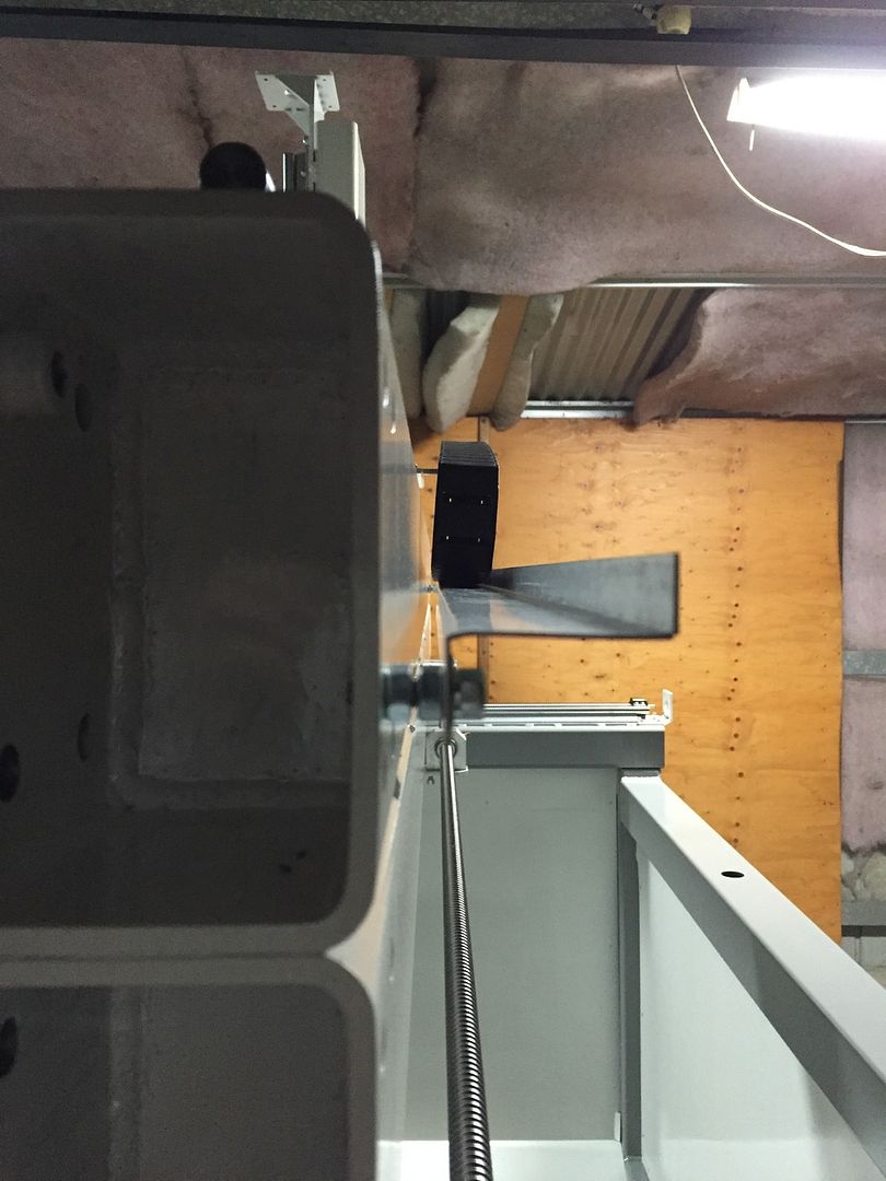
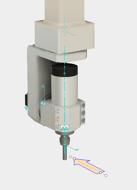
Z axis
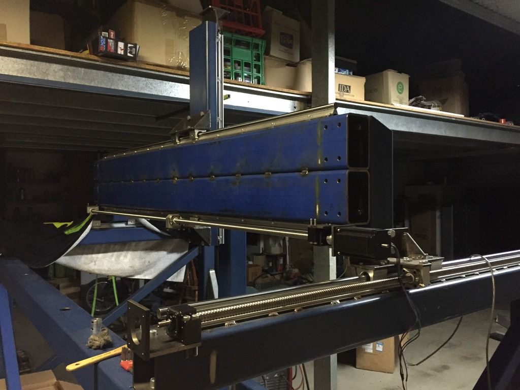
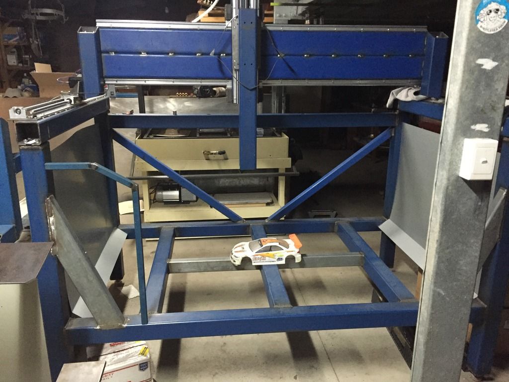
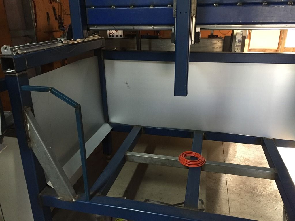
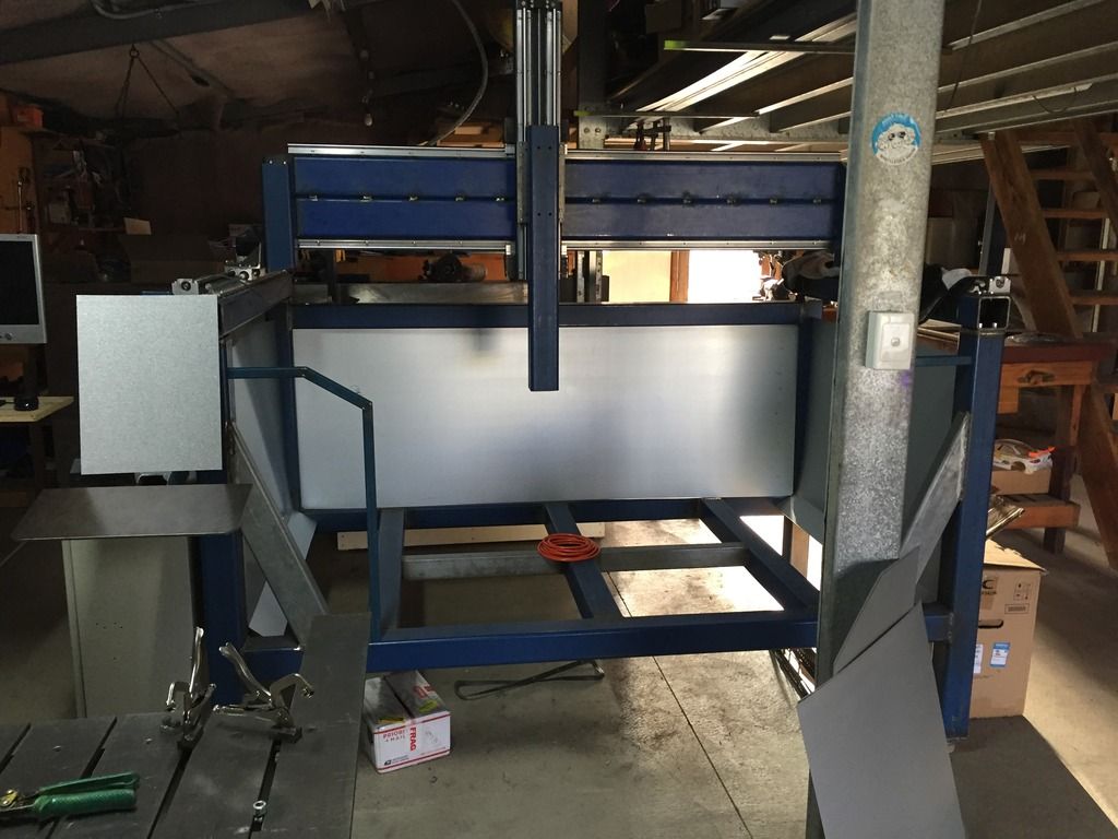
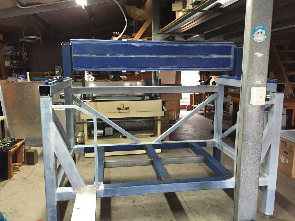
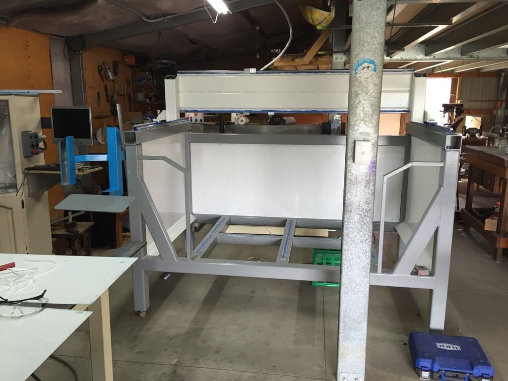
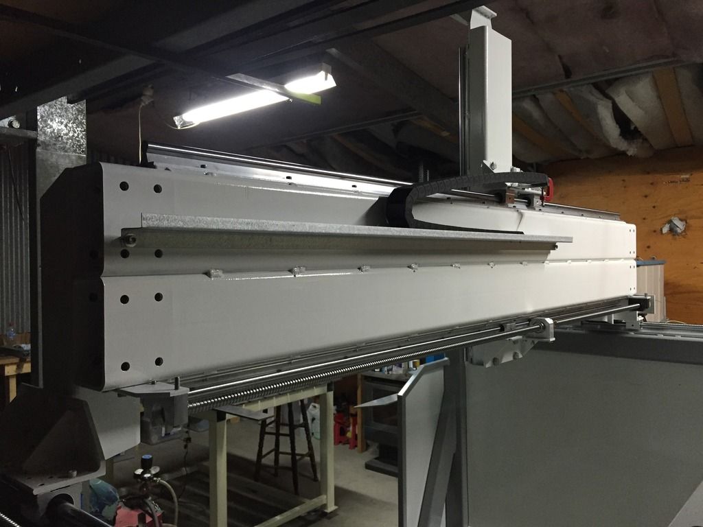
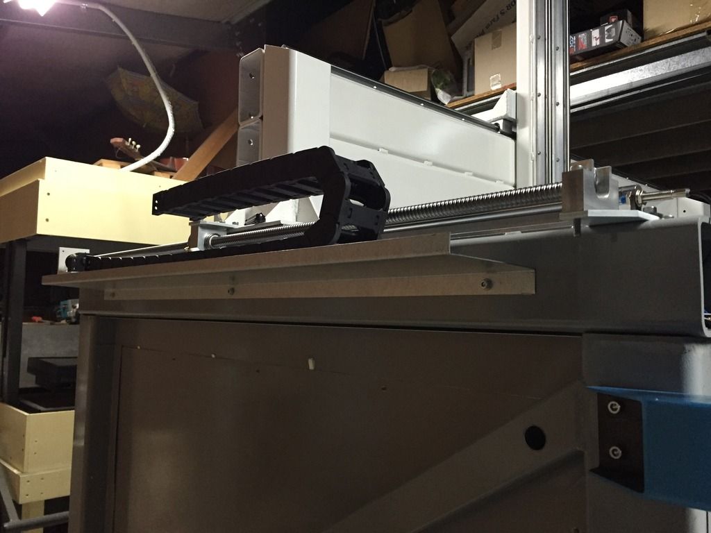
Back of machine
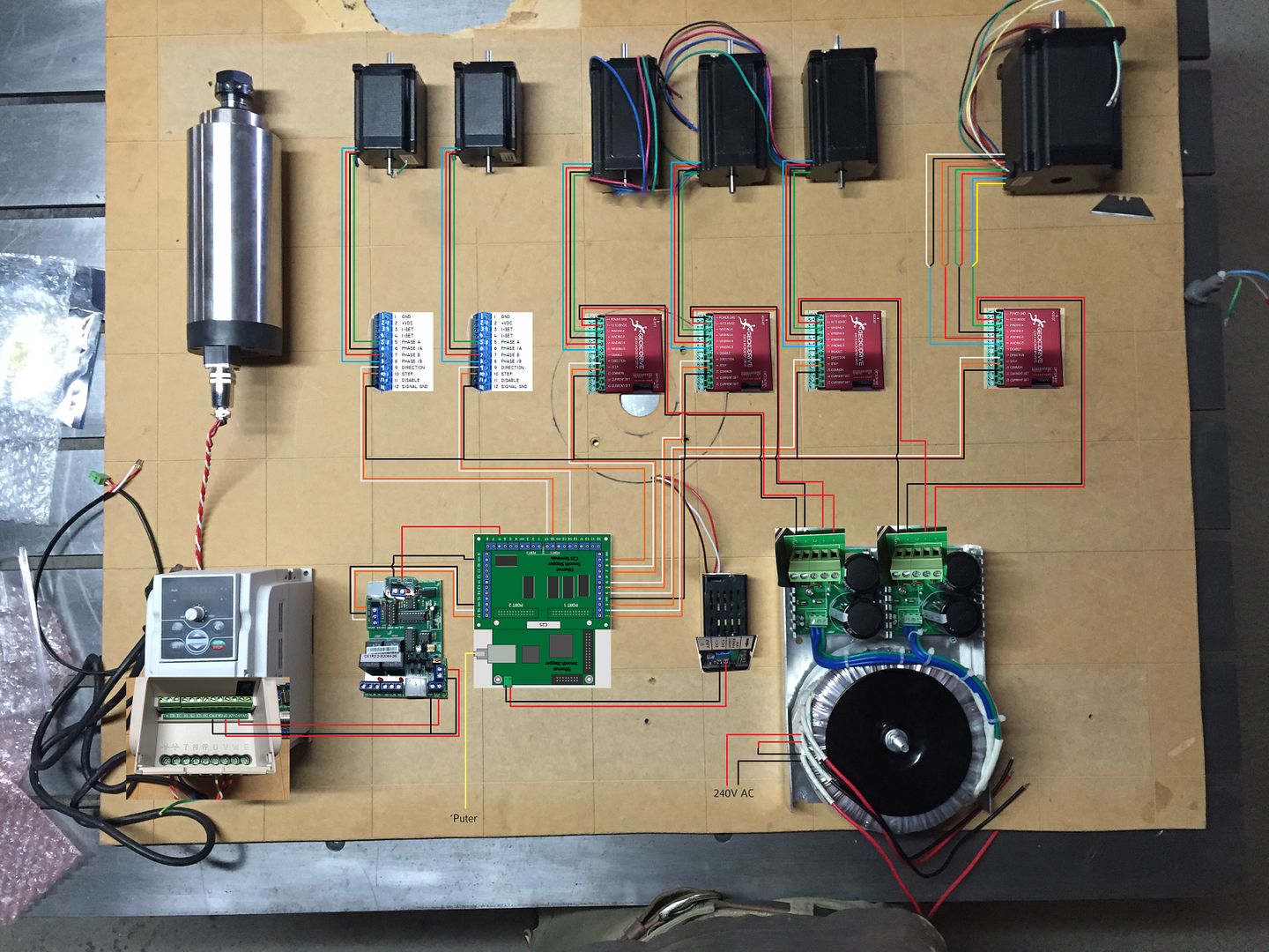
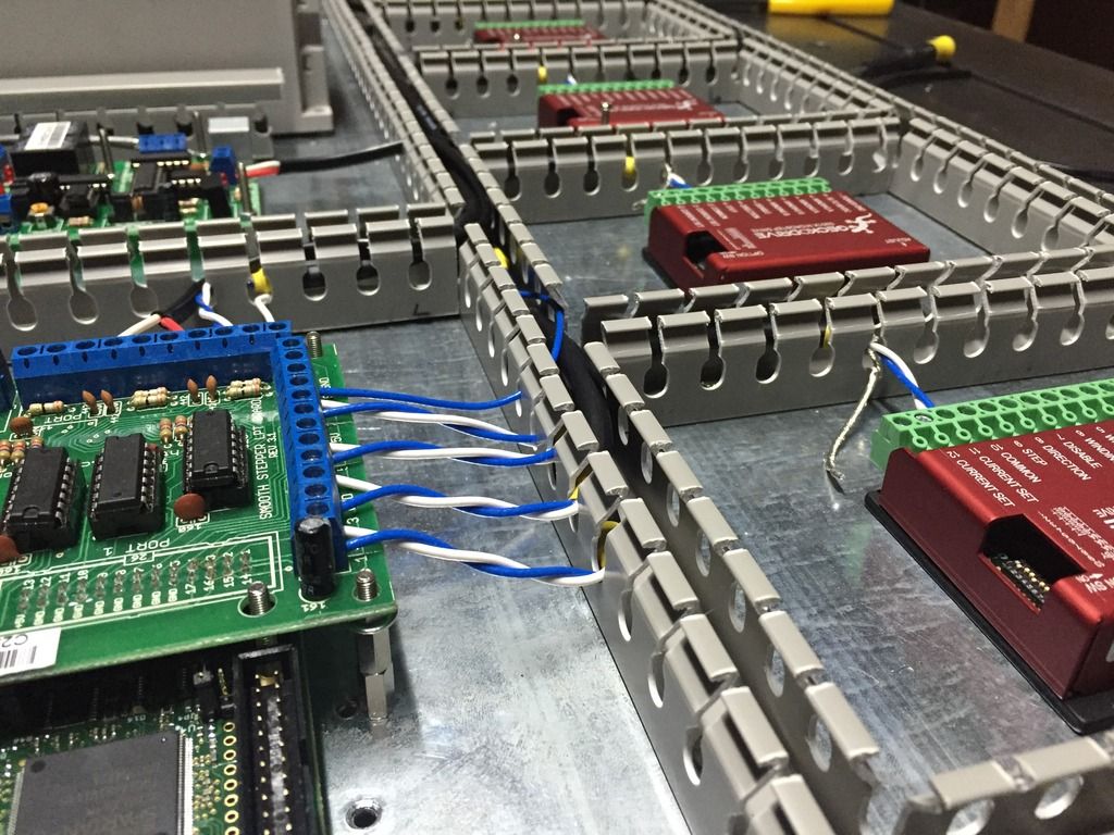
This is how I figure out the general wiring for testing - take a photo, then draw the wires with Photoshop (or any other image manipulation software).
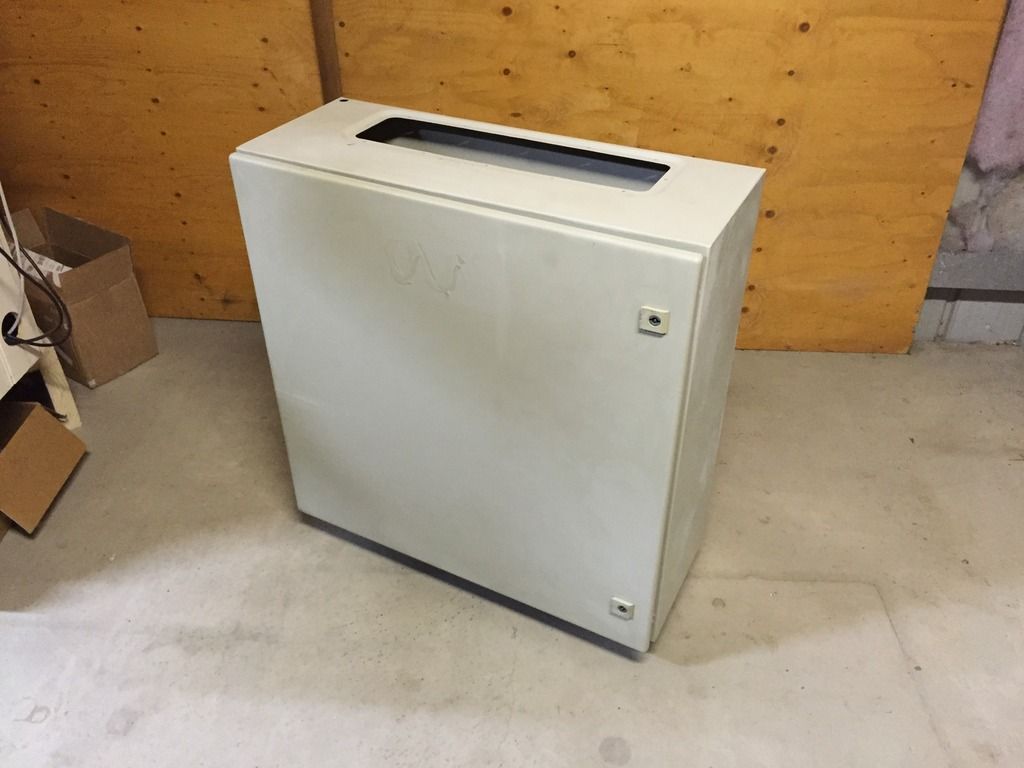
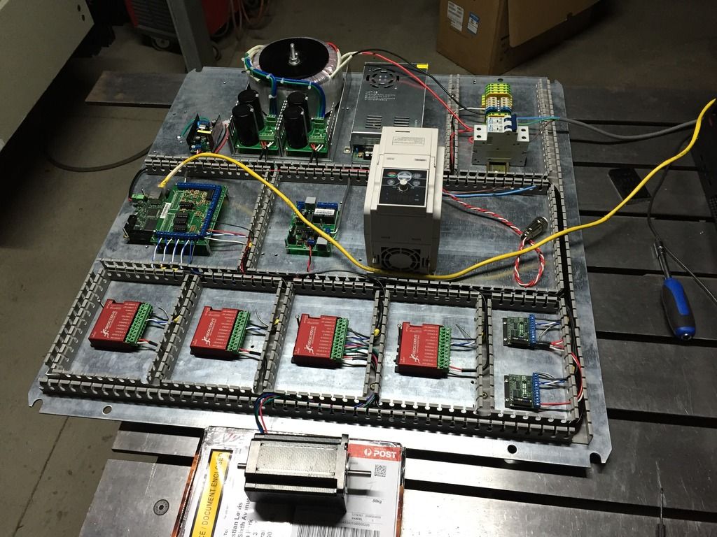
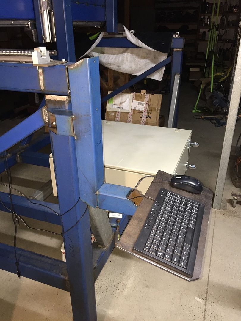
Electrical box with castors. This is detached from the machine frame to avoid the vibrations and all. The box is 760mm x 760mm x 310mm, it will contain all the electronics controller electronics and the PC in one neat unit.
The electrical panel.
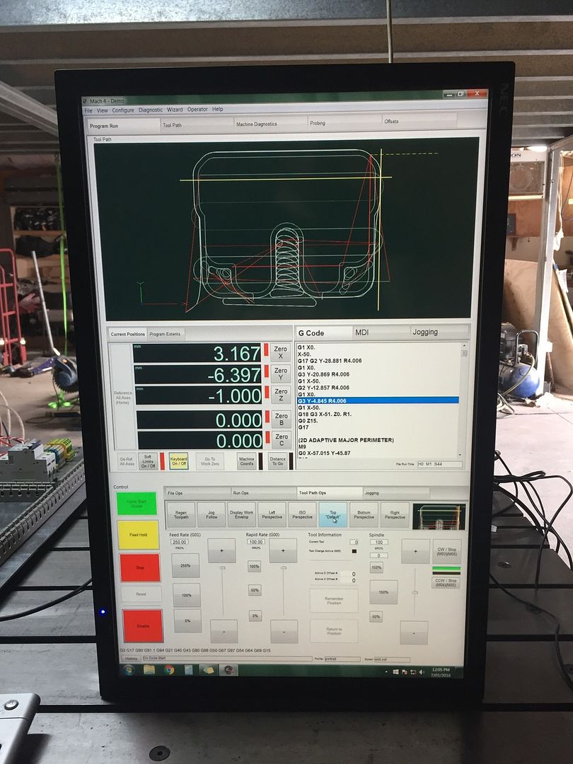
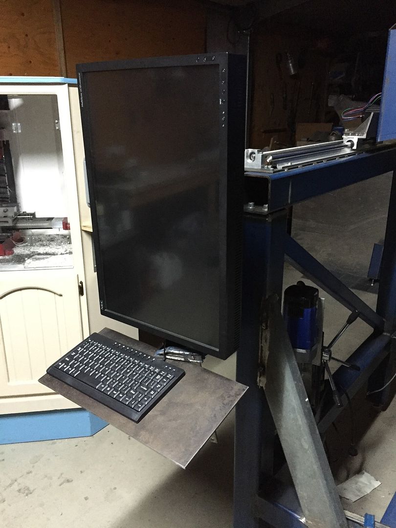
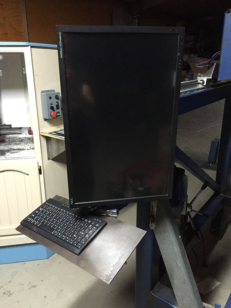
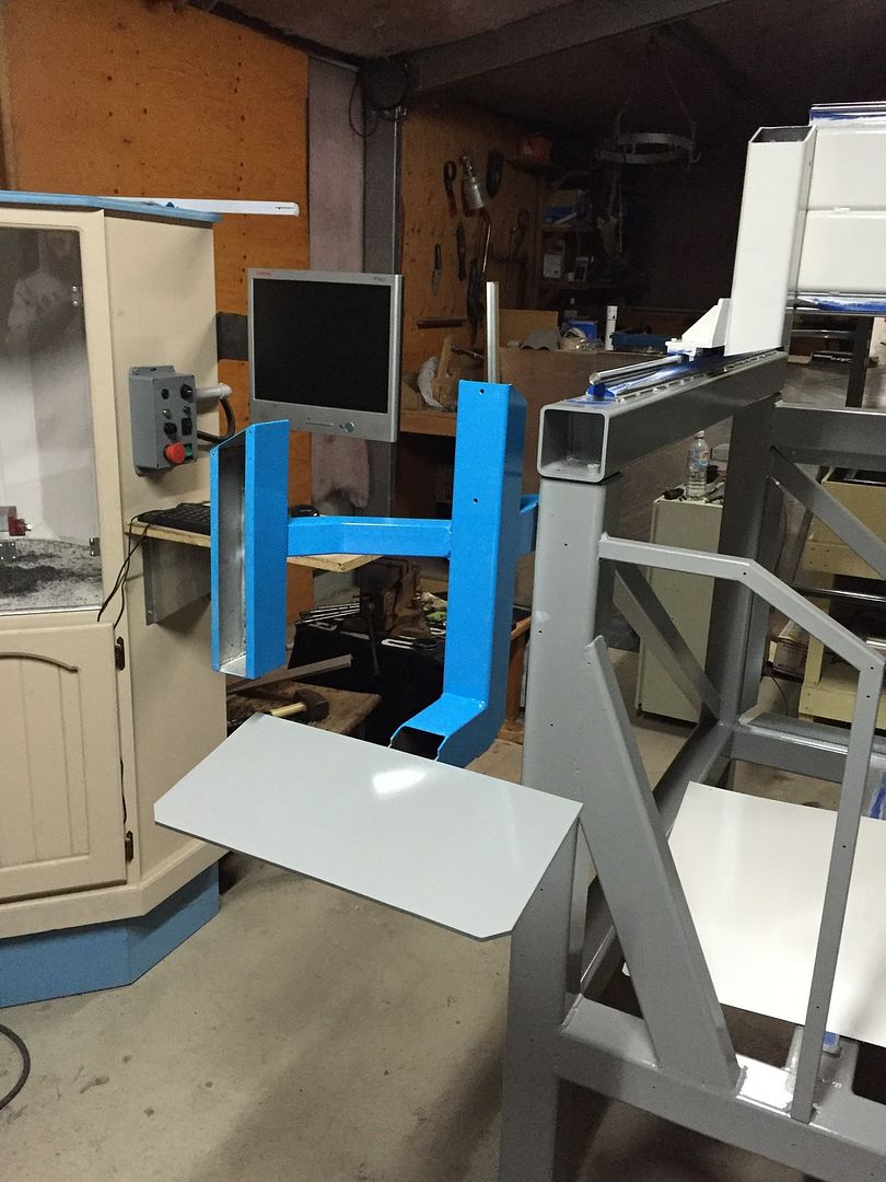
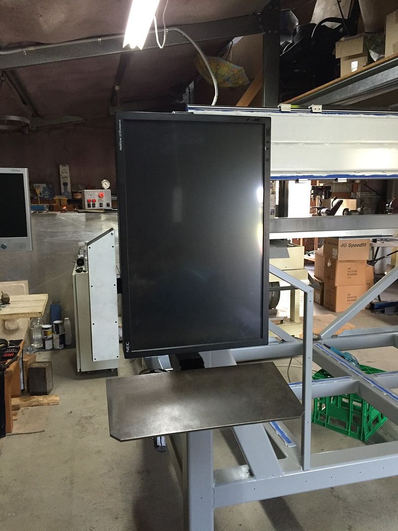
I managed to snag a nice big 24" NEC touch screen monitor for AUD$265 (USD$201). I've seen them brand new for over AUD$1000! I've completely rearranged all the Mach4 screens to suit a portrait orientation. Why? Because I can.
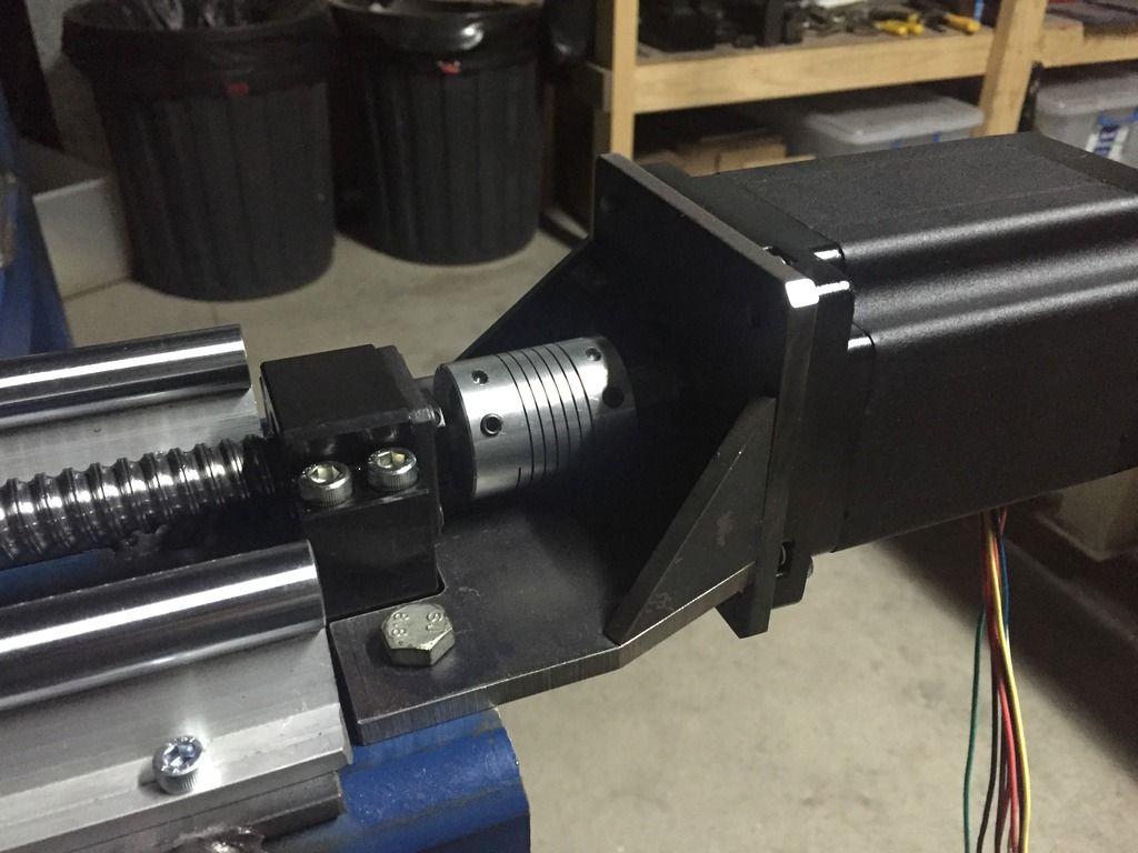
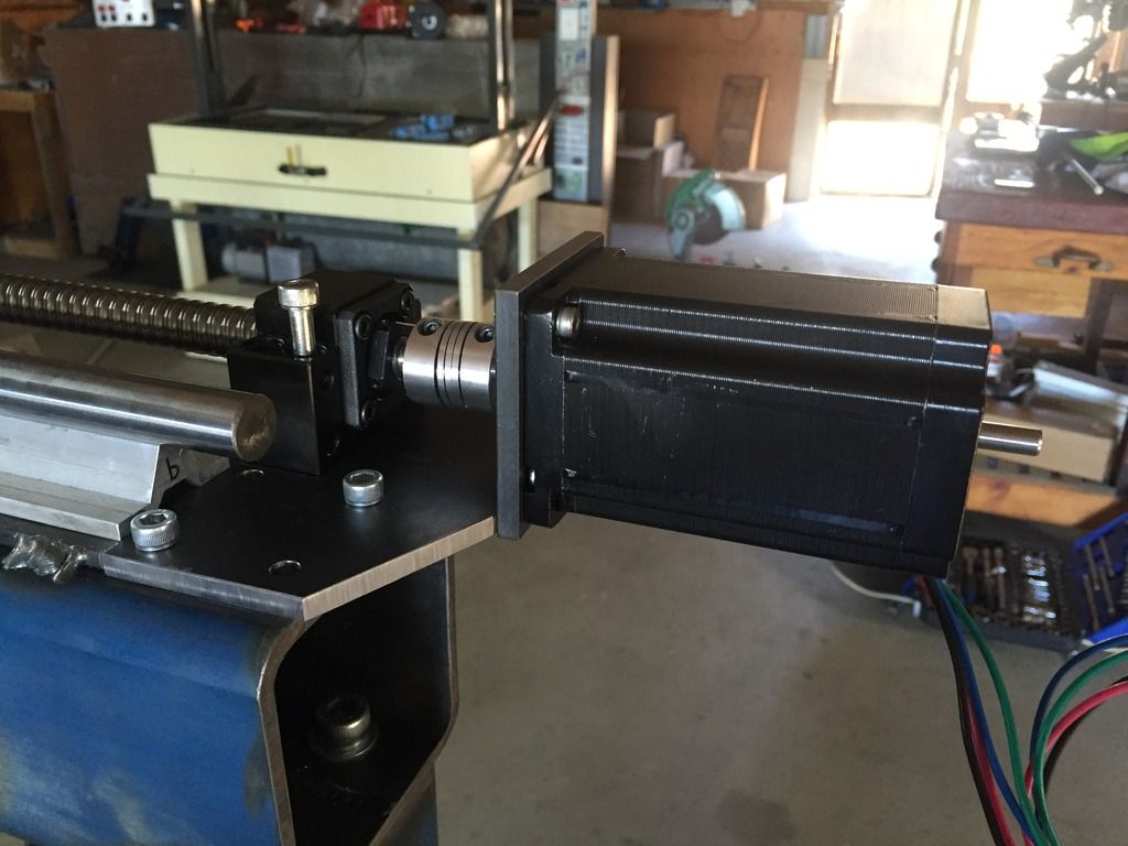
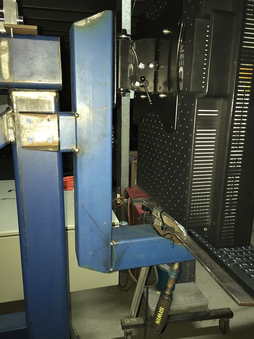
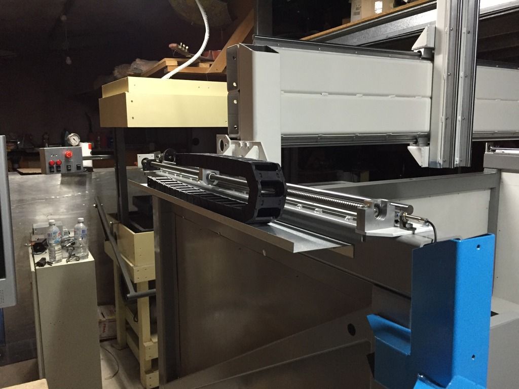
Z axis motor mounting.
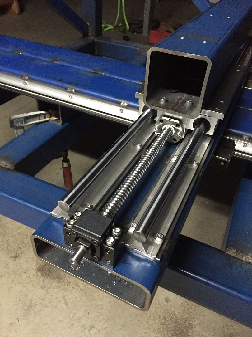
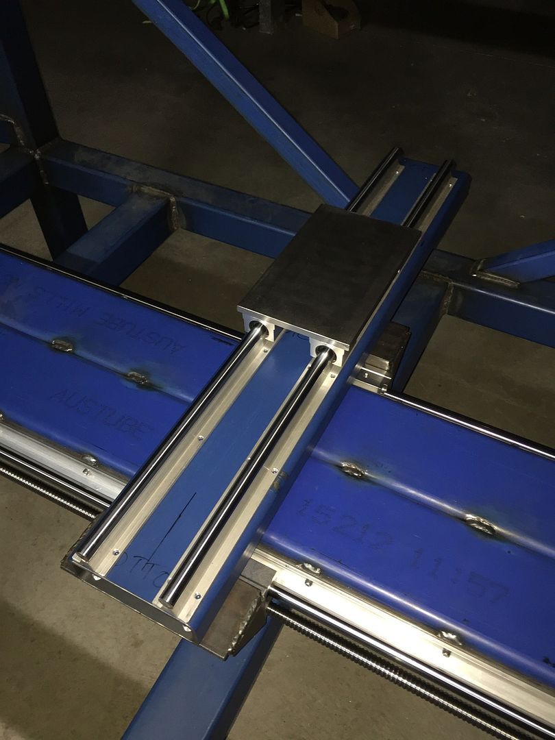
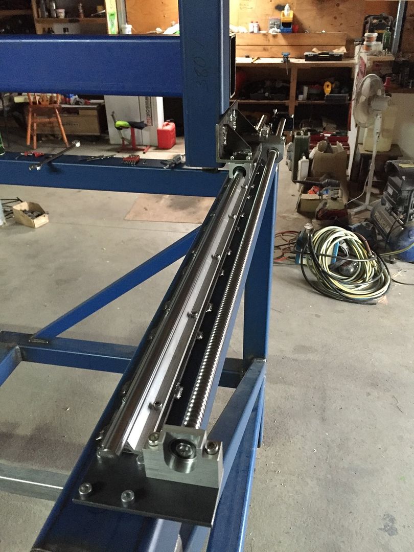
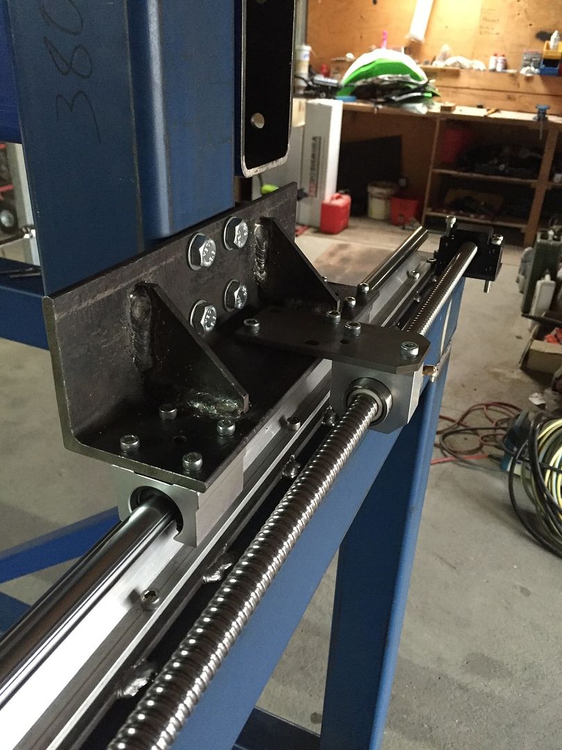
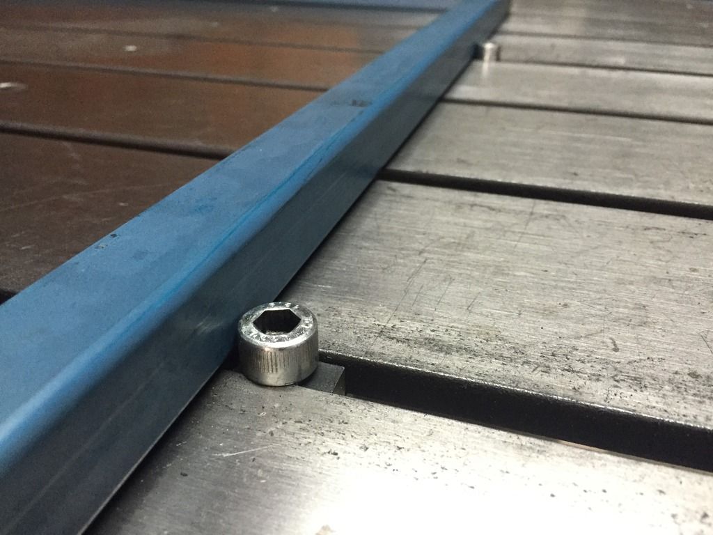
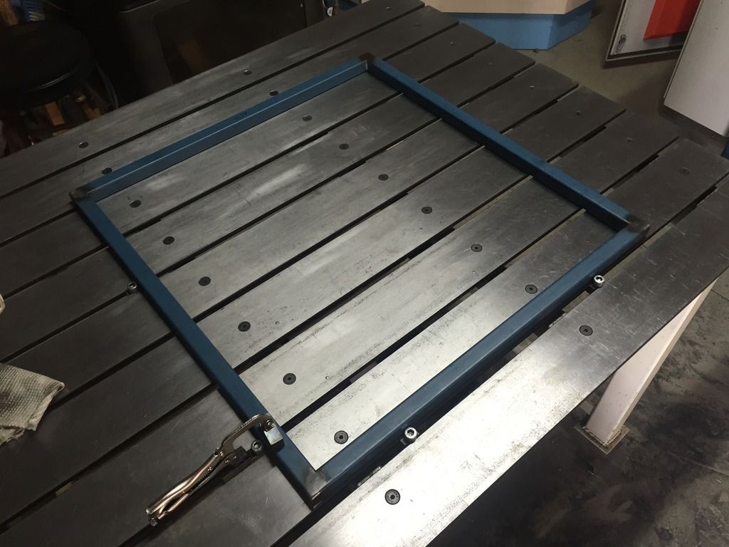
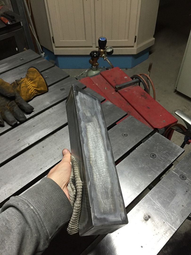
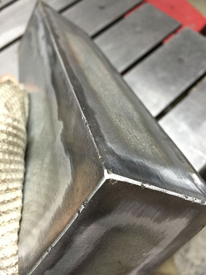
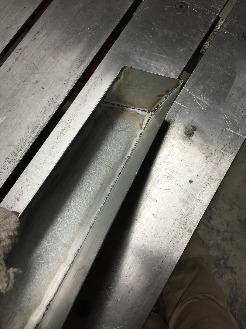
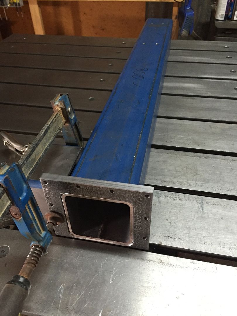
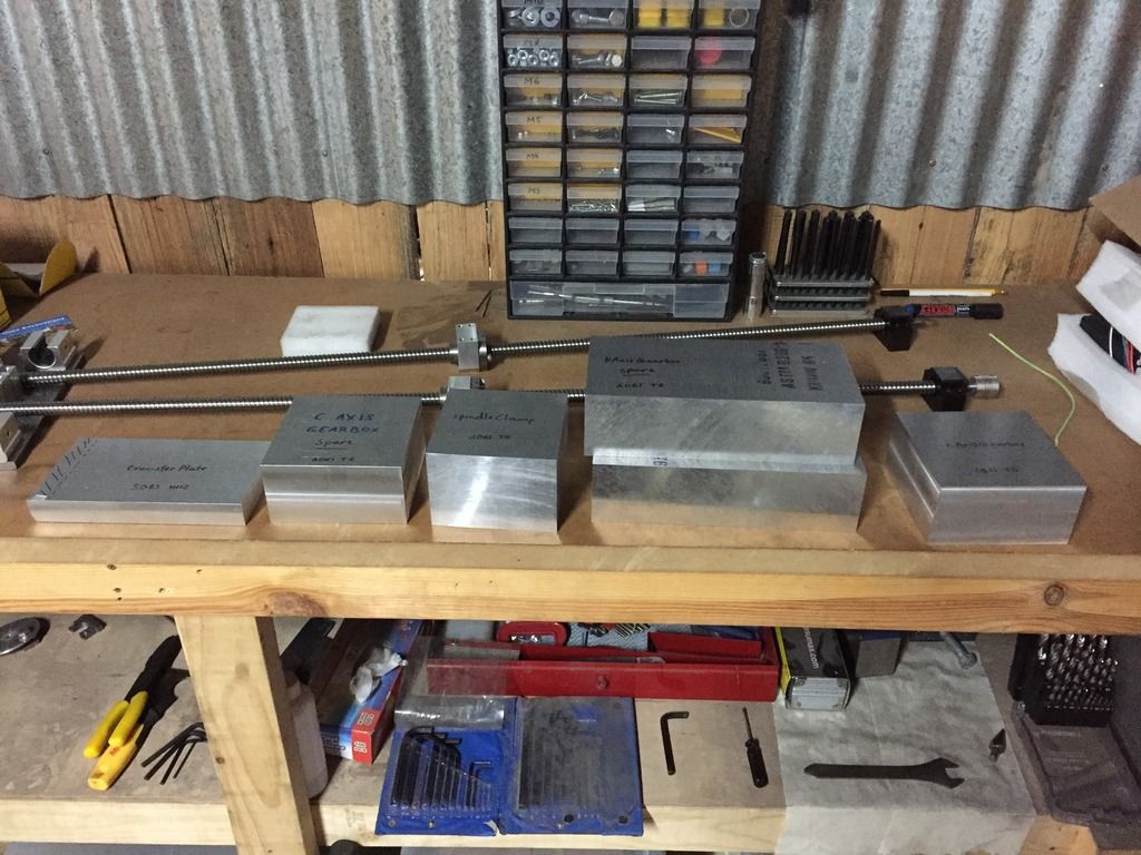
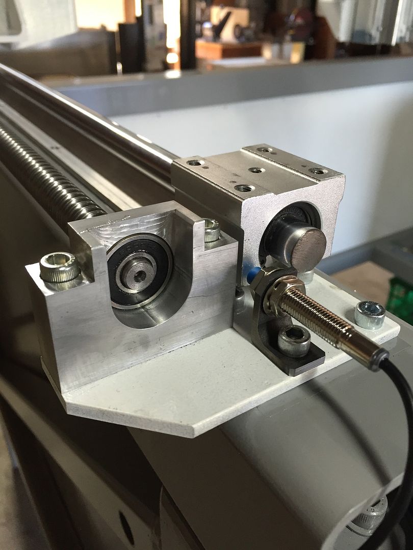
I had to remake the Y axis (forward and back) driven end ballscrew mounting plates. They are also thicker, I really don't like the way I've mounted the X and Y ballscrews, but I think it will work for a the materials I'll be cutting (plastics).
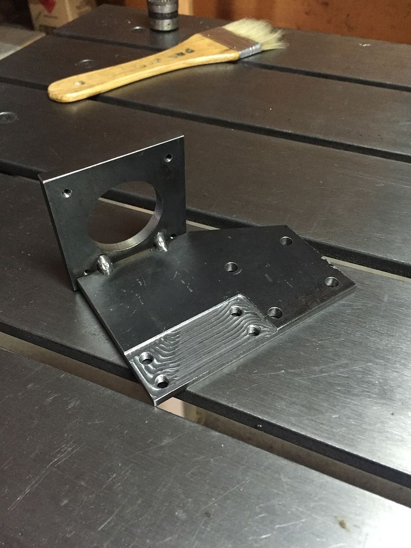
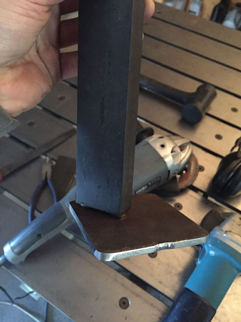
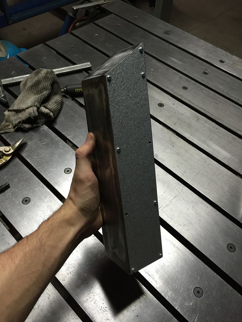
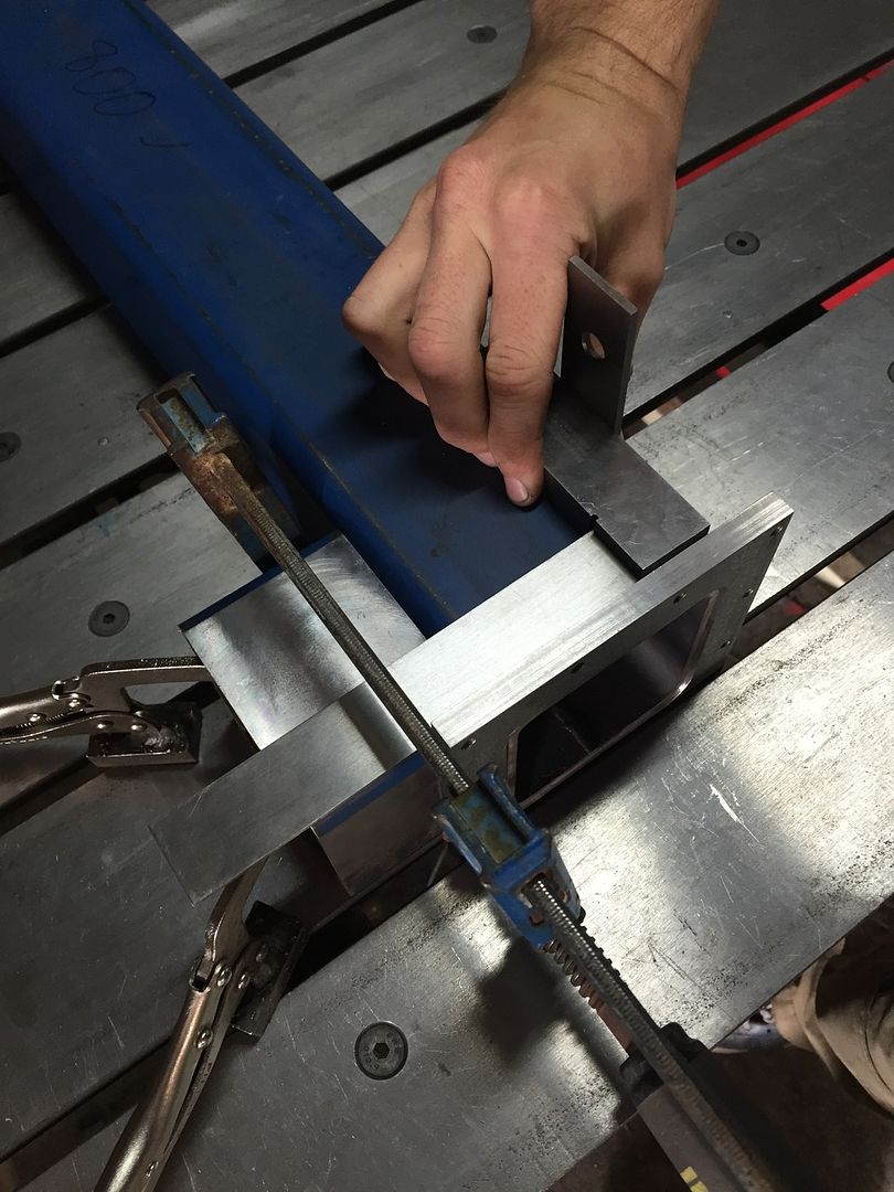
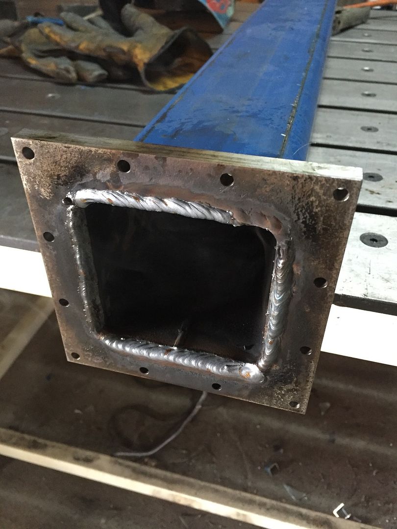
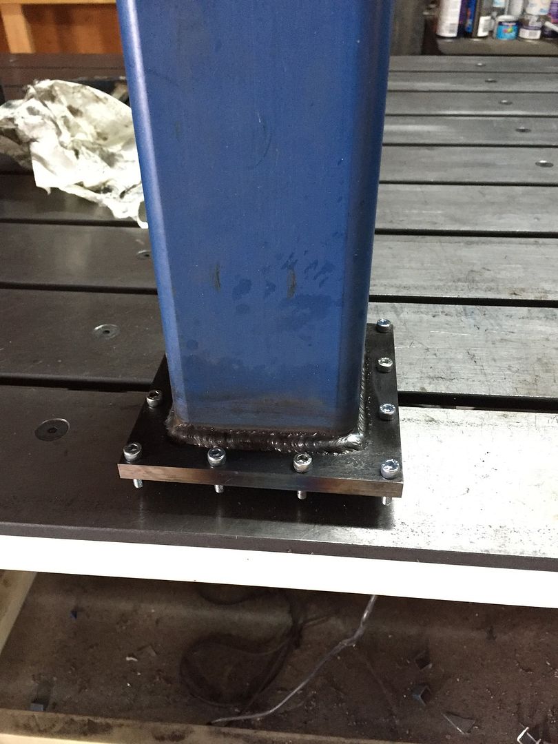
Hold the plate on the end of some flat bar with two small magnets...
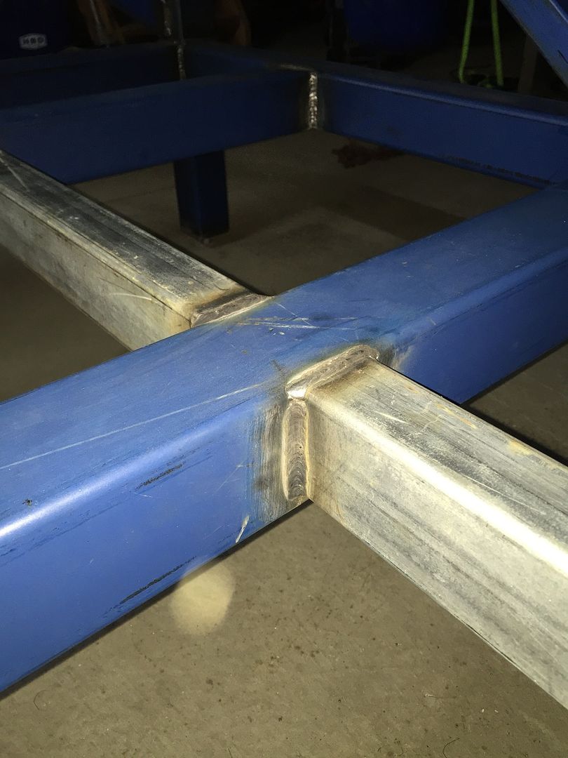
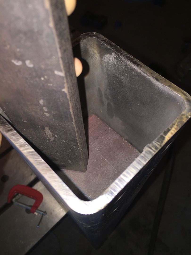
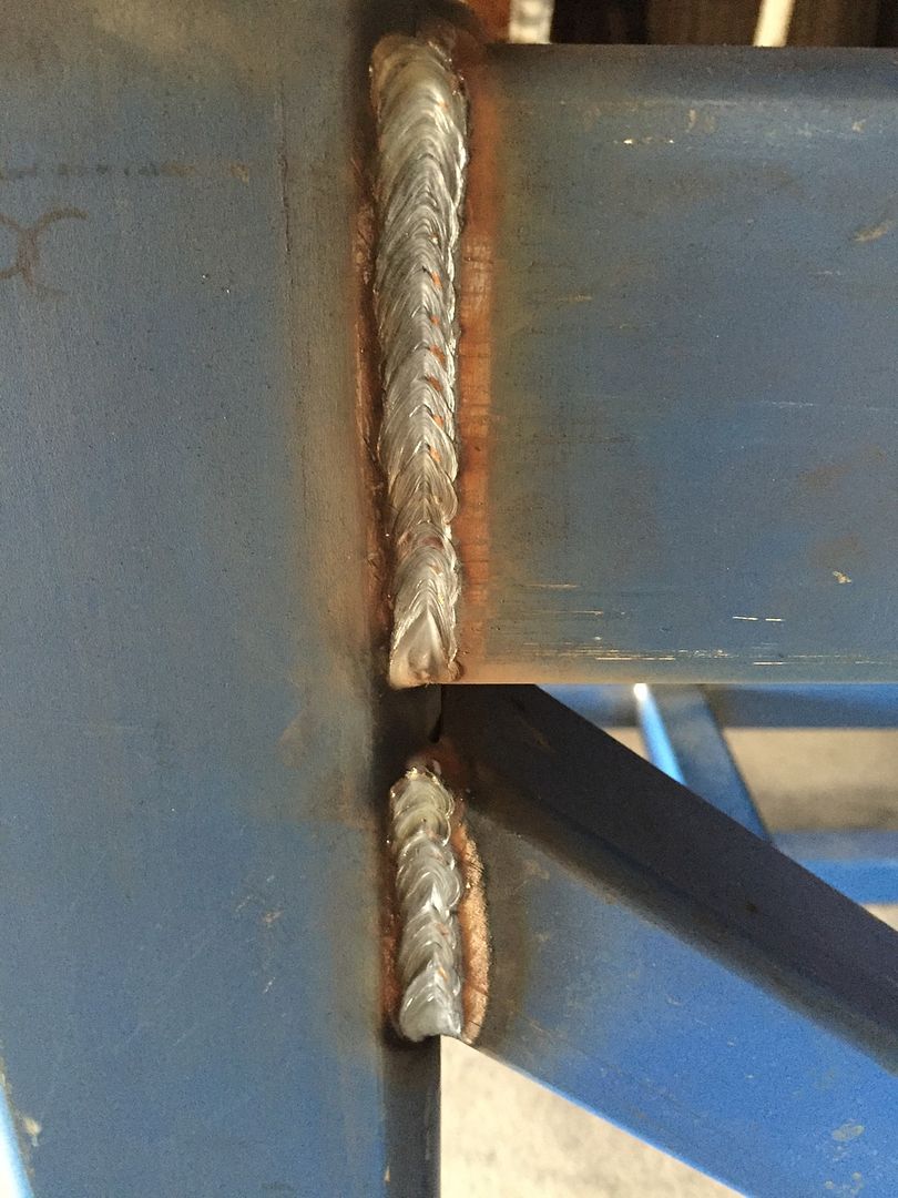
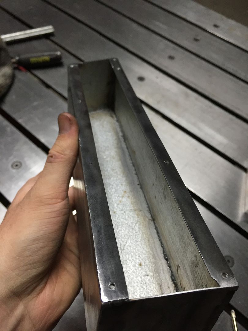
And weld inside tube for rigidity and to keep the sand inside.
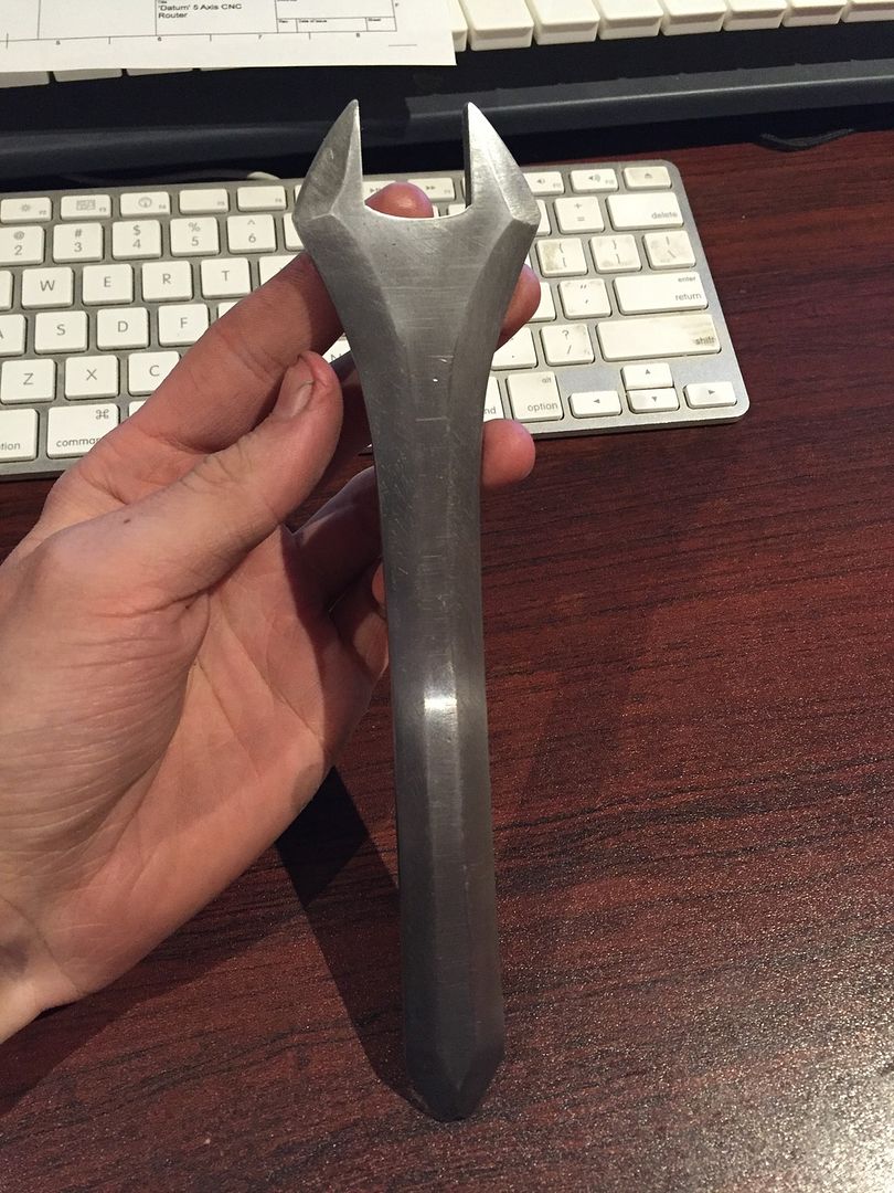
This was a bit of a side project where I needed a thin 17mm spanner to lock the spindle while I undo the collet chuck, so I take some time out to make this with basic tools only (not that I have many fancy tools anyway... Besides the CNC mill). I use an angle grinder to cut the basic shape out of the some 5mm x 50mm flat bar, then hand filed to finishing spec, and a nice 'old, handmade' look was the aim with some sanding to finish it off. Now I'm paranoid of it rusting, I should give it a lacquer coating.


 or is there a fridge nearby??? Gotta have a FROSTY ONE when tinkerin…!!!
