Reply with Quote
If I am going to make a first post it should be here in my mills build thread. Cannot wait to get started.


A buddy of mine is getting a BF20 clone from Busy Bee (Canada) and asked me to help him with the conversion. I already have converted my X2 and based on that experience and the size difference between the two mills I came up with the following recommendations for him. I might be going a bit overboard on the X and Y axis steppers (bigger is not always better) but I think the Z axis stepper needs to rather beefy as the plan is to use the original acme lead screws, to begin with anyway. I hope to have the mill in house this weekend and will post pictures as soon as possible.
I know Hoss and maybe others are starting a similar project so I was hoping to get some feedback on this.
Mill
http://busybeetools.ca/cgi-bin/picture10?NTITEM=CT129N
Brake-out board $109
http://www.cnc4pc.com/Store/osc/prod...products_id=46
3 G201 Stepper Controllers
http://www.geckodrive.com/product.aspx?c=3&i=14458, 3*$114 = $342
Z axis stepper, Nema 34 960 oz/in Stepper Motor Model #RS34-960 $129.00
X and Y steppers, Nema 23 570 oz/in Stepper Motor Model #RS23-570, 2*$73 = $146
http://homeshopcnc.com/RSstepperMotors2.html
Power Supply, KL- 7212 Unregulated Power Supply 864W, 72VDC/12A, $149
http://www.kelinginc.net/SwitchingPowerSupply.html
Thanks for stopping by,
EK
Similar Threads:
If I am going to make a first post it should be here in my mills build thread. Cannot wait to get started.
Guess what I got in my garage... I wish it was mine.
Got some cleaning to do and then start designing the motor mounts and make some chips. Cant wait to see this one CNC'd
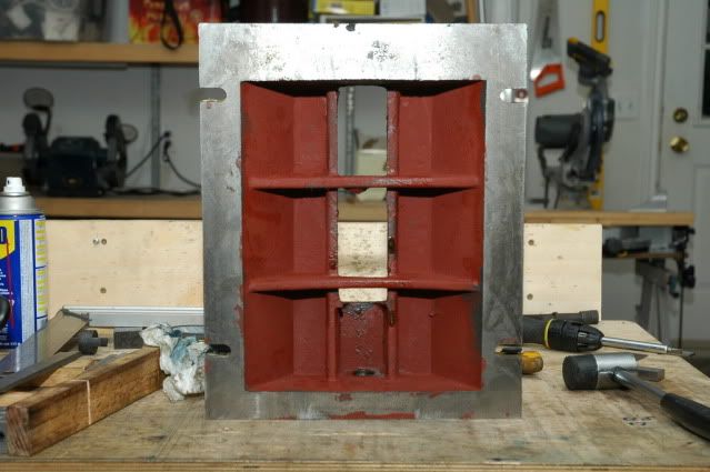
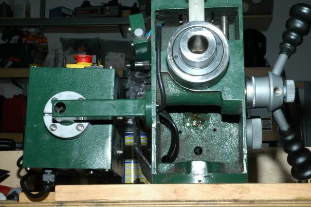
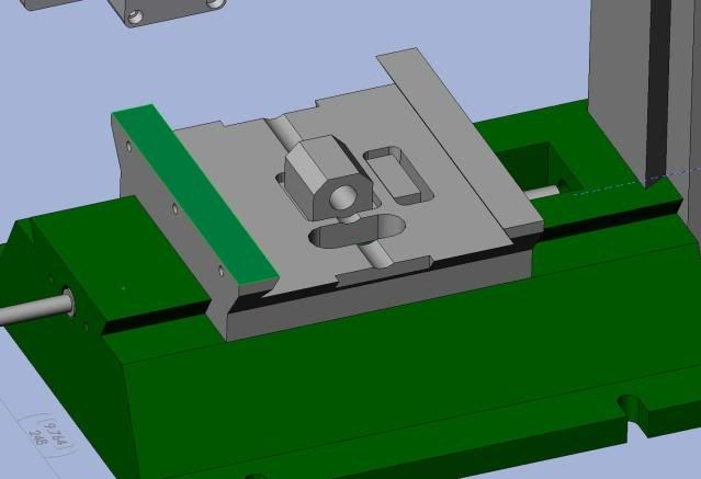
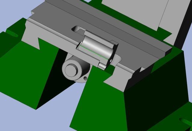
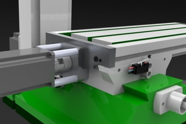
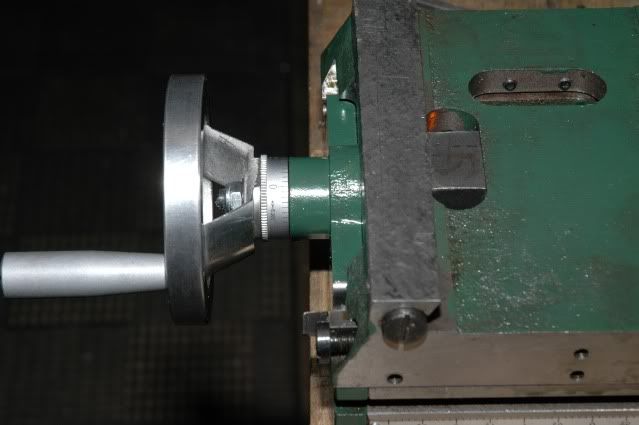
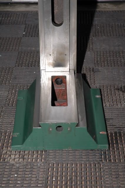
The Saddle is very low profile, it might prove difficult to fit a ballnut in there. Notice the tapered gibs...
Compare the table size and finish difference between the BF20 and X2...
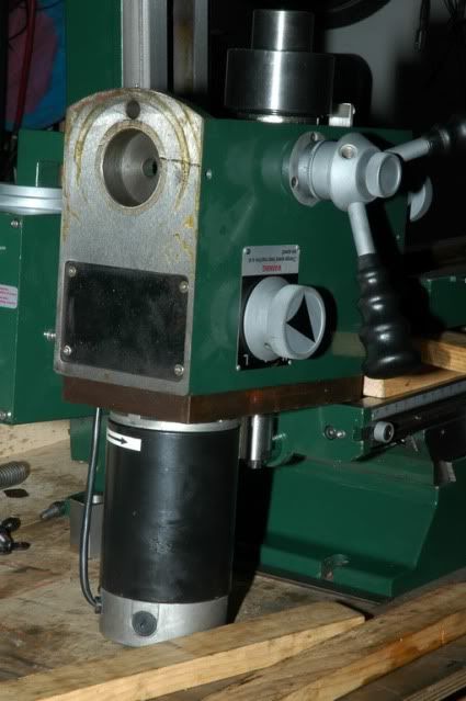
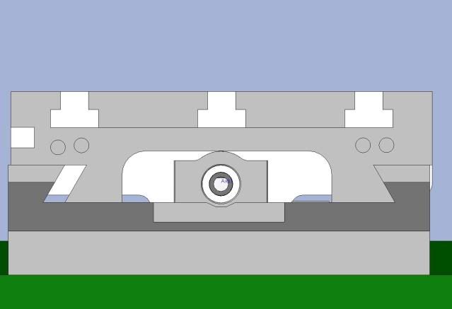
I spent the weekend cleaning and taking measurements for modeling. Here is a little preview.
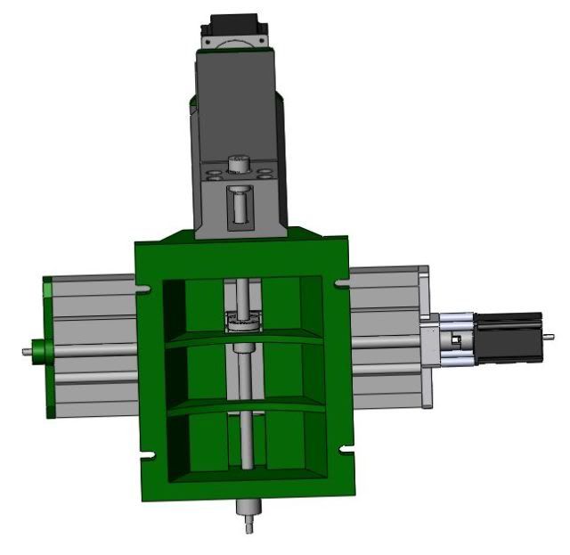
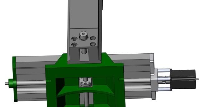
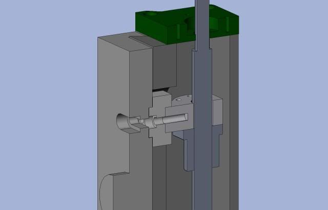
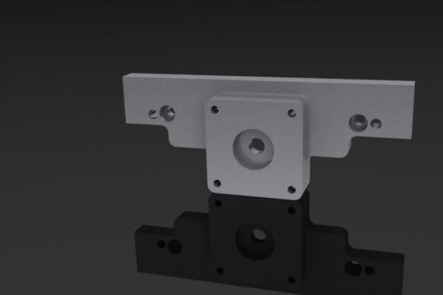
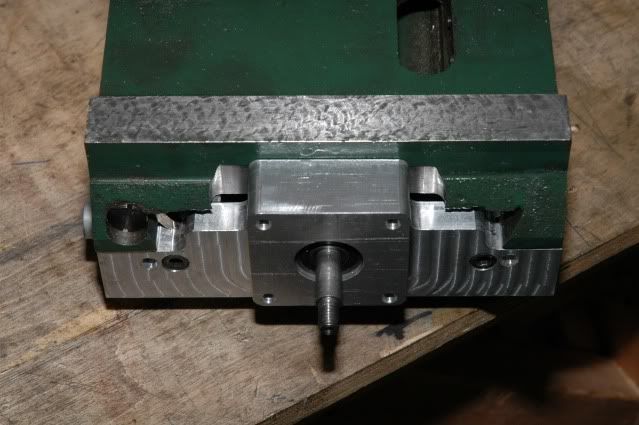
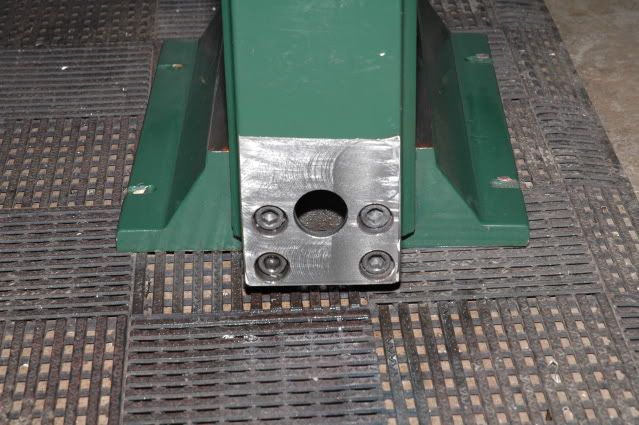
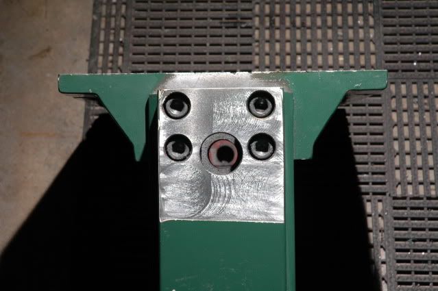
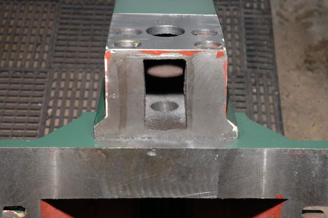
I have decide to go ahead and replace all three axis with ballscrews and mount the y axis stepper in the rear. I figure in the long run it will serve me better this way.
ellik's cad drawings of the rear mounted stepper setup
Parts were dropped off today to get machined for the rear stepper and ballscrews have been ordered.
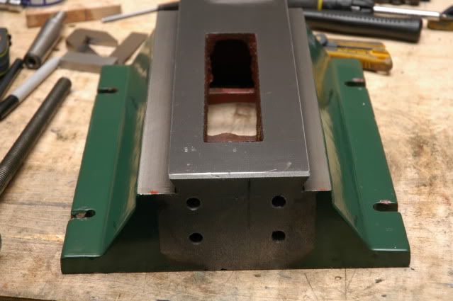
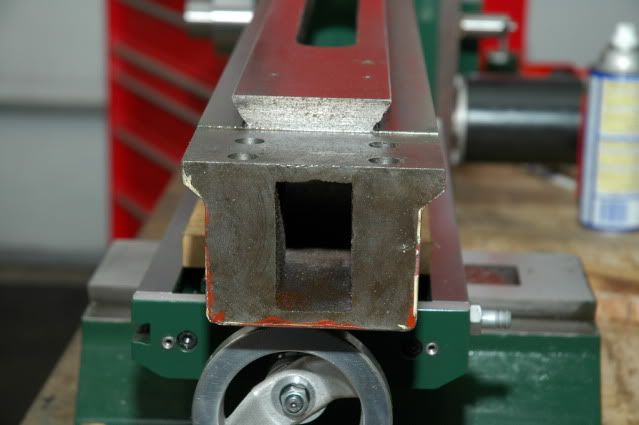
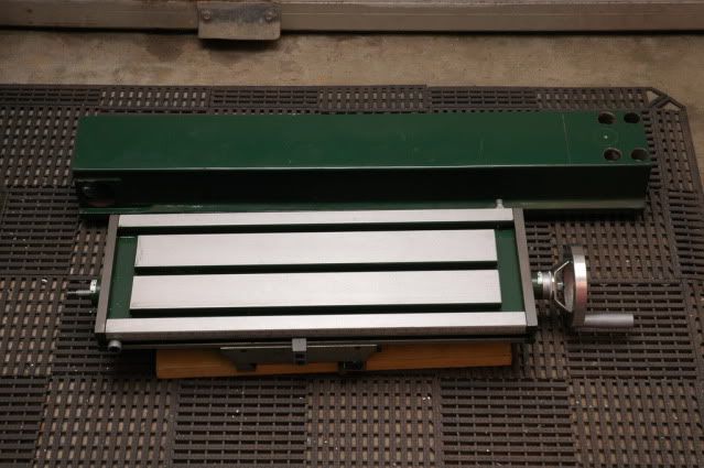
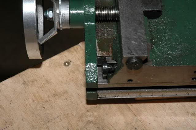
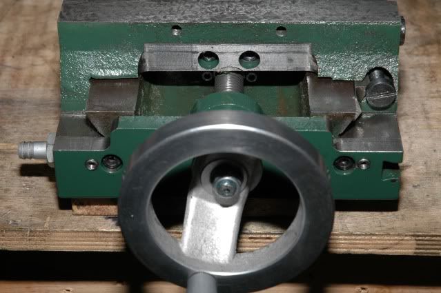
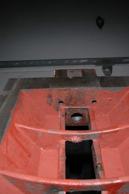
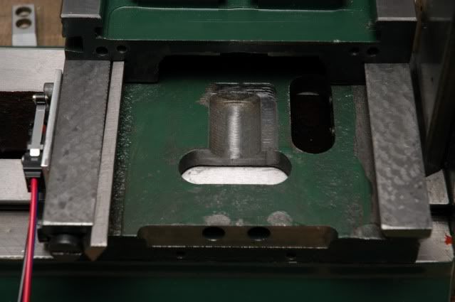
Here are a few pics of the tear down.
A few solidworks drawings
Looking good, teamwork yeah.
I figured the rear mounted Y stepper would be pretty easy, will look more like a VMC too.
Hoss
Gosh, you've... really got some nice toys here. - Roy Batty -- [URL]http://www.g0704.com[/URL]
That base wants to be filled with epoxy/granite. You know it does!
Cheers,
BW
Try G-Wizard Machinist's Calculator for free:
http://www.cnccookbook.com/CCGWizard.html
I really wish I lived closer or this would be a group build but a ocean and a 1000 or so kilometers makes it a little difficult to work on this together.
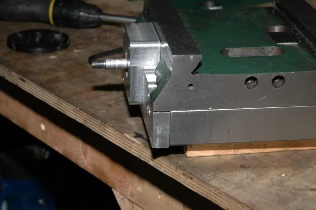
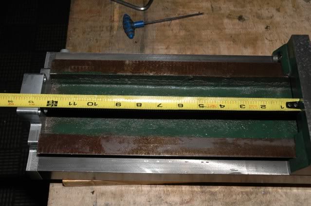
Ellik made a few modification to the X-axis to increase travel from 11" to 12 5/8".
my 0704 is on order. so i am following this like a hawk.....
Column and base back from milling. Ballscrews are ordered and should be here in the next two weeks I hope. The steppers are still not ordered but then again I am not 100% sure what to get. Many options but I want something that will do the job and won't have to be replaced and time soon. I would rather get it right the first time around.
Looks nice, I was having problems figuring my setup also. Mr. Keling called me this morning, nice guy, and I decided to overlay the torque curves. Does this help anyone else?
This may get people wondering if they are running their steppers too fast....
His charts are helpful. I cant see on that chart but some of the others on his his site have the steppers running in series or with a 100V or 60V driver so you do need to look closely at the charts.
With steppers its all about the inductance. With a GECKO drive you only have 80V and 7A so if you want 500 RPM for a direct drive setup any stepper with less than about 4MH should work fine.
He has a nice looking Nema 23 with a 3/8 shaft and 570 oz/in that just books at 75V and 5A. It would run the table just fine. The nice thing here is it is small around so in a direct drive setup it should be lower than the table in case you ever try to put some long stock on the table. This is it. KL23H2100-50-4B.
I have this motor and am testing it for my BF-30 project and it is what I will be using.
I don't really like most of his Nema 34's because he need to have higher current models for the Z but the 900OZ should work OK with a belt drive. I'm going to run a servo for the Z at about the same price.
I'll concur, I plan on the 570's at 5 Amps for the X and Y and a 906 (743@5A) on the Z.
Hoss
Gosh, you've... really got some nice toys here. - Roy Batty -- [URL]http://www.g0704.com[/URL]
All right, thanks for the input. I was going to go with the 1200's for all three axis. that is going to be overkill then, I will go with the lighter setup. Are you putting ballscrews in? If you order them cut, would you posts from where? I have to have mine cut likewise, I dont know if you decrease the charge for cutting two sets...but it may be worth looking into.
Is it rude to ask if I can use the measurements, and or the 3d files that someone else made? I am not sure about the etiquette for this kind of question. I would like to get familiar before mine arrives.
Last edited by mattbesquare; 02-10-2010 at 12:01 PM.
Ballscrews all the way for me but I cut my own.
Hoss
Gosh, you've... really got some nice toys here. - Roy Batty -- [URL]http://www.g0704.com[/URL]
ellik and sfrankland nice Job!
I can't wait for my Grizzly 0704 to come in...
Rob
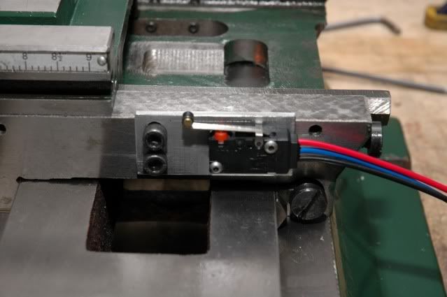
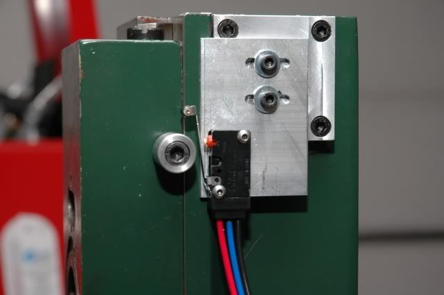
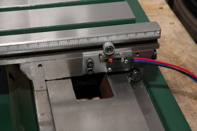
Limit switches mounted up.
I am going with ballscrews on all three axis. We ordered the ballscrews from eBay seller linearmotionbearings2008.
http://cgi.ebay.ca/3-Anti-bachlash-b...item3a55b29f88
I don't have the exact measurements but this is what we ordered and the prices.
RM1605-470/567mm(2screws+2ballnuts):
88.00usd
RM2005-580mm with a ballnut:
49.00usd
End machinings for these 3 screws:
21.00usd
As for the CAD drawings you will have to ask ellik as he is the one who created them.