Build Thread Graham's Optimum BF20 Build - Page 5


Page 5 of 10 FirstFirst ... 2345678 ... LastLast
Results 81 to 100 of 193

Thread: Graham's Optimum BF20 Build

  1. #81
    Member arizonavideo's Avatar
    Join Date
    May 2008
    Location
    USA
    Posts
    1185
    Downloads
    0
    Uploads
    0

    Default Re: Graham's Optimum BF20 Build

    Steppers are not constant current devices. In fact they will almost never run at 6A. The current number is a average over time. The instantaneous back EMF wave will make a much larger current spike depending on load but at any RPM over about 100 the current will be much less.

    The wire is large enough but the thinner wire will create more RFI than thicker wire because of the power dissipated in the wire. I would guess the wire will get a bit warm when being used.

    youtube videos of the G0704 under the name arizonavideo99


  2. #82
    Registered
    Join Date
    Nov 2012
    Location
    United States
    Posts
    220
    Downloads
    0
    Uploads
    0

    Default Re: Graham's Optimum BF20 Build

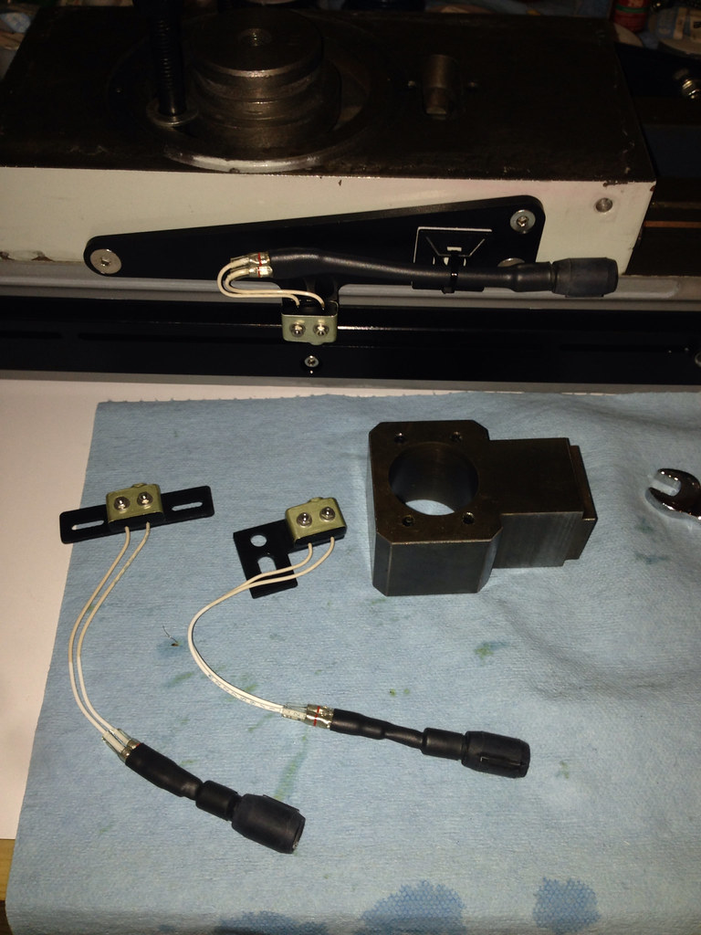
    Arizona, thanks for the feedback; I switched to 16 AWG wire on the NEMA 34 Stepper on the Z-Axis. Also, thanks alex_ku for the tip about the gas shock, you were right, so I flipped it around.

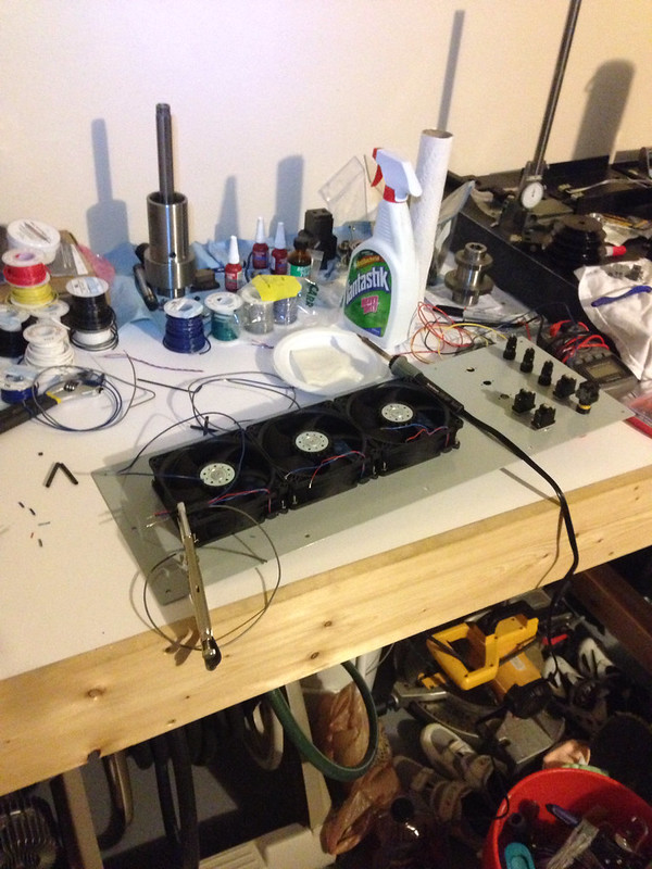
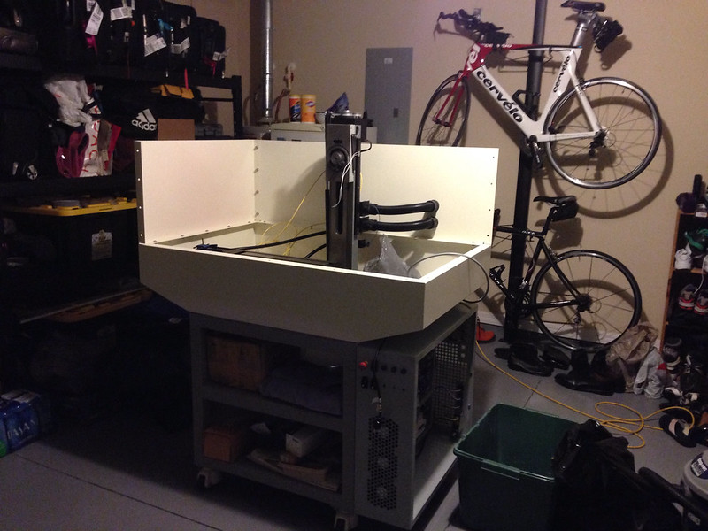
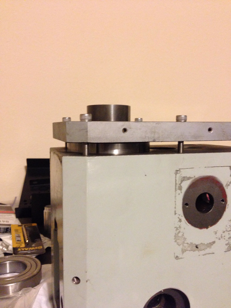
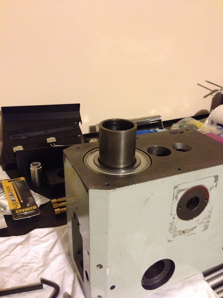
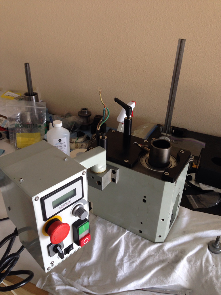
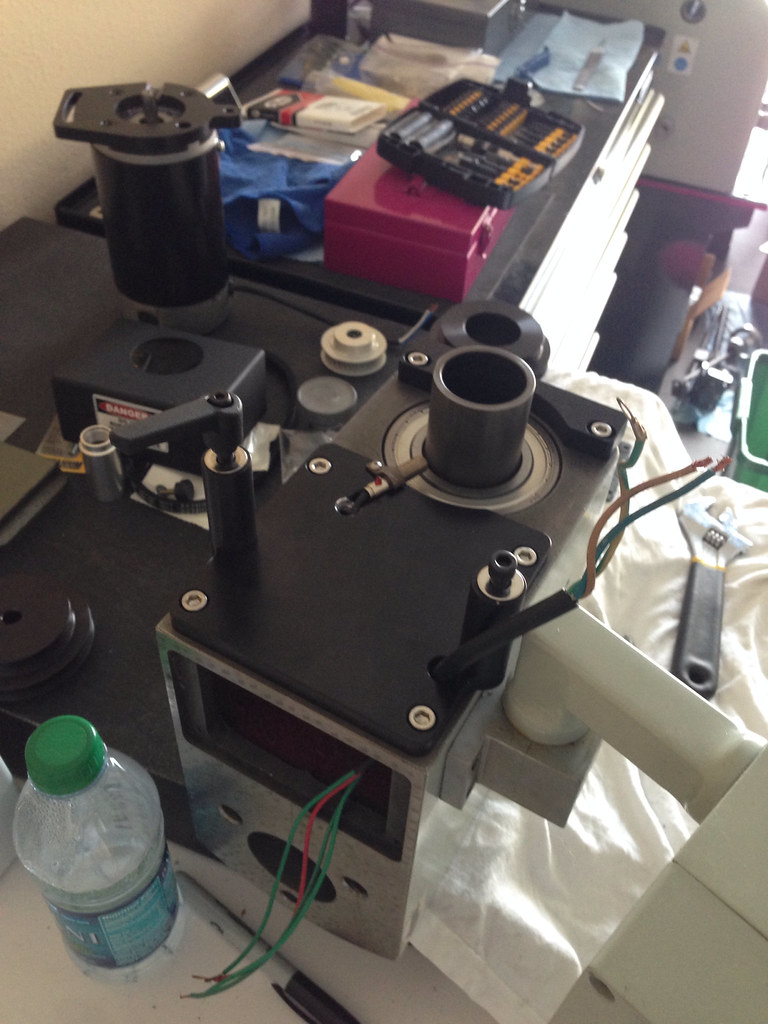
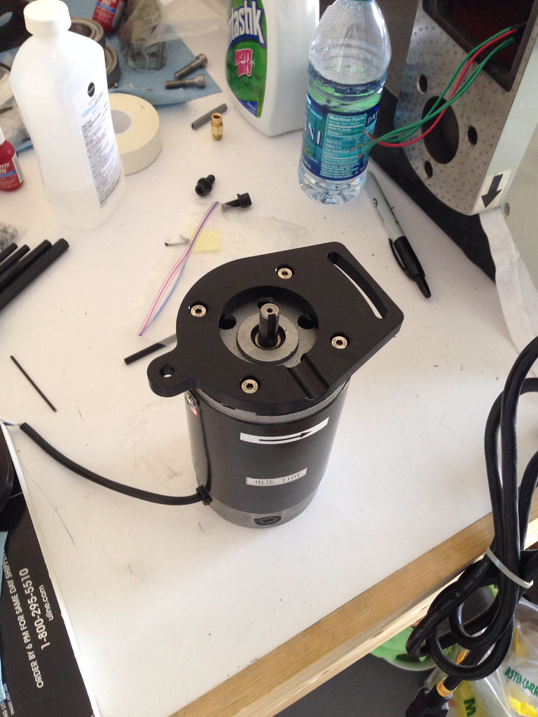
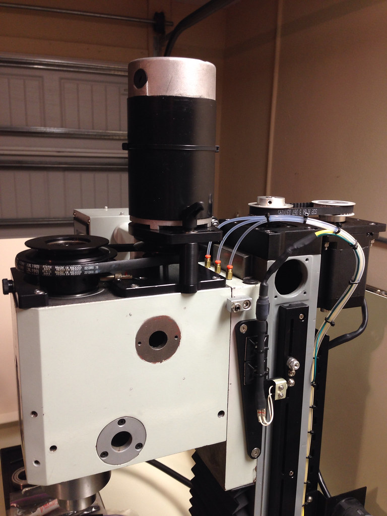
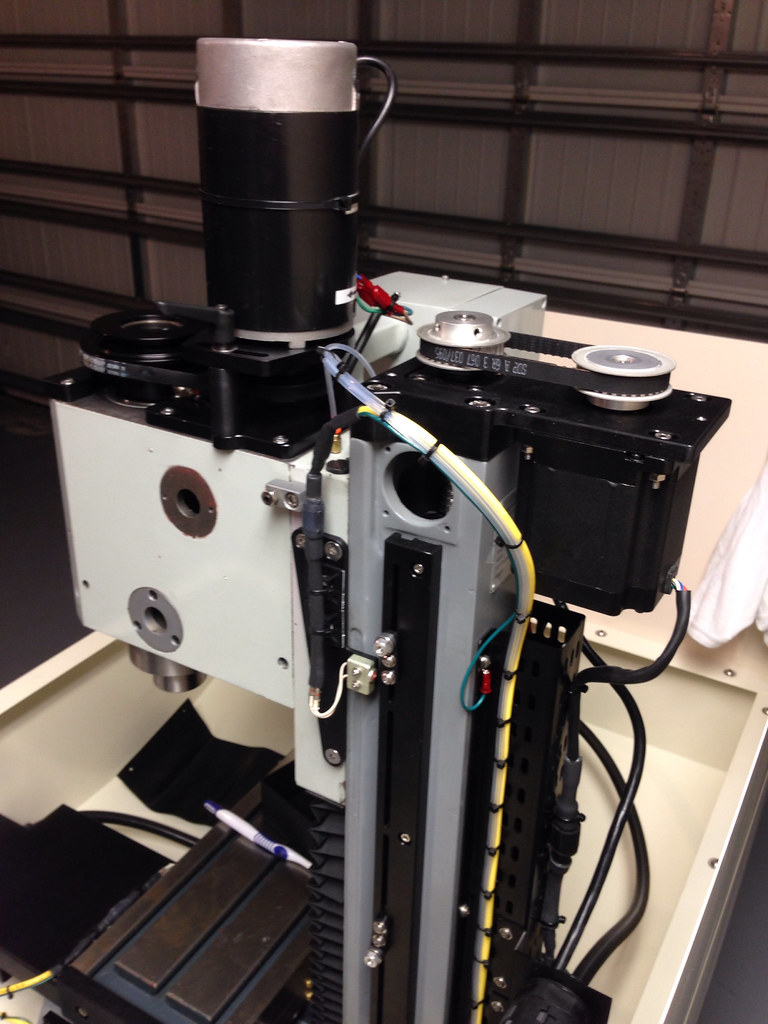
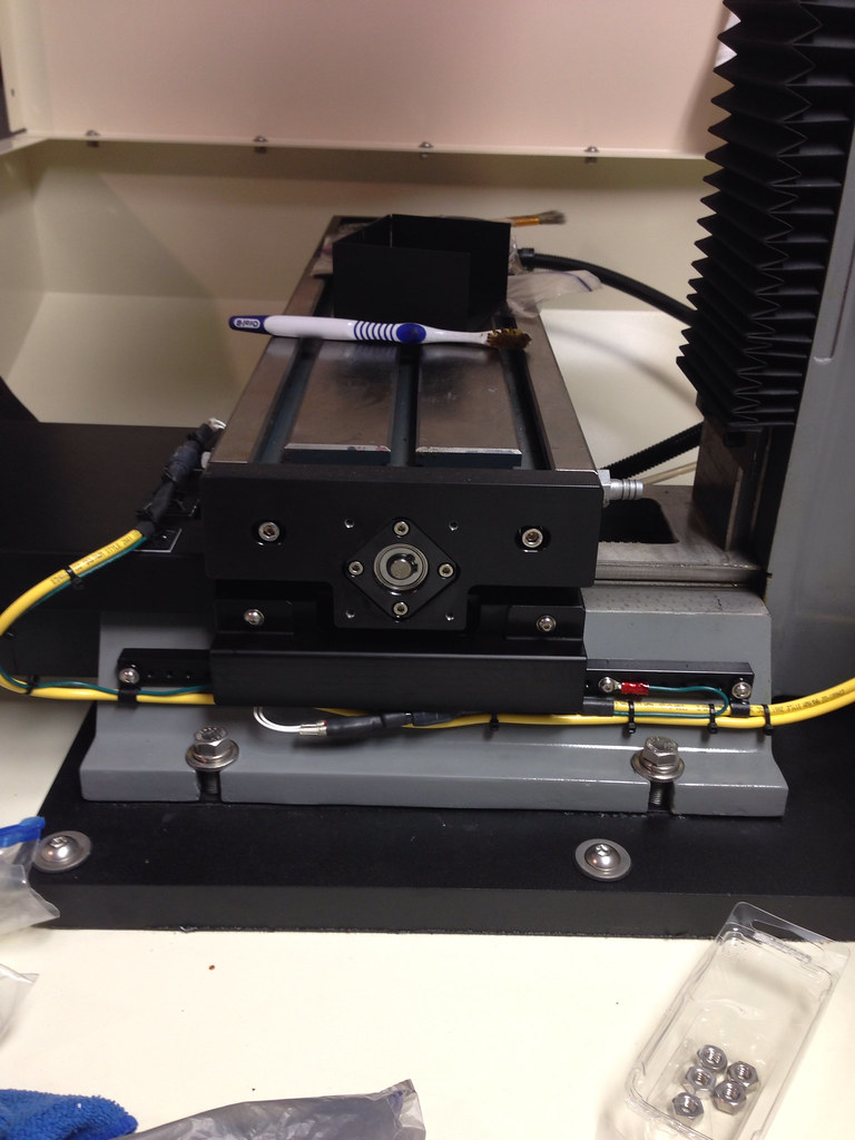
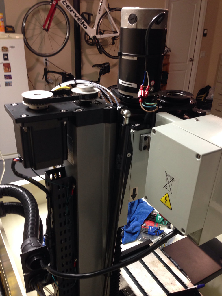
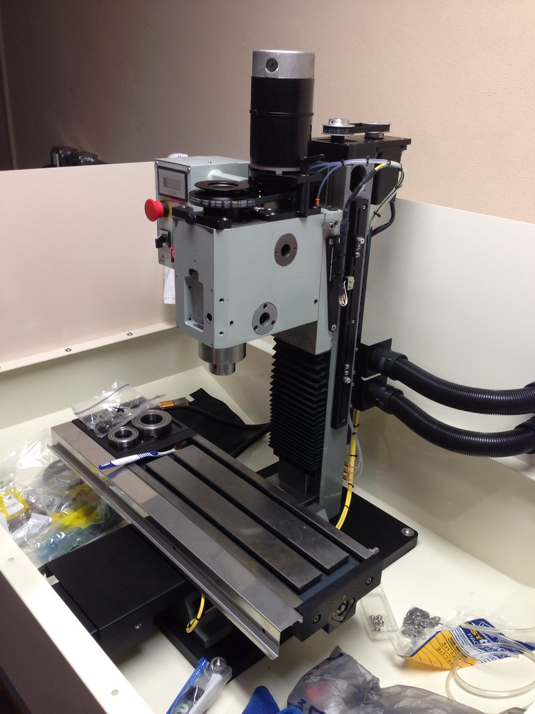
    I have been doing some work so I thought I would post up some pics. I should be done running the cables tomorrow and hopefully have it moving by the end of the weekend

    Putting together the front panel:


    Putting capacitors across the leads to the fans to reduce noise (100uF, 63VDC):
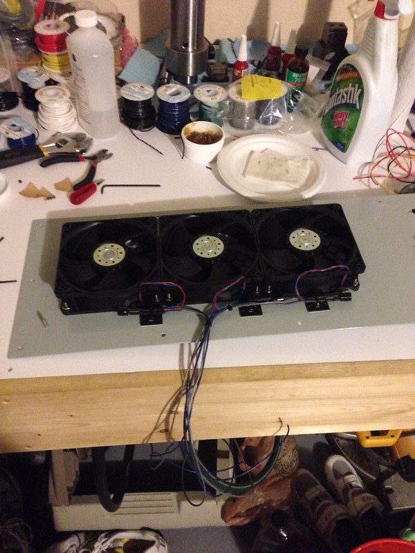


    Fans wired up:


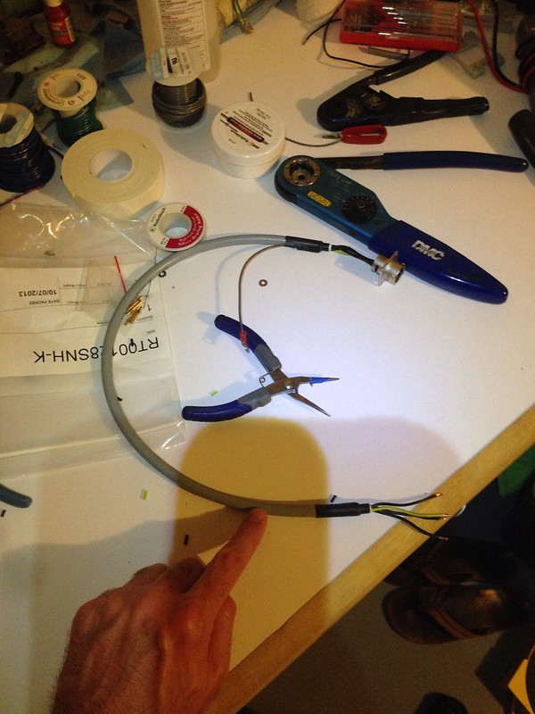
    Stepper cable for inside the enclosure (cables are shielded, so grounding one end at a min or the shielding will work against you):


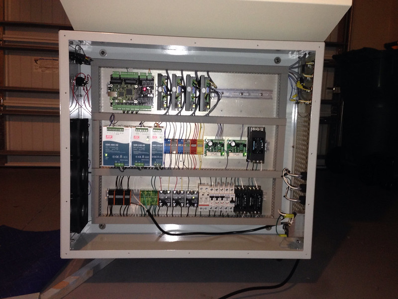
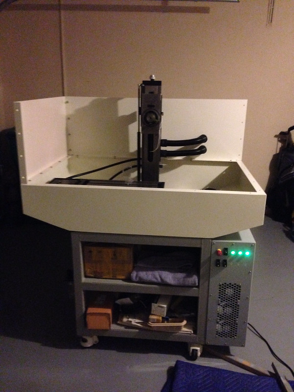
    Everything inside the enclosure all buttoned up (the wire duct made a big difference):


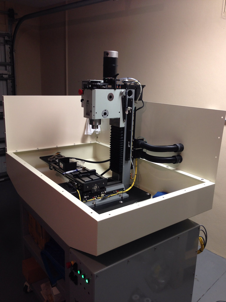
    Enclosure powered up and working:


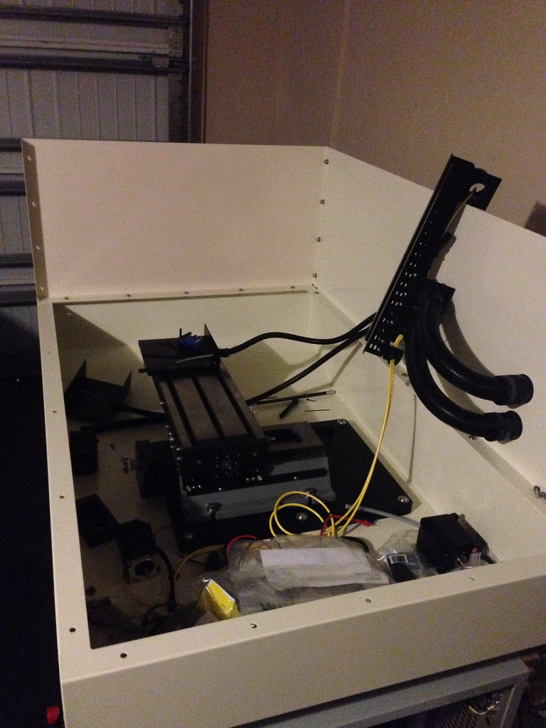
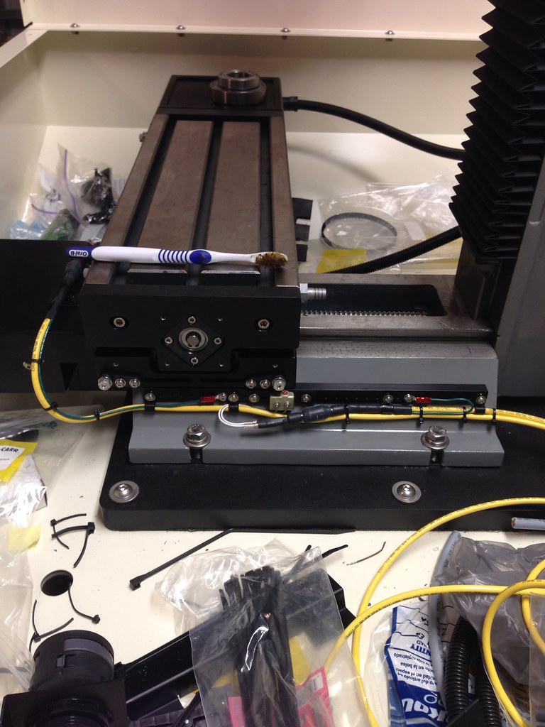
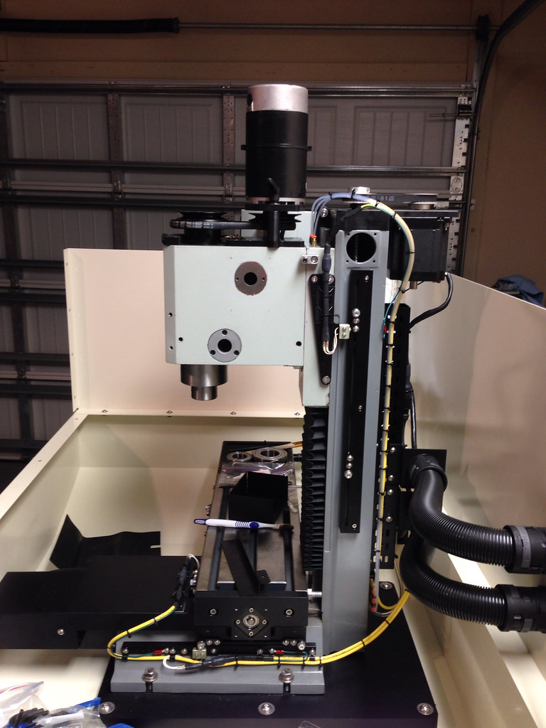
    Starting to run cables to the limit switches and steppers:


  3. #83
    Registered
    Join Date
    Jan 2012
    Location
    USA
    Posts
    139
    Downloads
    0
    Uploads
    0

    Default Re: Graham's Optimum BF20 Build

    I spy some anodized pulleys

    www.benchtopprecision.com
    | BF20/G0704 Belt Drive Kits | X2 Mini-Mill Belt Drive Kits |


  4. #84
    Registered
    Join Date
    Jul 2004
    Posts
    108
    Downloads
    0
    Uploads
    0

    Default Re: Graham's Optimum BF20 Build

    Luv the control cabinet, great job

    Will start mine soon.

    Cheers,
    Beano


  5. #85
    Registered
    Join Date
    Aug 2013
    Posts
    7
    Downloads
    0
    Uploads
    0

    Default Re: Graham's Optimum BF20 Build

    Hey Graham,

    First, let me say that I am really impressed with the work that you have done thus far. Your attention to detail is outstanding, and the build looks very professional.

    I am undertaking a similar project in Australia using the Titan TM25V (similar mill, with slightly different column arrangement). I am about to commence building the stand, and am weighing up the options. At this stage I am looking at using 2 inch square tube for a frame, and 1.5mm sheet for a chip tray. Are you able to confirm the thickness of the tube and sheet metal that you used? I am concerned with making sure that the stand has enough stability to handle the table being thrown around laterally. Your stand looks like it would be wide enough to cover this, but once your up and running it would be great to hear your thoughts.

    Cheers,

    Mick.


  6. #86
    Registered
    Join Date
    Nov 2012
    Location
    United States
    Posts
    220
    Downloads
    0
    Uploads
    0

    Default Re: Graham's Optimum BF20 Build

    Quote Originally Posted by BTP View Post
    I spy some anodized pulleys
    Yeah, I got the parts back and they look great. When I get the head mounted I will post some pics showing everything; it is a good kit

    MrBean_pm


    Luv the control cabinet, great job

    Will start mine soon.
    Thanks Beano
    Doing that control cabinet almost stopped me...not my favorite thing to do...


  7. #87
    Registered
    Join Date
    Nov 2012
    Location
    United States
    Posts
    220
    Downloads
    0
    Uploads
    0

    Default Re: Graham's Optimum BF20 Build

    Quote Originally Posted by Mick14 View Post
    Hey Graham,

    First, let me say that I am really impressed with the work that you have done thus far. Your attention to detail is outstanding, and the build looks very professional.

    I am undertaking a similar project in Australia using the Titan TM25V (similar mill, with slightly different column arrangement). I am about to commence building the stand, and am weighing up the options. At this stage I am looking at using 2 inch square tube for a frame, and 1.5mm sheet for a chip tray. Are you able to confirm the thickness of the tube and sheet metal that you used? I am concerned with making sure that the stand has enough stability to handle the table being thrown around laterally. Your stand looks like it would be wide enough to cover this, but once your up and running it would be great to hear your thoughts.

    Cheers,

    Mick.
    Thanks Mick, I have defiantly spent a lot of time and money on this...
    As for your questions, the chip tray is made from 16 gauge steel (.0598 inch thick), which is equivalent to 1.5 mm and is very sturdy. In hindsight, I think I should have made the top edge of the tray stop below the top of the mill table.

    The stand is made from 13 gauge (.095 inch thick) 2 inch X 2 inch box tubing. The stand 30 inches wide by 32 inches deep and is very stable, especially with the leveling casters. The stand by itself weighs 211 lbs. I have been driving my table around at approx. 200 ipm and the stand is not moving.

    Let me know if you have any more questions.

    Last edited by gcofieldd; 08-28-2014 at 11:48 PM.


  8. #88
    Registered
    Join Date
    Nov 2012
    Location
    United States
    Posts
    220
    Downloads
    0
    Uploads
    0

    Default Re: Graham's Optimum BF20 Build

    I thought I would post up a lesson learned:

    On my z-axis I have a 20mm ball screw and nut; when I first got it I took it apart, cleaned it, and completely filled all the ball tracks up with balls. It did not show up that way. After doing that I noticed the nut would catch periodically when turning it on the screw and now that I have the stepper hooked up to it, it seems problematic. I am going to take the z-axis back apart and remove one ball from each track and see if that fixes the problem, which I think it will. I believe the balls are packed too tight in the nut and are not transitioning smoothly into the return. After I take it apart I will let you know what I find out.


  9. #89
    Registered
    Join Date
    Nov 2012
    Location
    United States
    Posts
    220
    Downloads
    0
    Uploads
    0

    Default Almost done

    I took my mill back apart, repacked the ball nut removing one ball per track and it did not fix the problem, so I put the balls back in I had removed and then reassembled everything. I did some reading and saw someone mention “breaking in” you ball nuts/screws, so I am going to just ignore it and see if it goes away.

    After that I started building the head of my mill up, which entailed installing the belt drive kit I got from Scott at Benchtop Precision. I took some pictures of how I installed it, so maybe that will help someone else. One thing I have realized is that the quill adjustment knob off of the front of the mill head is very handy. I used it to install the bearing on the drive tube and install drive tube in the mill head.

    Once I got the head of the mill on, I connectorized the limit switches and finished running and dressing the limit switch cables. After that I started squaring the head of the mill to the column using Hoss’ method from his first tramming video.

    From the head to the column I have a 0.00175 inch downward nod. That is measured about six inches below the spindle nose. Is that worth trying to shim out? It seems like I would need a very thin shim.

    I also found I have about 0.125 inch I need to shim out of the column from the table, which seems like a lot...

    Anyway, I took a bunch of pics, so here they are.

    Mill pulled apart:


    Connectorizing limit switches:


    Installing the belt drive:


    Installing limit switch on the y-axis, dressing and grounding cables:


    Limit cables and oil lines installed and dressed in:


    Y-axis limit cover installed:


    Z-axis stepper motor grounded:


    Front stainless steel chip guard installed:


    Working on tramming:


    I guess now all I have to do is finish tramming the mill and learn how to use it:P

    I am a veteran, so I was able to get a student copy of Solidworks for $20, frickin awesome!
    I am going to combine that with HSMXpress and see how things go

    Hopefully next time I post it will be a video of the mill cutting.


  10. #90
    Registered
    Join Date
    Jan 2012
    Location
    USA
    Posts
    139
    Downloads
    0
    Uploads
    0

    Default Re: Graham's Optimum BF20 Build

    That's the cleanest that mill will ever be. Looks great though

    www.benchtopprecision.com
    | BF20/G0704 Belt Drive Kits | X2 Mini-Mill Belt Drive Kits |


  11. #91
    Registered angelfj1's Avatar
    Join Date
    Oct 2013
    Location
    Downingtown
    Posts
    4
    Downloads
    0
    Uploads
    0

    Default

    Graham et al: I just became aware of your project and I am impressed by the level of craftsmanship, etc. I am also CNC'ing a mill, a Grizzly G0704, so what you have documented here is important to me. However, I have hit a wall in trying to assemble all of your material. I can't open any of your attachments. Not the links, such as, http://farm9.staticflickr.com/8236/8...62affe7d_c.jpg, those are fine. But anything that looks like these do not work:

    Attachment 185252
    Attachment 185260
    Attachment 185254
    Attachment 185256
    Attachment 185262
    Attachment 185258

    When I click on one of these I get an error message, "Invalid Attachment specified. if you followed a valid link, please notify the administrator"

    So, does anyone know why I am not able to open any of the attachments. Is there another source for these documents?

    Thanks,

    Frank


  12. #92
    Registered
    Join Date
    Nov 2012
    Location
    United States
    Posts
    220
    Downloads
    0
    Uploads
    0

    Default Re: Graham's Optimum BF20 Build

    Quote Originally Posted by BTP View Post
    That's the cleanest that mill will ever be. Looks great though
    Thanks Scott! I hope you are right, I can't wait to get this thing dirty I have some shim stock coming in the mail. Once I get it squared and trammed the first part I am going to make is one of Hoss' spindle vibration dampeners. After that start making more parts for the mill.


  13. #93
    Registered
    Join Date
    Nov 2012
    Location
    United States
    Posts
    220
    Downloads
    0
    Uploads
    0

    Default Re: Graham's Optimum BF20 Build

    Quote Originally Posted by angelfj1 View Post
    Graham et al: I just became aware of your project and I am impressed by the level of craftsmanship, etc. I am also CNC'ing a mill, a Grizzly G0704, so what you have documented here is important to me. However, I have hit a wall in trying to assemble all of your material. I can't open any of your attachments. Not the links, such as, http://farm9.staticflickr.com/8236/8...62affe7d_c.jpg, those are fine. But anything that looks like these do not work:

    Attachment 185252
    Attachment 185260
    Attachment 185254
    Attachment 185256
    Attachment 185262
    Attachment 185258

    When I click on one of these I get an error message, "Invalid Attachment specified. if you followed a valid link, please notify the administrator"

    So, does anyone know why I am not able to open any of the attachments. Is there another source for these documents?

    Thanks,

    Frank
    Frank can you tell me the post numbers you are having trouble with? The post numbers are in the blue headers of each post on the right side.


  14. #94
    Member Fastest1's Avatar
    Join Date
    Nov 2009
    Location
    USA
    Posts
    4415
    Downloads
    0
    Uploads
    0

    Default Re: Graham's Optimum BF20 Build

    Fantastic work.

    A lazy man does it twice.


  15. #95
    Registered angelfj1's Avatar
    Join Date
    Oct 2013
    Location
    Downingtown
    Posts
    4
    Downloads
    0
    Uploads
    0

    Default Re: Graham's Optimum BF20 Build

    Hello Graham. yes, sure. The posts which contain "attachments" which I can not open and which result in an error message are:

    32, 33, 36, 37 and 43

    Best regards,

    Frank


  16. #96
    Registered angelfj1's Avatar
    Join Date
    Oct 2013
    Location
    Downingtown
    Posts
    4
    Downloads
    0
    Uploads
    0

    Default

    Well, I guess nobody knows how to fix this or perhaps no one gives a hoot!


  17. #97
    Registered
    Join Date
    Nov 2012
    Location
    United States
    Posts
    220
    Downloads
    0
    Uploads
    0

    Default Re: Graham's Optimum BF20 Build

    Quote Originally Posted by angelfj1 View Post
    Well, I guess nobody knows how to fix this or perhaps no one gives a hoot!
    Angelfj1, I tried to go back and reattach the pictures you asked about but it will not let me edit the posts--not sure why.

    Why don't you just PM me with any questions you have. I made drawings for the mods I did to the mill and for most of the parts.


  18. #98
    Registered
    Join Date
    Nov 2012
    Location
    United States
    Posts
    220
    Downloads
    0
    Uploads
    0

    Default Re: Graham's Optimum BF20 Build

    Quote Originally Posted by Fastest1 View Post
    Fantastic work.
    Thanks Fastest1


  19. #99
    Registered
    Join Date
    Nov 2012
    Location
    United States
    Posts
    220
    Downloads
    0
    Uploads
    0

    Default Re: Graham's Optimum BF20 Build

    Just to give you guys a heads up on what I have been doing, I installed the last oil line and the one shot lube system works. I need to install a metering or shut off valve on the oil line that runs to the bottom (x and y axis) so the z axis will get oil. I knew I would need to, just wanted to see how bad it was first and then make a decision. I found out my x-axis ball screw is bent to **** There is at least an 1/8 inch bend in it--not sure how I missed that. I may wait on fixing it. It seems like it works ok, just a little rough going in the +x direction.

    I modeled my first part in solid works (use ProE for work) and it was pretty straight forward if you are used to CAD. I had to do a little searching to find everything. I modeled the spindle vibration dampener Hoss designed. For some reason *.stl files do not work with SW and ProE, so I could not use Hoss’ model. Anyway, I installed HSMXPRESS, which is awesome, and created the tool paths for the part, but could not get it to post process. It tells me “Error: Failed to post intermediate NC data.” I am not sure what that means. Does anyone have any advice for using HSMXPRESS with Mach3?

    Here is the full output with error:

    Information: Configuration: Generic Mach3Mill
    Information: Vendor: Autodesk, Inc.
    Information: Posting intermediate data to 'C:\Users\Admin\Documents\SolidWorks\G-Code\1.tap'
    Information: Total number of warnings: 1
    Error: Failed to post intermediate NC data.
    Loading locale from 'C:\Program Files\HSMXpress\locales\english_us.xml'
    Code page changed to '1252 (ANSI - Latin I)'
    Start time: Friday, October 17, 2014 11:50:05 PM
    Code page changed to '20127 (US-ASCII)'
    Post processor engine: 3.9.5 36189
    Configuration path: C:\Program Files\HSMXpress\posts\mach3mill.cps
    Include paths: C:\Program Files\HSMXpress\posts
    Configuration modification date: Monday, February 10, 2014 3:01:42 PM
    Output path: C:\Users\Admin\Documents\SolidWorks\G-Code\1.tap
    Checksum of intermediate NC data: 831b07688cf4e3e7862688fc778f1ce9
    Checksum of configuration: 6166e5b8d039f1d89c8378ec3ba8dfb7
    Vendor url: Autodesk | 3D Design, Engineering & Entertainment Software
    Legal: Copyright (C) 2012-2013 by Autodesk, Inc.
    Generated by: HSMXpress 2014 R2.36580
    Warning: Work offset has not been specified. Using G54 as WCS.
    Error: Invalid coolant mode
    Error: Failed to invoke function 'onSection'.
    Error: Failed to invoke 'onSection' in the post configuration.
    Error: Failed to execute configuration.
    Stop time: Friday, October 17, 2014 11:50:05 PM
    Post processing failed.


  20. #100
    Member
    Join Date
    Aug 2014
    Posts
    103
    Downloads
    0
    Uploads
    0

    Default Re: Graham's Optimum BF20 Build

    Wow that an extremely neat job your doing there. Nice Build.


Page 5 of 10 FirstFirst ... 2345678 ... LastLast

Tags for this Thread

Posting Permissions

  • You may not post new threads
  • You may not post replies
  • You may not post attachments
  • You may not edit your posts
  •  


About CNCzone.com

    We are the largest and most active discussion forum for manufacturing industry. The site is 100% free to join and use, so join today!

Follow us on


Our Brands

Graham's Optimum BF20 Build

Graham's Optimum BF20 Build