Reply with Quote
First off, beautiful looking mill. Nice build here, one day when I upgrade too a larger machine, the GMT vise is what I want to get. They look beautiful


Thanks!Originally Posted by vigilante212

As noted above backlash is excellent but I have to get steps per inch dialed in perfect to give a concrete number.
I'll give you a total cost in the next couple days.
Serge
First off, beautiful looking mill. Nice build here, one day when I upgrade too a larger machine, the GMT vise is what I want to get. They look beautiful
Thank you very much Speeds.
The Glacern truly is a fantastic vise. Every bit as good as a Kurt, maybe better.
One thing I don't quite understand is why the steps per inch would need tuning - if you know the pitch of the screws and the ratios on any belt drive you might have on them, there's only one correct value, isn't there? Or are you talking about mapping the error along the entire length of the screw?
Nice work. Thanks for your write up of how you leveled the ends. I have been thinking of making a very small HSM mill with about 200mm travels based on two granite steps which I can buy from the hardware store for €20 each.
How did you get the vertical column aligned in "C"? http://www.cnc-toolkit.com/index.html
Regards,
Mark
Yes, logically you would think it would be a simple conversion. I found the calculated values to be out a bit in actual machining and adjusted accordingly. And before anyone, asks, yes the axis were all aligned with an indicator. I can't really explain it but it is moving how much it should be with the tweaked values.
I'm not doing any error mapping. They are Japanese ground screws, error is in the tenths over a foot. No biggie.
Cool idea. What do you have in mind for the spindle?
I looked at granite for a while (granite surface plate base) but reading up on drilling granite, making and installing inserts, etc... scared me off. Plus I was worried about the inserts creeping out after glue. Aluminum is easy to work with and familiar. This machine is rock solid, no vibration at all in the cut. I'd have to have a much beefier spindle and a lot more power before worrying about flex, vibration and resonance.
Forgive me if this sounds dense, but why would the C axis matter at all on a 3 axis vertical mill? The head just moves up and down.
Serge
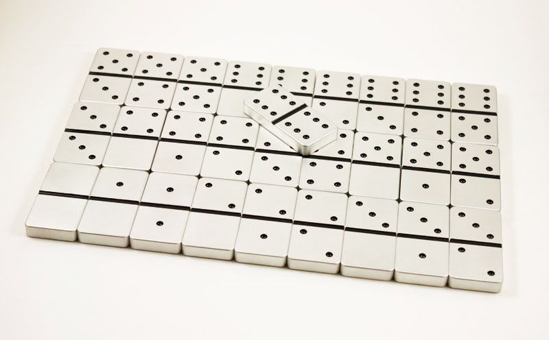
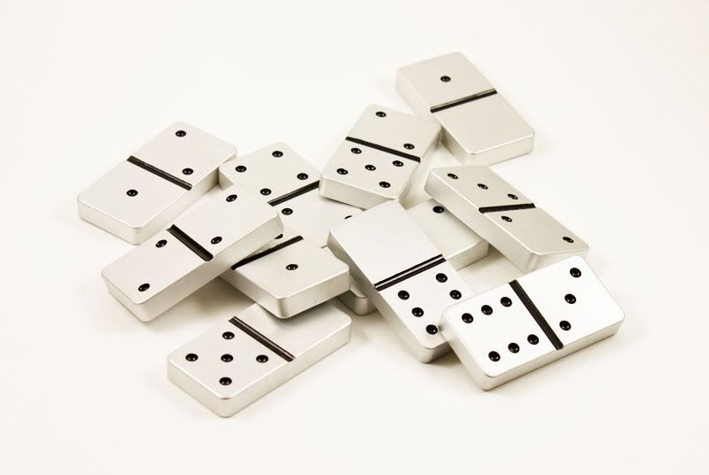
OK, the dominoes are all done. They are 1.75" by .875" by .25" thick. The finish is a bead blast with basic black paint-fill.
It's very interesting. It possible to mill steel or stainless?
I guess the spindle should have the power up.
Mongkol
I don't mean to be a PITA, but if you can't explain it, you probably haven't found the problem yet! I had a similar sounding issue with my mill - I blamed everything from the screws to the encoders, and in the end it turned out to be a loose ballscrew mount. It seemed solid until slipped repeatably and my parts were fine in the X-dimension but a little out in the Y.
Please have a look at : http://www.cnczone.com/forums/showpo...&postcount=374 and http://www.cnczone.com/forums/showpo...&postcount=398 and see if it sounds familiar.
Those dominoes look great by the way!
Serge, what I meant with the question was, how did you get the column aligned in rotation to the base when you mounted it?
Regards,
Mark
Sure, steel and even stainless milling would be possible. The depths of cut and feed rates would have to be pretty conservative though. I don't think it would have much problem with leaded steel or 1020 though.
Serge
I'll double check all mechanical connections (ball-screw mounts, bearing pre-load, couplers, etc...). But everything was lock-tited and torqued and there is no play on all three axis just trying to move them by hand. The step values have also gone back and forth a bit when I was trying to home perfectly in, I'll check with the calculated values. But really, if the dimensions are what they are supposed to be and the surface finish is good that is the goal. If the mechanical stuff is fine, finished product is fine but steps per inch values a bit off from calculated value I couldn't care less.
Some more milling will be done shortly so I can see where things are at.
Thanks for the compliment on the dominoes.
Serge
In terms of alignment, the Z rails were aligned two ways. The first was to make sure they were going straight up relative to the base block from side to side. This was done when the rails were mounted by indicating. The second was to make sure the rails were going straight up from front to back. I had to shim a bit under the column on one end to get this where it needed to be (under .001" over 3"). With this alignment, the head travels straight up and down relative to the base and table of the mill.
In terms of rotational alignment of the column relative to the base nothing was done because it doesn't really matter with a 3 axis vertical mill. The head just moves up and down.
Serge
Milling video is up:
"http://www.youtube.com/watch?v=9vWqH3gp62g"]YouTube- Blade Stage 1.mp4
Watch on Youtube for the 720p version.
Very nice - what is that part?
It sounds to me like you have a good solid machine there, but perhaps you could do with a bit more spindle power - you can just hear the revs drop a bit during the heavier cuts. But the removal rate is pretty impressive IMHO.

wow very neat!
im a 4 year lettermen on my high school golf team and love golf... ive been talking of making a putter for quite a while but couldn't think of a good way to connect the shaft to the putter.
I never thought i would see another person trying to make a putter at cnczone so i am fascinated. Do you mind if i shoot you a pm sometime?
Also, most putters have a 2 degree loft... is yours a right angle?
Great work.
cheers!
Digits: I'm running a 3/8", 3fl high helix Sowa carbide at 5,000RPM, 30 IPM, .05" DOC.
The part is a putter.
The motor/speed control is one of these:
http://www.pennstateind.com/store/TCLVSKIT.html
It has load compensation. It seems to take a bit (half a second?) for it to kick in. So at the start of a heavier cut you can hear it drop a bit then it kicks back in.
The mill is working great, so I'll keep the motor for now.
Teyber12: Feel free to shoot me a PM.
This is only stage 1. I haven't milled the face or anything yet. Stage 2 will mill the sole, then I'll drill the shaft hole, then stage 3 will mill the face. It will have 2* loft. Most putters have 4*.
Serge
I spent several years designing and machining putters for a living. Over that time I machined thousands of putters. I never thought making thousands of putters on a cnc machine(atleast not the models we did)was a profitadble way to do things. I did often think that you could have a decent business making putters as a custom to the golfer type product. I stared prototyping with brass and bronze but we cut production rus in steel and had them plated in gold or rhodium with gold plated weight.
Will you be pouring a polyurethane face or leaving them solid?
Good luck with the operation. I think you have the right idea!
Judleroy
Thanks judleroy. Yep, they are custom to spec and look.
Vid of stage 2 is up: "http://www.youtube.com/watch?v=QSpbzYRqN7g"]YouTube- Blade Stage 2.mp4
Serge