DIY aluminum vertical mill build


Page 1 of 5 1234 ... LastLast
Results 1 to 20 of 82

Thread: DIY aluminum vertical mill build

  1. #1
    Registered
    Join Date
    Mar 2008
    Location
    Canada
    Posts
    201
    Downloads
    0
    Uploads
    0

    Default DIY aluminum vertical mill build

    Hey guys,

    Before getting started I want to thank the owners of this forum for offering such a wealth of collective information for free. I also want to thank Leeway and Arie for their great and very detailed build threads that inspired me and helped to provide ideas.

    A little background: I have a small business designing and making putters from brass and aluminum. My existing mills were both Sherlines: one CNC and one manual. Although quality mills they certainly lack in rigidity, speed and power. I was very limited in the machining approaches I could use and to a certain extent the designs possible. Plus, total cycle times were obviously a bit long.

    I wanted a new CNC mill. The garage is detached, not heated or insulated and has one breaker. The basement is finished and is full of stuff. This had to be put where the existing mills were, in a bedroom. Options were very limited for a machine that would be "practical" in a bedroom, pretty much 300 pounds or less. To me, the X2 and X3 based machines had no appeal for both quality and other reasons. The Minitech that I liked was the 3 pro (With linear ways and ballscrews), but this thing was $14,000+ and looked a little light duty. It would remove material faster than the Sherline but not to the degree that would justify that amount of money. That left Wabeco, the most likely candidate. At the time it was $10,500 (Now about 9K). I would also want an ISO30 taper ($600 option) as MT2 tooling doesn't really appeal to me. The ISO30 tooling along with having a mill shipped to Canada from California would cost me a fortune.

    That left me with building a mill. After viewing threads on here (Lee Way, Arie, etc...) I decided on a general size and configuration. Vertical, about 11" of X, 6-7" of Y and 10" of Z, fully supported table (long saddle, short table).

    The main frame components were a real problem. I didn't have much to work with, manual and CNC Sherlines. The day job is in a machine shop but time there is for them and not my projects, especially not something home business related. A bench top drill press (10" Canadian Tire one) was picked up to help me out. The only viable option seemed to be aluminum extrusion (8020 or the like) heavily cross braced and reinforced. Leeway had built quite a mill with the stuff, but he used huge linear rails for the size of the machine (25's and 35's) to strengthen it up. I started to design a mill around 8020 and then came across two 6" by 5" by 24" blocks of solid aluminum at a local scrap place. I went back, purchased one, checked it over and then bought the second. They were 70 pounds each, total cost $300.

    Ground ballscrews and linear rails were purchased on ebay. The rails: 20mm for X and Y and 15mm heavy pre-load for Z, all THK. The ballscrews: NSK 20mm, 5mm pitch for Y, NSK 14mm, 5mm pitch for X, Kuroda 15mm, 4mm pitch for Z. A mill was designed around this an X2 spindle and the aluminum blocks.


    Similar Threads:


  2. #2
    Registered
    Join Date
    Mar 2008
    Location
    Canada
    Posts
    201
    Downloads
    0
    Uploads
    0

    Default

    After receiving and checking over the X2 head from LMS, it didn't exactly blow my skirt up. Eight tenths of run out in the taper. Add in a Tormach collet, holder and the total runout could be terrible depending on how it stacked. Even though I had bought the belt drive conversion kit as well I decided to cut my losses instead of buying a bearing puller kit and new bearings.

    Finley spindles were looked at. The price was too high ($1200) and it was a cartridge and would need an accurately bored mounting block. Plus it was ER20 so any kind of repeatable tool changes were out of the question.

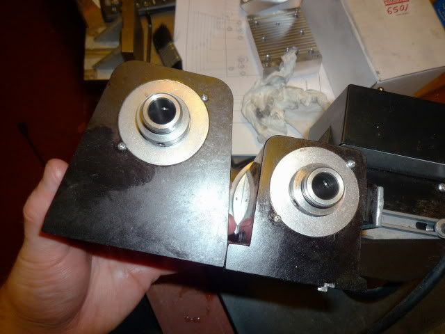
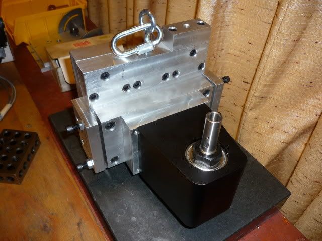
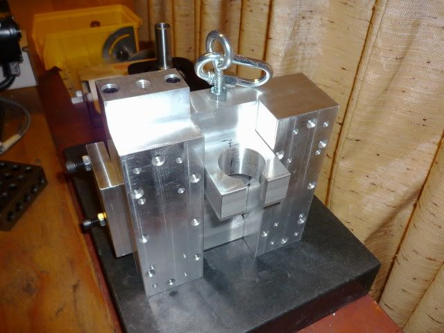
    So, I checked out the Sherline industrial spindles. They had one with what appeared to be a much beefier case than the stock one. I new the shaft and bearing set were the same. But to me, the weakness in the Sherline spindles on the factory machines was in the mounting and the thin case. If a beefier one could be mounted solidly, I figured it would work quite well.

    http://www.sherlineipd.com/spindles.htm
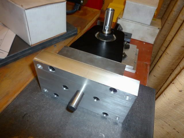
    P/N 6502-3/4-16/#1 Morse spindle with 2-step "V" belt pulley

    Here is a pic comparing a spindle off a Sherline mill/lathe to the industrial one. Quite a difference.


  3. #3
    Registered
    Join Date
    Mar 2008
    Location
    Canada
    Posts
    201
    Downloads
    0
    Uploads
    0

    Default

    First step in terms of actual construction was the two main blocks, base and column, getting these flat and perpendicular on the important sides.

    Here are the main blocks as I found them:


    On the base block, the top surface needed to be flat and one of the ends perpendicular to this as well as flat. On the column block the top surface needed to be flat and both ends perpendicular to this as well as flat. On one block, one of the large surfaces was pretty flat. On the other, not so much. The ends on both blocks were not machined.

    The first step was making one large surface on both blocks flat. With no mill, I decided to sand them. The whole large surface was scribbled with a sharpie. Some 80 grit sandpaper was double-sided taped to an 18" by 12" granite surface plate. The block was placed on a dolly and braced against the dresser and the granite plate was pushed back and forth over the block. The sandpaper was cleaned and the marker on the block checked every 50 strokes or so. Needless to say, it took a long time to get that surface flat (and a couple sandpaper changes), but eventually it was flat to .001" over the whole rail bearing surface.


  4. #4
    Registered
    Join Date
    Mar 2008
    Location
    Canada
    Posts
    201
    Downloads
    0
    Uploads
    0

    Default

    The next step provided a real challenge, how the heck am a going to get the end surfaces perpendicular to the large flat surfaces? Not only that, but one of the side surfaces would have to be perpendicular to the large top surfaces to be able to accurately mark lines using the height gauge to locate holes.

    One of the blocks had a side surface that was really close to perpendicular in regards to the top flat surface. The other did not.

    Eventually a plan was hatched: using shims and JB weld (metal putty) would get the job done. The block was placed on the surface plate with the side surface down and the flat top surface towards me. This was checked with a square to see how much shim would be needed. I added shim from a cheap feeler gauge set under the side surface in the right spot until it was perpendicular with the top surface. The shim was then super-glued in place. Now for the fun part. Saran rap was stretched tight over the surface plate and secured with masking tape on the side surfaces, adjusting the tape to make sure it was pulled tight. Then non-petroleum based (important, oily stuff will crinkle it up) silicone spray was used liberally on the whole saran wrap surface. The JB weld was mixed up and applied to the side surface, more being put around the shim. Then the block was placed down on the plate, with the weight of the block pushing the JB weld down to the shim. It was left on the plate for a good 6-8 hours and then pulled off and any JB protruding off the sides trimmed off with an Xacto knife. Then it was allowed to fully cure for another 24 hours or so. It was then sanded down a bit with sandpaper double sided taped to the granite block until the shil was virtually exposed. Presto, perpendicular.


    I used the same technique with the ends, checking with shim and gluing the right amount in the right places.


    A mistake I made was using feeler gauges on the end instead of brass shim stock as I needed to drill through a place that was occupied with shim. It had to be "peeled off" and JB re-applied to the area, placed on the saran wrap surface plate dealie and then sanded down. The rest of the procedure was the same, though I had to do a little more fiddling with a file to get the end to where I wanted them (perpendicular to .0015" over 5")


    There we go, main blocks ready.


  5. #5
    Registered
    Join Date
    Mar 2008
    Location
    Canada
    Posts
    201
    Downloads
    0
    Uploads
    0

    Default

    I wanted to work on the column (Z axis) next. First up, the holes for the rails. This was done with surface plate scribing to get two hole locations for the first rail (As far apart as possible with the 10" height gauge). These were optically center punched, drilled on the drill press and tapped.
    http://www.leevalley.com/wood/page.a...=1,42936,50298

    With the rail positioned parallel and straight to the block with adjustable parallels the two rail screws were tightened. Then the remaining holes were transfer punched, drilled and tapped.

    For the second rail the first two holes were done as before. Then the first rail was re-installed parallel to the block. Using regular and adjustable parallels the second rail was placed parallel to the first and the two screws were tightened. Then transfer punching, drilling and tapping as before. The holes for all three axis were done this way.


  6. #6
    Registered
    Join Date
    Mar 2008
    Location
    Canada
    Posts
    201
    Downloads
    0
    Uploads
    0

    Default

    Next up, head assembly. First up was modifying the Sherline spindle for more solid mounting. Out of the box, the spindle had two 1/4-20 tapped holes and a key-way. This was not enough. I drilled and tapped four more 1/4-20 holes, one at each corner.


    The plate that the spindle attached to had a .050" deep cutout that was less than half a thou wider than the spindle itself, providing a snug fit. So, the spindle would be held in place by the cutout and secured with triple the original amount of hardware. The spindle plate attached to another plate with a milled cutout barely wider than the plate and was secured with six 1/4-20 screws. A 1/2" dowel was pressed into this second plate.


    The rest of the head is shown assembled below. The spindle plate assembly is located and rotates about the dowel on the main plate and is secured with four 5/16-18 screws. Two tram plates on the side help to tram the head and provide additional support. The eye bolt and coupler are there for the counter weight.


    I did a mock up after with the motor. The motor is from a Penn State industries DC variable speed motor kit originally for the lathes they sell. It is a 1/2HP, 1700 max RPM motor. The control is a turned knob, 20-100% of motor RPM with load compensation. It's on sale right now for $100.

    http://www.pennstateind.com/store/TCLVSKIT.html


  7. #7
    Registered MRM RCModels's Avatar
    Join Date
    Jul 2007
    Location
    USA
    Posts
    675
    Downloads
    0
    Uploads
    0

    Default

    Design looks good. Are you looking to get more travel than your present cnc mill with the same performance? I'd also advise making some denim bellows for the linear slides. Really helped mine with the swarf. Did you ever look at a 1.5kw Chinese spindle with VFD option. For what you're doing might be worth the investment.

    You sanded both surfaces perpendicular by hand ? You have a bigger pair than I do.


  8. #8
    Registered
    Join Date
    Mar 2008
    Location
    Canada
    Posts
    201
    Downloads
    0
    Uploads
    0

    Default

    The remaining parts construction is pretty similar, plates with holes. Smaller parts like the ballnut blocks, stepper plates and smaller riser plates were done completely on the Sherline. Larger components were done through sanding, some Sherline facing where possible (Like on the Y end plate) and drill press.


    Last edited by sergizmo; 01-02-2010 at 03:56 AM.


  9. #9
    Registered
    Join Date
    Mar 2008
    Location
    Canada
    Posts
    201
    Downloads
    0
    Uploads
    0

    Default

    The components were done, it was time for mock up.

    The base was started first. The rails were aligned as noted before. In this pic you can see the legs with vibration dampening mounts along with the plastic "soft stops" at the ends of travel.


    After the rails were on the Y risers were next to go on. There were risers for all three axis, they provided clearance for the ballscrews. They were aligned with parallels.


    The Y end plate, saddle and ballscrew were next to go on. The saddle was tricky, Some JB weld had to be added and sanded in the middle to get it flat on the rail mounting side. There was simply too much material to remove if sanding alone was used. The other side was made parallel to this through indicating and shimming underneath in the middle section (where the risers would contact) until the top was reading flat. Then the shims were glued on and the JB weld trick was used as before. Success.


    The X rails went on next.


    Here we see the finished X-Y assembly. X end plate, ballscrew, X risers, table and stepper spacers have been added.


    The Z rails were screwed on. Then the Z bottom and top plates went on as well. the column was then lifted into position and screwed down with 10 5/16-18 cap screws.


    The rest of the head was mocked up.


    From the side...


    Couplers were bored out on the lathe to fit (Oldham style from sdp-si) and the stepper motors were installed. I then did a bit of testing, just jogging everything around, it went well.


  10. #10
    Registered
    Join Date
    Mar 2008
    Location
    Canada
    Posts
    201
    Downloads
    0
    Uploads
    0

    Default

    With mock up completed, the mill had to be torn down (with all the hardware going into Plano style organizers). It was then re-assembled, for real on the center of the bench. This time, blue Loctite was used and everything was indicated to align it. Assembly took much longer when done properly.

    A counter weight system was added as well. The head with motor weighed in at about 22.5 pounds. A counter weight of 15 pounds was made up in a PVC tube connected by a cable running on two pulleys. This was to lessen the load on the Z stepper, prevent the head from dropping when the steppers were not under power and increase smoothness and performance of the Z axis in general. I prefer a counter weight to springs or gas shocks because it is out of the way, doesn't limit travel, and is always the same in terms of force unlike a spring or shock near the end of travel. It will also never bind or leak like a shock can.


    Way covers were made from "heavy duty" clear shower curtain liner, the same stuff used in shops to keep chips in an area. It's pretty tough stuff, and should last a long time. It is also really thin and flexible so shouldn't bind or get caught up. The covers were made in two pieces; a "skirt" that went all the way around the table and covered all of the X and Y axis, and a strip that came down from the bottom of the column. Attachment was via thin aluminum strips that can bee seen in the pic.


  11. #11
    Registered
    Join Date
    Mar 2008
    Location
    Canada
    Posts
    201
    Downloads
    0
    Uploads
    0

    Default

    Electronics are by CandCNC. Initial performance looks to be very good. Fast and plenty of power. I got the Blade runner complete system with upgraded steppers and power supply (600oz-in and 48V). Yes, 600-oz in NEMA 23's running off a Gecko 251 based system.

    There is one problem though. I had problems with the X axis not moving below certain speeds (initially 8 IPM) once the system had heated up after a while. Mach would say it was moving but the motor didn't turn. I sent the unit back and it was fixed. The problem remained, but wasn't as serious (threshold was now 4IPM). Also, it wouldn't move in .001" increments on the X at any speed, although Mach was saying it was.

    The enemy seemed to be heat. It worked great initially, but the x axis problems started popping up once it had heated up a bit. The controller case is extremely cramped with limited ventilation and one fan. There is a transformer on the internal power supply that is right beside the X axis driver, my guess is the heat from that was causing problems. Anyways, I took the top cover off and drilled dozens and dozens of holes on the top and sides. I then went looking for a fan and as it is winter in Canada they are a bit out of season. I settled on a space heater with a "fan only" mode. It isn't as powerful as I would like, but seems to work well enough.

    The controller has a temp sensor on the bottom plate. Before mods it was topping out at 100F. Now it tops out at 88F. That is the temp at the center, temp on the X driver would I assume be greater.

    After these modifications the electronics work great! I think in terms of performance this fantastic for a NEMA 23 system, and further use should confirm that. The Blade runner comes with a load meter as well, to show the percentage of available power the system is drawing. There is a custom Mach screen included that shows this. To me, this is a great feature! Feedback on how hard the system is being pushed.

    Pic shows the electronics and compressor. From L-R: Upgraded power supply with instructions on top, PC, Blade Runner control with fan on top, compressor (Canadian tire 8 AMP dealie, works great!).


  12. #12
    Registered
    Join Date
    Mar 2008
    Location
    Canada
    Posts
    201
    Downloads
    0
    Uploads
    0

    Default

    The first vise that was purchased was a screw-less design, 3" wide jaws, made by STM. Clamping wasn't consistent and it quickly broke on me with the tiny retaining screw for the rod giving out. Junk. So I bought a 4" Glacern for the sale price of $230.00 plus shipping ($79 to Canada). What a great deal and fantastic vise. Bed height within .0002", sole parallel to bed within .0002", jaws perpendicular to bed within .0003". There is no slop at all, it is very solid. I still have to get some 3/8" hardware and mount it.

    You can't really see the numbers on the sheet due to flash, but here it is anyway.


  13. #13
    Registered
    Join Date
    Mar 2008
    Location
    Canada
    Posts
    201
    Downloads
    0
    Uploads
    0

    Default

    Miscellaneous stuff:

    The spindle has a 15 tooth pulley and the motor has a 45 tooth pulley with an L timing belt, all from sdp-si. Both were bored on the lathe to fit. As the motor RPM is from 340-1700 RPM at the spindle is 1000-5000. I wish the bottom end was a bit lower in case I do some steel but I want that high end. I can always get a 25 tooth pulley for the motor later on and switch it out for the situation without much fuss.

    Performance. I didn't get much time with the mill until that POS vise gave out on me. Material removal rate with the Sherline CNC was .025" DOC at 10IPM in 6061. With the new mill it was at .050" DOC at 20IPM in 6061 and the finish was mirror smooth both on facing and profiling. I'm sure the feed could be pushed up faster, I'm going to try 25IPM right away when the Glacern is mounted.

    Tooling. I'm using the Sherline end mill holders. Run out is excellent with these: anywhere from .0003" to .0006" at the tool when screwed on to the spindle. The X2 head had .0008" in the spindle bore alone, after tolerance stacking I bet it would be pushing a thou and a half at the tool. Plus these tool holders are nice and cheap at $30US per. I also have a single insert face mill, 3 drill chucks and a boring head, all Sherline.

    Weight: The two main blocks are 70 pounds each, totaling 140. Head assembly with motor is about 23 pounds. The rest of the aluminum (head parts not included) is 43.5 pounds. Steppers are about 2.5 pounds each for another 7.5 pounds. Linear rails, and ballscrews I would guesstimate at another 12 pounds total. Counter weight is 15 pounds. So total machine weight = 240 pounds.

    Well, that's it for a bit guys. Thanks for reading.

    Serge

    Last edited by sergizmo; 01-02-2010 at 05:49 AM. Reason: added stuff


  14. #14
    Registered
    Join Date
    Mar 2008
    Location
    Canada
    Posts
    201
    Downloads
    0
    Uploads
    0

    Default

    Quote Originally Posted by MRM RCModels View Post
    Design looks good. Are you looking to get more travel than your present cnc mill with the same performance? I'd also advise making some denim bellows for the linear slides. Really helped mine with the swarf. Did you ever look at a 1.5kw Chinese spindle with VFD option. For what you're doing might be worth the investment.

    You sanded both surfaces perpendicular by hand ? You have a bigger pair than I do.
    Thanks.

    The performance is much better. It is waaaaaaay more rigid than the Sherline, the frame being 6" by 5" solid aluminum for both base and column. No backlash (.0001" on all axis, measured with a .0001" test indicator) and much, much faster. Jogging at 120IPM no sweat. I turned it down to 100IPM because much faster than that was kind of scary.

    The perpendicularity was mainly achieved by gluing shims to the end of the block of the right thickness in the right places and testing this with the block stood up on the surface plate with a square. Then the JB weld was used. After that I did some checking and a little draw filing to get it square within .0015" over 5". Most of the sanding was done to get stuff flat.

    I don't like the look of those Chinese spindles for several reasons. First, they are a bazillion RPM, min RPM is too fast. Second, it is a cartridge type spindle and would require a precisely bored hole in a mounting block, something I can't do at home. Third, ER nose. I can't preset my tools in a multiple tool program. And fourth, it's Chinese made. The Sherline spindle is of much better quality.


  15. #15
    Registered
    Join Date
    Mar 2008
    Location
    Canada
    Posts
    201
    Downloads
    0
    Uploads
    0

    Default

    Any questions, comments, suggestions, ideas, criticisms, etc... ?


  16. #16
    Gold Member BobWarfield's Avatar
    Join Date
    May 2005
    Location
    USA
    Posts
    2502
    Downloads
    0
    Uploads
    0

    Default

    Quote Originally Posted by sergizmo View Post
    Any questions, comments, suggestions, ideas, criticisms, etc... ?
    Nice project.

    One thought:

    If you had it to do over again, make the base wider. If you look at commercial CNC's versus those intended for the home, I always notice the saddle is very wide on the commercial units. You want the support of the table linear rails tied to the base as far apart as possible I think. This would be particularly easy to do on your machine.

    If you want even more rigidity, you could fill the base and column with epoxy granite. It made at least a 15-20% difference on my IH mill to do that.

    Cheers,

    BW

    Try G-Wizard Machinist's Calculator for free:
    http://www.cnccookbook.com/CCGWizard.html


  17. #17
    Registered
    Join Date
    Mar 2008
    Location
    Canada
    Posts
    201
    Downloads
    0
    Uploads
    0

    Default

    Thanks Bob.

    The base and column are solid (no cavity) 6" by 5" aluminum blocks. So there is nothing to fill. They clock in at 70 pounds each (6" x 5" x 24" x .098"lb/in^3). The spindle will fail before these monsters bend.

    It would have been nice to make the base wider, reducing saddle overhang. From what I had available at the time, these two pieces were the best option. Unfourtunately I didn't know about the local Metal Supermarkets at the time, they have some pieces that could have been used for the base. One was 8" wide by 3 1/2" thick, that would have done nicely.

    Serge


  18. #18
    Registered
    Join Date
    Mar 2008
    Location
    Canada
    Posts
    201
    Downloads
    0
    Uploads
    0

    Default

    ^^^^^^^

    To add to the above. The rail blocks on the base protrude about .2" off of each side. So there is 6.4" in the center of the saddle that is fully supported.


  19. #19
    Registered
    Join Date
    Jul 2007
    Location
    Sweden
    Posts
    887
    Downloads
    0
    Uploads
    0

    Default

    Hi,
    Very impressive build indeed! It shows what can be done with limted tools, dedication, some careful thought and "a bit" of elbow grease. Can't say I completely understood the "shimming/bondo process" of getting the important surfaces flat and perpendicular but that says more about me than you and/or the process ;-)

    Would love to see a video of it action once you get the Glacern vise mounted!

    Again, excellent work, thanks for showing us!

    /Henrik.


  20. #20
    Registered
    Join Date
    Mar 2008
    Location
    Canada
    Posts
    201
    Downloads
    0
    Uploads
    0

    Default

    Hi Henrik,

    Thank you very much!

    I'll try to explain getting the ends perpendicular a bit better.

    1) I stand the block up on the granite surface plate, with the down side being the end I want to square up.

    2) I "test fit" shims of various thicknesses under the end that is down and check perpendicularity with a square off the granite plate. I keep moving the shims around, and using different thicknesses and checking with the square both off the main flat surface and my reference side surface. After the end is square I note the positions of the shims with a marker.

    3) The shims are super-glued in the spots noted down with a marker.

    4) The granite plate is covered by saran wrap, stretched tight and the ends taped down to the sides of the plate with masking tape. I keep stretching the saran wrap over the plate by pulling and re-applying the tape until the top is a smooth surface.

    5) The saran wrapped surface plate is sprayed down liberally with non-petroleum based silicone spray.

    6) JB Weld is mixed up and applied to the end being squared up (The one with the shims).

    7) The granite plate is then placed on top of this end. The weight of the plate squeezes the JB weld down to the shims. The silicone covered saran wrap allows me to remove the plate later.

    8) After about 6-8 hours, the plate is peeled off and the excess JB weld that squeezed out over the sides of the block is trimmed off with an exacto knife. The saran wrap is removed from the plate.

    9) I wait another 24 hours.

    10) The end is checked for perpendicularity on the granite surface plate (JB weld side down) with a square and feeler gauge on both the flat sanded top surface and reference side.

    11) Any filing that needs to be done to get it to where I want it is done. This was pretty minimal, the process itself does most of the work.

    I hope this clarifies things a bit.

    Serge


Page 1 of 5 1234 ... LastLast

Tags for this Thread

Posting Permissions

  • You may not post new threads
  • You may not post replies
  • You may not post attachments
  • You may not edit your posts
  •  


About CNCzone.com

    We are the largest and most active discussion forum for manufacturing industry. The site is 100% free to join and use, so join today!

Follow us on


Our Brands

DIY aluminum vertical mill build

DIY aluminum vertical mill build