New Machine Build CNC bridge mill for cutting aluminum.


Page 1 of 2 12 LastLast
Results 1 to 20 of 28

Thread: CNC bridge mill for cutting aluminum.

  1. #1
    Member DICKEYBIRD's Avatar
    Join Date
    Apr 2003
    Location
    Memphis
    Posts
    354
    Downloads
    0
    Uploads
    0

    Default CNC bridge mill for cutting aluminum.

    Here's a project I've been accumulating parts for & finally got started on this past weekend. It's router/mill meant to cut up to 3/4" aluminum plate with a +/- .002” tolerance & drill/tap up to about 10mm holes.

    It started when a really great guy on over on HMEM made me a deal I couldn’t refuse on 3 industrial linear slide units with ballscrews. I started doodling in TurboCAD to best utilize them improving an old router I built a long time ago. One thing led to another & the decision was made to build a new machine utilizing a heavy duty table I stumbled onto on ebay.

    It’s aptly called a “Brute” machine base made by the American Grinding & Machine Co. in Chicago. I got this one for $315 which I think is a steal. It came with 1 large electrical box and a smaller one on the other end. When I opened the boxes I found a bunch of DIN rails, cable tracks, wiring, a 3A 24vdc power supply, a 30A contactor, a bunch of 12ga stranded wire, DIN mount fuse holders and a ton of DIN mount terminal strips. It was way more than I bargained for.

    That’s just the icing on the cake though. It’s an all-welded design made with 3” square, ¼” wall tubing with blanchard-ground ¾” steel top & feet. I feel pretty sure it’s stress-relieved before the grinding is done and the fit & finish quality is great. The specs say +/- .001” over the entire 24” square top & it checks out with an accurate straight-edge. It weighs over 440 lbs incl the electrical boxes. What better foundation for a solid CNC machine! I don’t know if I should call it a heavy-duty CNC router or a medium duty CNC bridge mill….I’m thinking the latter until proven otherwise.

    Here’s the stuff I have been accumulating for the project. 6 - THK linear slides, 3 - 425 oz/in stepper motors & 4amp drives, 36v switching power supply (probably build my own 48v linear supply later especially if I build up a 4th axis) a dual parallel port card to go in the Dell XP PC I fixed up for it, an LMS Sieg X-2 mill head/R-8 spindle to be powered by my trusty treadmill motor & KB speed control. The grey posts in the background will be used as part of the fixed y-axis bridge. They’re 3” square ¼” wall tubing with welded 3/8” flanges on one end. I’m still working on the bridge design and my plan is for the whole thing to be bolted & doweled together so I won’t have to deal with welding/stress-relieving/issues. Approx travels are 20" x 24" x 10". Blinding speed is not my goal with this machine; just clean, accurate cuts at whatever speed & I'll be happy.

    I’m sure I’ll hear complaints about the mach3 P/Port control & that it should have servos instead of steppers but at the sad state my hobby-budget is in, it’s all I can afford!

    I'm posting here & a couple other forums I call home as well so my online friends can give me a swift kick when necessary to keep me motivated.

    Similar Threads:
    Attached Thumbnails Attached Thumbnails CNC bridge mill for cutting aluminum.-brute-stuff-jpg   CNC bridge mill for cutting aluminum.-brute-casters-jpg   CNC bridge mill for cutting aluminum.-brute-top-jpg   CNC bridge mill for cutting aluminum.-brute4-jpg  

    Milton in Tennessee ya'll!


  2. #2
    Member
    Join Date
    Apr 2013
    Location
    Sweden
    Posts
    1899
    Downloads
    2
    Uploads
    0

    Default Re: CNC bridge mill for cutting aluminum.

    That was definitely a bargain and you would have been crazy to refuse that. It is going to be a very nice machine.

    Are you using TurboCAD????? Are you serious? I thought I was the only one using that 16 years old software. Works nice under W10 and I am very happy with it. The installer stopped working already when XP Pro was released, but that's not an issue, just makes installing a bit more tricky.

    https://www.youtube.com/c/AdaptingCamera/videos
    https://adapting-camera.blogspot.com


  3. #3
    Member DICKEYBIRD's Avatar
    Join Date
    Apr 2003
    Location
    Memphis
    Posts
    354
    Downloads
    0
    Uploads
    0

    Default Re: CNC bridge mill for cutting aluminum.

    Quote Originally Posted by A_Camera View Post
    That was definitely a bargain and you would have been crazy to refuse that. It is going to be a very nice machine.

    Are you using TurboCAD????? Are you serious? I thought I was the only one using that 16 years old software. Works nice under W10 and I am very happy with it. The installer stopped working already when XP Pro was released, but that's not an issue, just makes installing a bit more tricky.
    Yep, would you believe v9 Deluxe? I bought the CD & books a long time ago for $20 on ebay. Works great for my simple needs & it feels like a comfortable old shoe when I load it up. I don't really need to make all the beautiful 3D renderings guys everywhere proudly display these days. Just simple 2D drawings to make sure my parts fit & I'm done. I have TCAD Pro v9 which is usable for 3D work but 3D makes my head hurt. Oh yeah, I run XP. I don't even own that new-fangled Win7-8-10 stuff. My back-up Mach3 box runs W2000!

    Milton in Tennessee ya'll!


  4. #4
    Member
    Join Date
    Apr 2013
    Location
    Sweden
    Posts
    1899
    Downloads
    2
    Uploads
    0

    Default Re: CNC bridge mill for cutting aluminum.

    Quote Originally Posted by DICKEYBIRD View Post
    Yep, would you believe v9 Deluxe? I bought the CD & books a long time ago for $20 on ebay. Works great for my simple needs & it feels like a comfortable old shoe when I load it up. I don't really need to make all the beautiful 3D renderings guys everywhere proudly display these days. Just simple 2D drawings to make sure my parts fit & I'm done. I have TCAD Pro v9 which is usable for 3D work but 3D makes my head hurt. Oh yeah, I run XP. I don't even own that new-fangled Win7-8-10 stuff. My back-up Mach3 box runs W2000!
    Cool. I bought mine brand new in 2000 (CDs and printed books included) when I built my house to play with some design ideas and being able to plan furnishing and so on while the house was built. Bought mine in a supermarket for about the same price you paid, around $20. It is a complete package called TurboCAD designer, which includes also 3D design, home building tools, exterior and interior, bath, kitchen design tools (in both 2D and 3D formats) and so on, but I only use the 2D CAD part. I also don't feel the need of flashy 3D modelling software, I do it in 2D and using my imagination to picture the 3D in my head. I grew up in a 2D world and have no problems with that.

    https://www.youtube.com/c/AdaptingCamera/videos
    https://adapting-camera.blogspot.com


  5. #5
    Member
    Join Date
    Jun 2010
    Location
    Australia
    Posts
    4256
    Downloads
    4
    Uploads
    0

    Default Re: CNC bridge mill for cutting aluminum.

    What a very nice bit of steel!
    20" x 24" is fine - dictated by the size of the table I assume. But the 10" height - perhaps a shade small for a mill. Sometimes you want to machine the top of an existing thing. OK for a router which only cuts flat sheets.

    TurboCAD ... yeah played there. Got tired of forever moving the working plane. The package was meant for architectual designs and renderings for the customer. It works, but there are better. That said, like others I design in my head and sketch for dimensions in 2D (AutoSketch v10 - brilliant, fast and intuitive).

    Cheers
    Roger


  6. #6
    Member DICKEYBIRD's Avatar
    Join Date
    Apr 2003
    Location
    Memphis
    Posts
    354
    Downloads
    0
    Uploads
    0

    Default Re: CNC bridge mill for cutting aluminum.

    Thanks Roger, I'm limited in travel based on the THK slides I have on hand that were bargain purchases on ebay. My planned usage for the machine is cutting out 1/2" plate & drilling/tapping it (with auto tapping head). I will only need the longer Z when the tapping head is fitted. May even do a crude aux spindle to do the tapping...dunno yet. Still in the head-scratching phase. No telling how it will turn out but one thing's for sure: it's gonna be HEAVY.

    Milton in Tennessee ya'll!


  7. #7
    Member
    Join Date
    Jun 2010
    Location
    Australia
    Posts
    4256
    Downloads
    4
    Uploads
    0

    Default Re: CNC bridge mill for cutting aluminum.

    Understood.
    Can I suggest you lift the head up a bit higher. If you are machining plate, it will have to be on a sacrificial baseboard anyhow, so having the head 'not quite reach the mill table', as it were, is not a disadvantage. Just use a thicker baseboard to lift the job.
    I use thick timber bolted down to the T-slots as a sacrificial baseboard for sheet work. Because the timber is thick I can recess the heads of the bolts by quite a few millimetres. That lets me periodically skim the top of the timber to make sure it is flat and horizontal. No problem to sink the tip of the cutter or drill bit 0.5 mm into the base.
    For 3D machining I have to use a more rigid base, for sure. But I take care to never touch the mill table.

    Cheers
    Roger


  8. #8
    Member DICKEYBIRD's Avatar
    Join Date
    Apr 2003
    Location
    Memphis
    Posts
    354
    Downloads
    0
    Uploads
    0

    Default Re: CNC bridge mill for cutting aluminum.

    Absolutely, that's a great idea. Thanks!

    Milton in Tennessee ya'll!


  9. #9
    Member DICKEYBIRD's Avatar
    Join Date
    Apr 2003
    Location
    Memphis
    Posts
    354
    Downloads
    0
    Uploads
    0

    Default Re: CNC bridge mill for cutting aluminum.

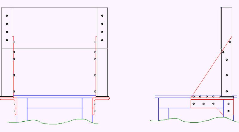
    Would any of you engineer-types on the forum care to comment on the rigidity of the machine design as it stands now? I’m trying to get the most rigidity possible with the materials and parts I have on hand with no welding. If anyone sees a better way to go about it (short of me spending yet more money) please sing out; I’m not a mech. engineer..

    The table is obviously very stiff but the machine on top needs to be stiff as well. The easy way to make the fixed bridge is to just bolt the two 3x3 vertical tubes straight to the table-top but I want more Y-travel than that allows. I have a 2 foot piece of 5”x5”x ½” angle iron that I plan to halve & bolt to the sides of the table frame & mount the vertical tubes on top of them. I have a 12”x18”x1/2” piece of flat stock I will cut diagonally to make 2 gussets to bolt to the inside faces of the vertical tubes & to the edge of the table top. The wider spacing of the verticals gives me enough spacing to use all of the available slide travel. I think the mount design for the verticals is strong enough. I’m worried a bit about the Y-axis slide mount plate though. I have a piece of 3/8”x12” plate to bolt to front face of the verticals but not enough to put a 2nd piece on the back face.

    In the drawing the table is shown in blue, the vertical tubes are black, the 5”x5” angles and ½” gussets are red, the 3/8” plate is gray. Keep in mind that bolted securely to the front of the 3/8” plate will be 2 - 25mm linear guide rails and a heavy duty linear stage/ballscrew assy that has a solid steel backbone that supports it’s own rails. I didn’t draw those in yet. They all should add considerable stiffness as well. I wish I could whip up one of those nice 3D renderings some of you guys do but you’ll have to make do with my crude 2D CAD sketch. It will be joined by drilling & tapping a zillion holes with a few dowels in selected areas. Opinions??


    Milton in Tennessee ya'll!


  10. #10
    Member
    Join Date
    Jun 2010
    Location
    Australia
    Posts
    4256
    Downloads
    4
    Uploads
    0

    Default Re: CNC bridge mill for cutting aluminum.

    Heavy steel is good, but I would prefer to see (quite) a few more bolts everywhere than are shown. Some dowels, reamed after bolting, would be an excellent idea too - as you mentioned.

    I know welding is really rigid, but so often the steel warps after the heat. So nicely machined steel with lots of bolts and dowels is a good way to go.
    On which subject - all mating faces need to be machined smooth. Mill finish would walk all over the place. What to do about the underside of the table where the angle is shown - awkward question. Going for the extra width might not be worth it after all.

    Whether it is best to have the gantry at one end, as shown, rather than in the middle, is another matter. You would need a really long overhang to get to the other end of the table, and that would worry me. Maybe I am a bit conventional?

    Cheers
    Roger


  11. #11
    Member
    Join Date
    Apr 2013
    Location
    Sweden
    Posts
    1899
    Downloads
    2
    Uploads
    0

    Default Re: CNC bridge mill for cutting aluminum.

    Quote Originally Posted by DICKEYBIRD View Post
    Would any of you engineer-types on the forum care to comment on the rigidity of the machine design as it stands now? I’m trying to get the most rigidity possible with the materials and parts I have on hand with no welding. If anyone sees a better way to go about it (short of me spending yet more money) please sing out; I’m not a mech. engineer..

    The table is obviously very stiff but the machine on top needs to be stiff as well. The easy way to make the fixed bridge is to just bolt the two 3x3 vertical tubes straight to the table-top but I want more Y-travel than that allows. I have a 2 foot piece of 5”x5”x ½” angle iron that I plan to halve & bolt to the sides of the table frame & mount the vertical tubes on top of them. I have a 12”x18”x1/2” piece of flat stock I will cut diagonally to make 2 gussets to bolt to the inside faces of the vertical tubes & to the edge of the table top. The wider spacing of the verticals gives me enough spacing to use all of the available slide travel. I think the mount design for the verticals is strong enough. I’m worried a bit about the Y-axis slide mount plate though. I have a piece of 3/8”x12” plate to bolt to front face of the verticals but not enough to put a 2nd piece on the back face.

    In the drawing the table is shown in blue, the vertical tubes are black, the 5”x5” angles and ½” gussets are red, the 3/8” plate is gray. Keep in mind that bolted securely to the front of the 3/8” plate will be 2 - 25mm linear guide rails and a heavy duty linear stage/ballscrew assy that has a solid steel backbone that supports it’s own rails. I didn’t draw those in yet. They all should add considerable stiffness as well. I wish I could whip up one of those nice 3D renderings some of you guys do but you’ll have to make do with my crude 2D CAD sketch. It will be joined by drilling & tapping a zillion holes with a few dowels in selected areas. Opinions??

    You should move the gantry forward just so much so that the spindle motor axis ends up in the center of the table. The beam should be moved about 1/3 into the middle, depending on your Z and spindle. If you keep it where it is now you will waste space and limit the work area. I think bolting is good, but I am not a mechanical engineer. Welding is better, but I would not start welding since welding is final, you have no chance of adjusting anything once it is welded. Also, welding may destroy everything since the heat may cause warping if you are not an expert in welding.

    https://www.youtube.com/c/AdaptingCamera/videos
    https://adapting-camera.blogspot.com


  12. #12
    Member DICKEYBIRD's Avatar
    Join Date
    Apr 2003
    Location
    Memphis
    Posts
    354
    Downloads
    0
    Uploads
    0

    Default Re: CNC bridge mill for cutting aluminum.

    Thanks for your input. This is a big project for me; I appreciate all advice!

    The location of the bridge is just approximate now as I'm still doodling with the Z-axis design at the moment. The X-2 mill head and it's mounting plate plus the slides & ballscrew gives it a larger offset than you'd think. It won't be too far from where it's shown on the drawing.

    Milton in Tennessee ya'll!


  13. #13
    Registered vegipete's Avatar
    Join Date
    Mar 2006
    Location
    Sol 3 (YVR)
    Posts
    202
    Downloads
    0
    Uploads
    0

    Default Re: CNC bridge mill for cutting aluminum.

    Can you take the vertical side posts all the way down to the lower frame cross members with suitable spacers to clear the edge of the table surface?


  14. #14
    Member DICKEYBIRD's Avatar
    Join Date
    Apr 2003
    Location
    Memphis
    Posts
    354
    Downloads
    0
    Uploads
    0

    Default Re: CNC bridge mill for cutting aluminum.

    Quote Originally Posted by vegipete View Post
    Can you take the vertical side posts all the way down to the lower frame cross members with suitable spacers to clear the edge of the table surface?
    Great idea Pete & somebody mentioned that on another forum. I'd have to buy 3"x3" stock long enough to do so & I'm committed to using the 2 - 26.5" long sticks I have in hand. I've blown my hobby budget already and am designing with what I have. Does the method I've shown look like it will be stiff enough? Aluminum & some wood is the planned work material.

    Milton in Tennessee ya'll!


  15. #15
    Member DICKEYBIRD's Avatar
    Join Date
    Apr 2003
    Location
    Memphis
    Posts
    354
    Downloads
    0
    Uploads
    0

    Default Re: CNC bridge mill for cutting aluminum.

    You know, that idea is sounding better & better. I'm going check around a bit tomorrow & see what the local price is on some longer sticks of 3" square. I found some 36" long pieces on ebay for around $85 incl shipping. Sure would save a lot of drilling & tapping in uncomfortable positions. I'll have to hide it from the missus though!

    Milton in Tennessee ya'll!


  16. #16
    Member DICKEYBIRD's Avatar
    Join Date
    Apr 2003
    Location
    Memphis
    Posts
    354
    Downloads
    0
    Uploads
    0

    Default Re: CNC bridge mill for cutting aluminum.

    Quote Originally Posted by RCaffin View Post
    Heavy steel is good, but I would prefer to see (quite) a few more bolts everywhere than are shown. Some dowels, reamed after bolting, would be an excellent idea too - as you mentioned.

    On which subject - all mating faces need to be machined smooth. Mill finish would walk all over the place. What to do about the underside of the table where the angle is shown - awkward question. Going for the extra width might not be worth it after all.

    Whether it is best to have the gantry at one end, as shown, rather than in the middle, is another matter. You would need a really long overhang to get to the other end of the table, and that would worry me. Maybe I am a bit conventional?
    Thanks Rog for warning me about the finish of the mating parts. That never crossed my mind, yet another time consuming but necessary chore. What about a roughing up the mating areas & applying a structural epoxy just before the final bolt up?

    The final position of the fixed bridge will be determined by the total "stack up" of the X-slide components. The spindle axis will be located at the center of the table & the moving X-table's movement will be equal in both directions.

    As suggested by Pete & others, I'm changing the design to incorporate longer vertical posts that bolt to the table legs with spacers. This will allow me to use my existing 3" square tubes to connect the posts and serve as mounts for the linear rails. With the addition of a 2" square tube placed across the junctions of the cross tubes it will be "Strong, like bull."

    Milton in Tennessee ya'll!


  17. #17
    Member
    Join Date
    Jun 2010
    Location
    Australia
    Posts
    4256
    Downloads
    4
    Uploads
    0

    Default Re: CNC bridge mill for cutting aluminum.

    What about a roughing up the mating areas & applying a structural epoxy just before the final bolt up?
    Well, not perfect, but it might help.
    The important thing is to get the surfaces clean of any mill scale etc. Perhaps a light touch with a belt sander, just enough to make them shiny but NOT enough to make the surfaces curved.
    The epoxy can do two things:
    * Prevent sideways movement - but the dowels should do that better
    * Prevent any rocking or twisting - the epoxy could certainly help there

    On which score: do NOT use Chinese fasteners. They are very soft and will deform or stretch. I have had to replace all critical Chinese bolts in some gear with branded ones from US, EU or AUS. Same applies to many Hex keys.

    Cheers
    Roger


  18. #18
    Member DICKEYBIRD's Avatar
    Join Date
    Apr 2003
    Location
    Memphis
    Posts
    354
    Downloads
    0
    Uploads
    0

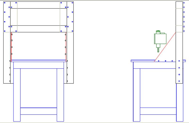
    Default Re: CNC bridge mill for cutting aluminum.

    OK, rev 1.01 36" vertical bridge posts with spacers between them & the table legs, 3" square tube (1/4" wall thickness) cross tubes, 3/8"x6" plates on back side joining vert posts & cross tubes, X-2 mill head shown in correct position, space between it & posts is correct, (space shown is total stack-up of 2, 25mm THK linear guides, 5/8" spindle mount plate and 5/8" x-axis mount plate) Oops, forgot to add 2" square (1/4" wall thickness) diagonal brace at the top. Some clarity left off such as the vertical post mount 5/16" SHCS bolts go through the inner face accessed through 1/2" holes drilled into the outer face, case-hardened washers installed from the bottom. All joints roughened with 80 grit Roto-Loc disc, cleaned with acetone. After final alignment & any needed shim placements verified, layer of structural epoxy added & all bolts torqued. Reamed holes & dowels at the important locations. Bottom of posts plugged, holes drilled in cross-braces & both filled with oiled sand. Should be OK, yes? If not please sing out!


    Milton in Tennessee ya'll!


  19. #19
    Registered vegipete's Avatar
    Join Date
    Mar 2006
    Location
    Sol 3 (YVR)
    Posts
    202
    Downloads
    0
    Uploads
    0

    Default Re: CNC bridge mill for cutting aluminum.

    Somehow I find that upper cross tubes/back plates/diagonal structure ... disturbing. It doesn't give me a gut feeling of sturdy. But without welding, I'm not sure what would satisfy my gut. ;-)

    Could you change the two 3/8 plates and diagonal to a single full width plate on the front? Thickness, oh, maybe 1/4 or even just 3/16th? And add large tie rods through the cross tubes holding everything tight together?

    Perhaps 1/2" thick by about 2.5" square pucks to bolt to the inside faces of the vertical posts to locate the cross tubes, along with the tie rods, would be effective yet fairly simple.


  20. #20
    Registered vegipete's Avatar
    Join Date
    Mar 2006
    Location
    Sol 3 (YVR)
    Posts
    202
    Downloads
    0
    Uploads
    0

    Default Re: CNC bridge mill for cutting aluminum.

    CNC bridge mill for cutting aluminum.-untitled2-png
    Cross tube/vertical post junction. Tie rod in green. Blue puck must be securely bolted to vertical post. Perhaps assemble the parts with fasteners fairly snug, lay it on your beautiful ground table and whack with a rubber mallet to set everything flat and aligned, then remove the tie rods to disassemble, without disturbing the pucks, and pin/dowel the pucks into place.


Page 1 of 2 12 LastLast

Tags for this Thread

Posting Permissions

  • You may not post new threads
  • You may not post replies
  • You may not post attachments
  • You may not edit your posts
  •  


About CNCzone.com

    We are the largest and most active discussion forum for manufacturing industry. The site is 100% free to join and use, so join today!

Follow us on


Our Brands

CNC bridge mill for cutting aluminum.

CNC bridge mill for cutting aluminum.