Ian
I should have elaborated. I have a cheap chinese mill/drill that has a mt3 or similar taper and I hate it. Despite being anal about over tightening things Its forever getting stuck so you have to wack it pretty hard to get it to release which puts a hell of a lot of load on the bearings. I understand that you want to modify the tooling by shortening the taper and adding a stop ring on the bottom and it will probably work just fine Im just imagining it being rather fiddly to get the ring set in the right place and then make sure it dosnt move when tightened up against the spindle. In my mind it will always be a drill taper
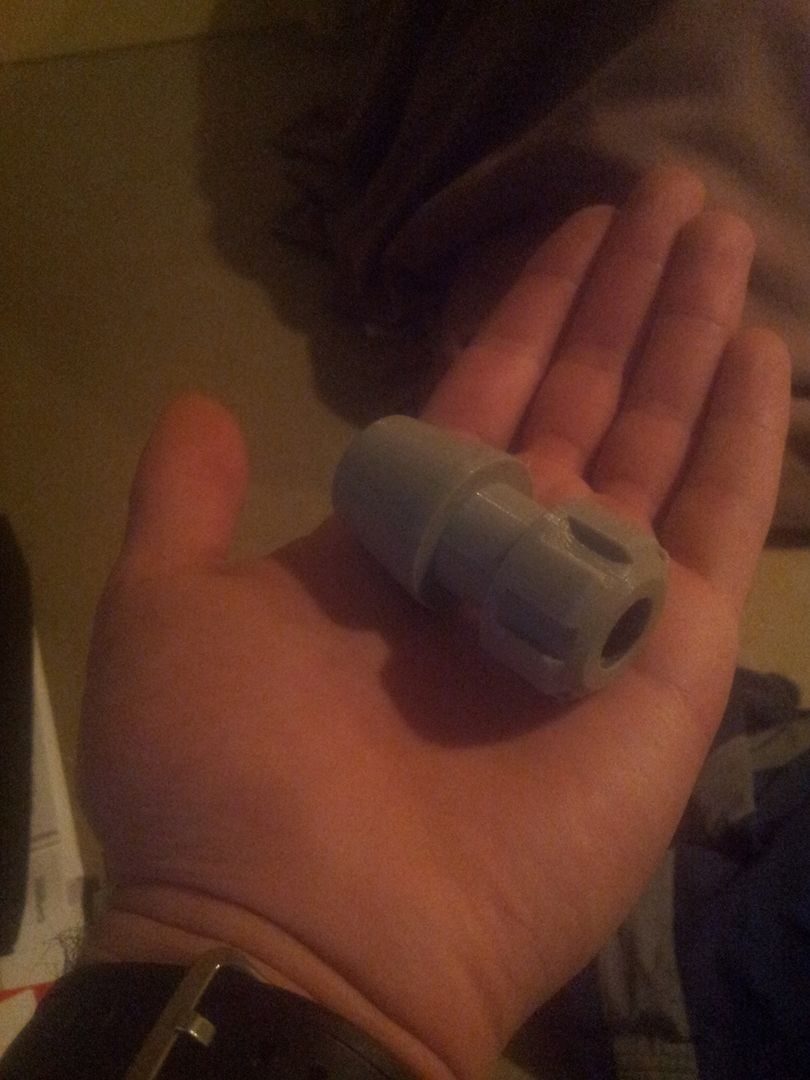
Ill post a pick of a 3dprinted mockup I did of the tooling I plan to use when I get a chance. Also I have a plan to keep the pneumatics for the power drawbar fixed on the left side of the machine so the x and z axis wont need to carry the weight. The spindle will just go to its tool change position and in doing so kind of slide into the pdb assembly then release the tool.
Yea easily I could probably go up to 10kg if i really had to but that would effect the inertia and slow it down more than im prepared to. I am planning to use nema 34 motors though so it might be ok
EDIT
Just imagine a pull stud in the far end. Btw sorry my camera is so crap


 Reply with Quote


