Solid Bench Top Mill Build (warning large photos) - Page 2


Page 2 of 14 FirstFirst 1234512 ... LastLast
Results 21 to 40 of 272

Thread: Solid Bench Top Mill Build (warning large photos)

  1. #21
    Member handlewanker's Avatar
    Join Date
    Sep 2006
    Location
    Australia
    Posts
    6463
    Downloads
    0
    Uploads
    0

    Default Re: Solid Bench Top Mill Build (warning large photos)

    Hi, that is definitely a huge piece of metal.......nice to have the machinery to do that work even if it's going to peter out in a month.

    I invested $3,000 in a Bridgeport some years ago when our firm downsized the tool room and let a half dozen 'Ports go to the dealers.....after I was retrenched in the late 90's my new employer mate took a fancy to it and I sold it to him, re-investing in an Ajax mill, which is 1 1/2 times the size of the 'Port, similar to a King Rich, but it has a gearbox built into the knee and feeds and fast travers to all axes etc, so eventually I'll be machining the various bits and pieces.

    BTW, the Multiplaz is a powerful piece of kit, soon to replace the Mig, stick and Tig outfit I've been using....... I've been using it for the last 4 years now and the other gear is now redundant, so it'll get sold off on EBAY.

    I have doubts about that motor as it has to run for hours at a time under CNC conditions.......also the power required is 37 volts at 80 amps......that's a big transformer, and I believe the motor runs very hot.

    A 600 watt power supply for 48 volts at 12.5 amps on EBAY costs something like $125, so you'd need 5 times that.

    The spindle drive has been a thorn for me as they don't come cheap......making the spindle is a straight forward design with two angular contacts at the bottom and a pair of radials at the top etc, but the motor is the problem.

    I've got a 3/4 hp 3,000 rpm 3 phase motor that I wanted to use, but the weight hanging on the Z axis slide is going to be an issue.......early days yet, so I'll wait until it get to that stage.
    Ian.


  2. #22
    Registered
    Join Date
    Jan 2011
    Location
    New Zealand
    Posts
    80
    Downloads
    0
    Uploads
    0

    Default Re: Solid Bench Top Mill Build (warning large photos)

    The proper bridgeports are pretty nice but this is a cheap chinese clone. Tbh I wouldnt take it if they gave it to me but it does the job so cant really complain.
    I do have doubts about the motor also but im struggling to find any other options. I have no problem powering it as i have 4 server power supplies which each put out 12V at 82A. Im going to use two of them in series to get 24V but can add another one for 36v if i need more rpm.

    With regards to heat thats something I no idea on. I had assumed that seeing as the motor windings have a very low resistance (0.03ohms) that there wouldnt be much heat coming from it. Im not sure what maths are involved to work it out tbh. If im feeding the motor 2000w of power and the motor is 80% efficient then 400w would be dissipated as heat which thinking about it is quite a lot. This is a very simplistic way of thinking about it so i could be way off.

    Id be rather keen to make a spindle from scratch but the need for hardening and grinding is putting me off a little. If i had access to a cylindrical grinder id be all for it


  3. #23
    Member handlewanker's Avatar
    Join Date
    Sep 2006
    Location
    Australia
    Posts
    6463
    Downloads
    0
    Uploads
    0

    Default Re: Solid Bench Top Mill Build (warning large photos)

    Hi, when it comes to the crunch, the last link in the chain is the spindle motor.........everything else can be made or assembled from off the shelf items, but the motor just doesn't get small, compact and powerful in any that I've seen.

    I've ruled out using a conventional router or any other wood tool that has brushed motors as the power source......brushes are out......and any 3 phase synchronous motor is way too heavy.

    It has to be a BLDC type to get the speed range and power output in a compact package without the weight problem, so perhaps it's going to be a China solution in the end.

    I'd settle for a 3,500 rpm 800- 1000 Watt motor for the machine I'm building, and adjust the torque/speed needs with belts etc.
    Ian..


  4. #24
    Member
    Join Date
    Mar 2009
    Location
    New Zealand
    Posts
    39
    Downloads
    0
    Uploads
    0

    Default Re: Solid Bench Top Mill Build (warning large photos)

    I 'm watching this with interest please keep those pictures coming.
    These links may be of interest,showing the implementation of similar spindle idea and interesting atc.

    CONVERSION: X3 mill with rails, ATC, new motor

    Build Log: Servo Drive and VFD with vector control

    I have considered this idea myself and seen it used but not at the power level you are thinking.I note he rewinds the motor
    probably to allow higher input voltage for greater efficency,as the app doesnt limit you to batteries.This would reduce current draw to.
    Possible issues include the lack of high speed cooling air,motor not designed for continuous operation,noise,torque ripple
    at low speeds,controllers not designed for this app,a bit of maths for 3 server power supplys : 3 x 82 x 12 = 3kw or the maximum motor power.
    Also start up is a problem.The cold motor winding are probably at 1/10th of there working resisistance. So massive
    inrush current x10 normal at least.Not sure how these problems are overcome,soft starting maybe.

    How much power do you need for what you want to machine? Maybe thats the what you need to know first(from an
    online calculator) then work back to motor and ps requirements.

    For eg portal mills the bridge and legs are cast as one piece.Alignment is by 3 screws placed at the outer edges
    of the legs(forming a triangle).As long as your centre of mass falls within the triangle you can adjust for alignment;
    in both axis .Grout or epoxy contained by an o-ring secures the position.Alignment finishing before setting.
    This method would seem to provide considerable leeway in parts precision,less being preferred of course.
    I havent investigated it but loctite but may have a product for this app suitable for steel.Machined surfaces
    are probably the ideal of course,but without machine tools its the method I would use.


  5. #25
    Member handlewanker's Avatar
    Join Date
    Sep 2006
    Location
    Australia
    Posts
    6463
    Downloads
    0
    Uploads
    0

    Default Re: Solid Bench Top Mill Build (warning large photos)

    Hi Shedbob, thanks for the link to the X3 rebuild by Jonathan.......that man has put a lot of work into his build.

    The X3 has always been a popular donor for CNC retrofitting, and the method of removing the sides of the doveetails and fitting solid steel bars to mount the linear rails on is brilliant.

    Just milling the dovetails off totally would not work as it weakens the casting etc, and fitting linear rails to the flat part of the casting when the dovetail side is removed also would not work as you'd need side clearance for the bearing blocks.

    I have a small jig borer and the Z axis has dovetails to position the head......the main Z movement being with a quill, which has a short travel and is not practical.......so the solution to fitting linear rails to the head and column is now a simple matter of a bit of machining to the column and head dovetails and fitting long steel flat bars etc.

    I put this one at the far side of the back burner when I contracted to buy a complete CNC mill package from SKYFIRE.COM, now almost at the shipping stage.

    I was especially interested in the remake/rewind of the spindle motor......it seems almost a simple DIY project provided the donor motor is available and the NDM magnets too.

    If my memory serves me well, Jonathan did say that a large stepper motor could be run from a VFD in 3 phase mode, by connecting the two pole windings together and using the centre point and winding ends as the 3 phase input point.

    I wonder if the largest Nema 45 stepper could be used as a spindle drive, or possibly two motors side by side to a common pulley on the spindle?

    The weight would probably approach that of a small 3 phase motor, so no gain there.
    Ian.


  6. #26
    Registered
    Join Date
    Jan 2011
    Location
    New Zealand
    Posts
    80
    Downloads
    0
    Uploads
    0

    Default Re: Solid Bench Top Mill Build (warning large photos)

    Quote Originally Posted by shedbob View Post
    I 'm watching this with interest please keep those pictures coming.
    These links may be of interest,showing the implementation of similar spindle idea and interesting atc.

    CONVERSION: X3 mill with rails, ATC, new motor

    Build Log: Servo Drive and VFD with vector control

    I have considered this idea myself and seen it used but not at the power level you are thinking.I note he rewinds the motor
    probably to allow higher input voltage for greater efficency,as the app doesnt limit you to batteries.This would reduce current draw to.
    Possible issues include the lack of high speed cooling air,motor not designed for continuous operation,noise,torque ripple
    at low speeds,controllers not designed for this app,a bit of maths for 3 server power supplys : 3 x 82 x 12 = 3kw or the maximum motor power.
    Also start up is a problem.The cold motor winding are probably at 1/10th of there working resisistance. So massive
    inrush current x10 normal at least.Not sure how these problems are overcome,soft starting maybe.

    How much power do you need for what you want to machine? Maybe thats the what you need to know first(from an
    online calculator) then work back to motor and ps requirements.

    For eg portal mills the bridge and legs are cast as one piece.Alignment is by 3 screws placed at the outer edges
    of the legs(forming a triangle).As long as your centre of mass falls within the triangle you can adjust for alignment;
    in both axis .Grout or epoxy contained by an o-ring secures the position.Alignment finishing before setting.
    This method would seem to provide considerable leeway in parts precision,less being preferred of course.
    I havent investigated it but loctite but may have a product for this app suitable for steel.Machined surfaces
    are probably the ideal of course,but without machine tools its the method I would use.
    Hi Shed
    I had seen those links before but hadnt saved them so thanks for posting them.
    Have you got a link to a calculator for power requirements? Could be rather useful. Even if I only run the motor around 1000watts that puts it in similar power levels as the tormach mills. I figure its not going to be pulling anywhere near 80A all of the time so heat build up shouldn't be a massive issue but i could be very wrong. Initially I was just going to use an rc speed controller to start with until I found a better solution i.e. rewinding and using one of Jonathans controllers but thats something ill look at further when I get to that stage.
    I had considered having three setscrews and grouting the joints but I am machining all mating surfaces so i might just shim it for final adjustments.


  7. #27
    Registered
    Join Date
    Jan 2011
    Location
    New Zealand
    Posts
    80
    Downloads
    0
    Uploads
    0

    Default Re: Solid Bench Top Mill Build (warning large photos)

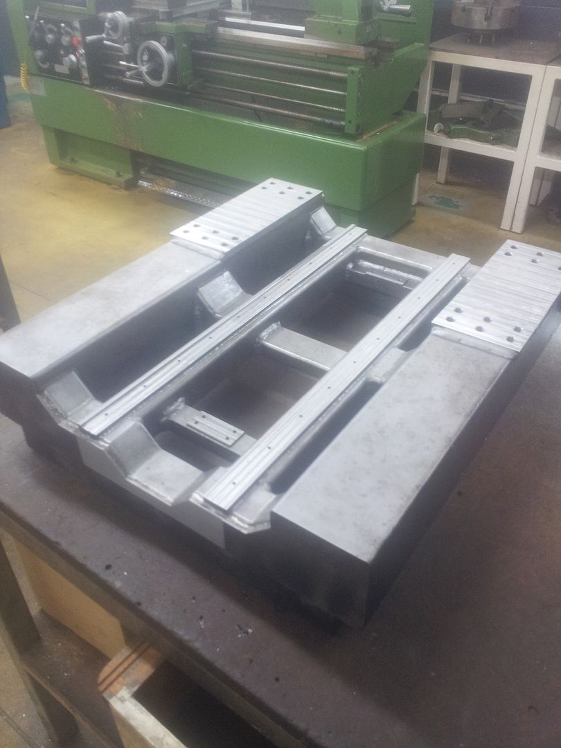
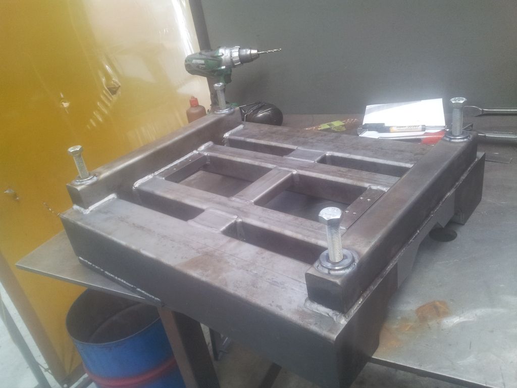
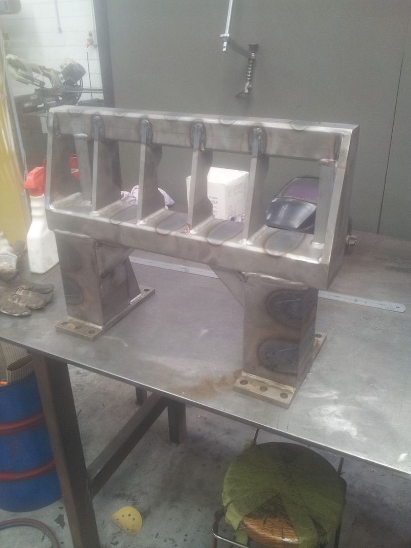
    Ive finished machining the lower frame so Ive started working on the upper section. I also welded some bosses on the bottom for feet. I was trying to get some parts laser cut from 10 and 12mm plate but it dosnt look like anyone wants to even try cutting anything that think. Ive had to start making them myself which i didnt really want to do due to time constraints but it looks like my only option.


  8. #28
    Member handlewanker's Avatar
    Join Date
    Sep 2006
    Location
    Australia
    Posts
    6463
    Downloads
    0
    Uploads
    0

    Default Re: Solid Bench Top Mill Build (warning large photos)

    Hi, looking more like an iron casting by the day......that's a pretty solid build.......have you had it sand/shot blasted to give it that overall grey finish?

    One question......how are you going to align the two X axis rails.....they have to be dead true to one another in 2 planes.

    This is usually done after the complete bridge is welded up and then machined on the two rail seats as a whole.

    Forget that question......It looked like the linear rails were already bolted to the separate pieces before the welding.

    I'd be interested to see the Z axis slides layout design, as this is always the weak link in a gantry type machine, being that it hangs down below the bridge when fully extended.......any bulk in that area of the build also makes it stand out from the bridge face too adding cantilevering forces against the X axis saddle.

    Last question......what are you planning for a table?
    Ian.


  9. #29
    Registered
    Join Date
    Apr 2012
    Location
    VietNam
    Posts
    72
    Downloads
    0
    Uploads
    0

    Default Re: Solid Bench Top Mill Build (warning large photos)

    The Y axis looks pretty solid to me while the X axis look a little bit weaker than I expected. Is steel really expensive where you live?. I wish that the shipping cost is free then I could send you some . I would like to make the passive parts heavy and solid while the active parts are solid and light as possible.
  10. #30
    Member handlewanker's Avatar
    Join Date
    Sep 2006
    Location
    Australia
    Posts
    6463
    Downloads
    0
    Uploads
    0

    Default Re: Solid Bench Top Mill Build (warning large photos)

    Hi, I think with this size build the table would not be as big and heavy as a comparable column milling machine, so if a conventional CNC column mill works very smoothly on linear rails with it's large cast iron table, then this one with a table of say 50mm thick steel plate and a work area of only 300mm X 300mm approx. will be much easier to move in the rapids etc.

    Cutting Tee slots in a steel table would not be a job to be taken lightly.....probably a send out job, but even then it would probably be cheaper than a machined iron casting.

    With this problem of the Tee slot cutting in my build, I toyed with the idea of welding one together from pre milled Tee shaped lengths of steel and then machining all over. but the table I want is 500mm long X 250mm wide and approx. 30mm thick..........I can get one like that by canabalising a co-ordinate XY table for about $300-$400 at our local machinery dealer, and sell off the rest of the slides and base on EBAY.

    The welding path appeals to me more as it can be DIY made by milling slots in pieces of steel and welding them top and bottom to form a table of whatever width you need.
    Ian.


  11. #31
    Registered
    Join Date
    Jan 2011
    Location
    New Zealand
    Posts
    80
    Downloads
    0
    Uploads
    0

    Default Re: Solid Bench Top Mill Build (warning large photos)

    Quote Originally Posted by handlewanker View Post
    Hi, looking more like an iron casting by the day......that's a pretty solid build.......have you had it sand/shot blasted to give it that overall grey finish?

    One question......how are you going to align the two X axis rails.....they have to be dead true to one another in 2 planes.

    This is usually done after the complete bridge is welded up and then machined on the two rail seats as a whole.

    Forget that question......It looked like the linear rails were already bolted to the separate pieces before the welding.

    I'd be interested to see the Z axis slides layout design, as this is always the weak link in a gantry type machine, being that it hangs down below the bridge when fully extended.......any bulk in that area of the build also makes it stand out from the bridge face too adding cantilevering forces against the X axis saddle.

    Last question......what are you planning for a table?
    Ian.
    Hi Ian
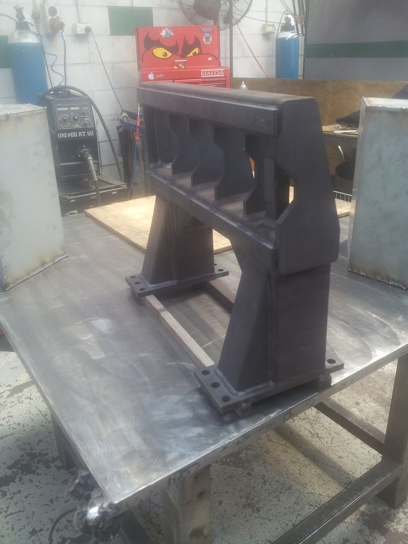
    Yes Ive been bead blasting the parts prior to welding as I find its the quickest method to get all of the grease/ oil and mill scale off.
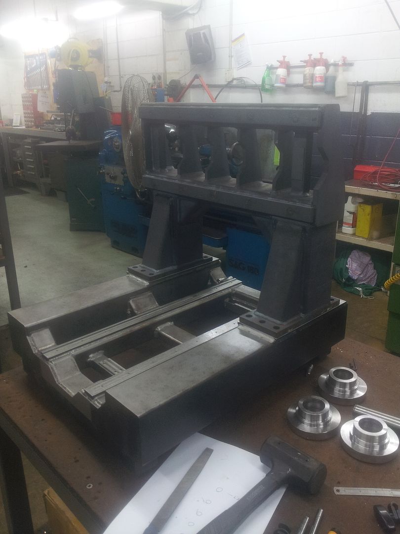
    You're right they will be machined after welding, Ill update the thread with some photos which should make things clearer.
    Ill try to post some detail photos of the z assembly but this is a work in proces so it might change by the time I get to making it. I dont like the z axis set up on gantry mills either but I havent managed to come up with a better solution as of yet.
    I had been planning to make the table out of ally or steel with a bunch of threaded holes like a fixture plate to avoid the need for t slots

    Quote Originally Posted by khoac3 View Post
    The Y axis looks pretty solid to me while the X axis look a little bit weaker than I expected. Is steel really expensive where you live?. I wish that the shipping cost is free then I could send you some . I would like to make the passive parts heavy and solid while the active parts are solid and light as possible.
    What part of it looks weak to you? The model I first posted has been reinforced since then


  12. #32
    Registered
    Join Date
    Jan 2011
    Location
    New Zealand
    Posts
    80
    Downloads
    0
    Uploads
    0

    Default Re: Solid Bench Top Mill Build (warning large photos)

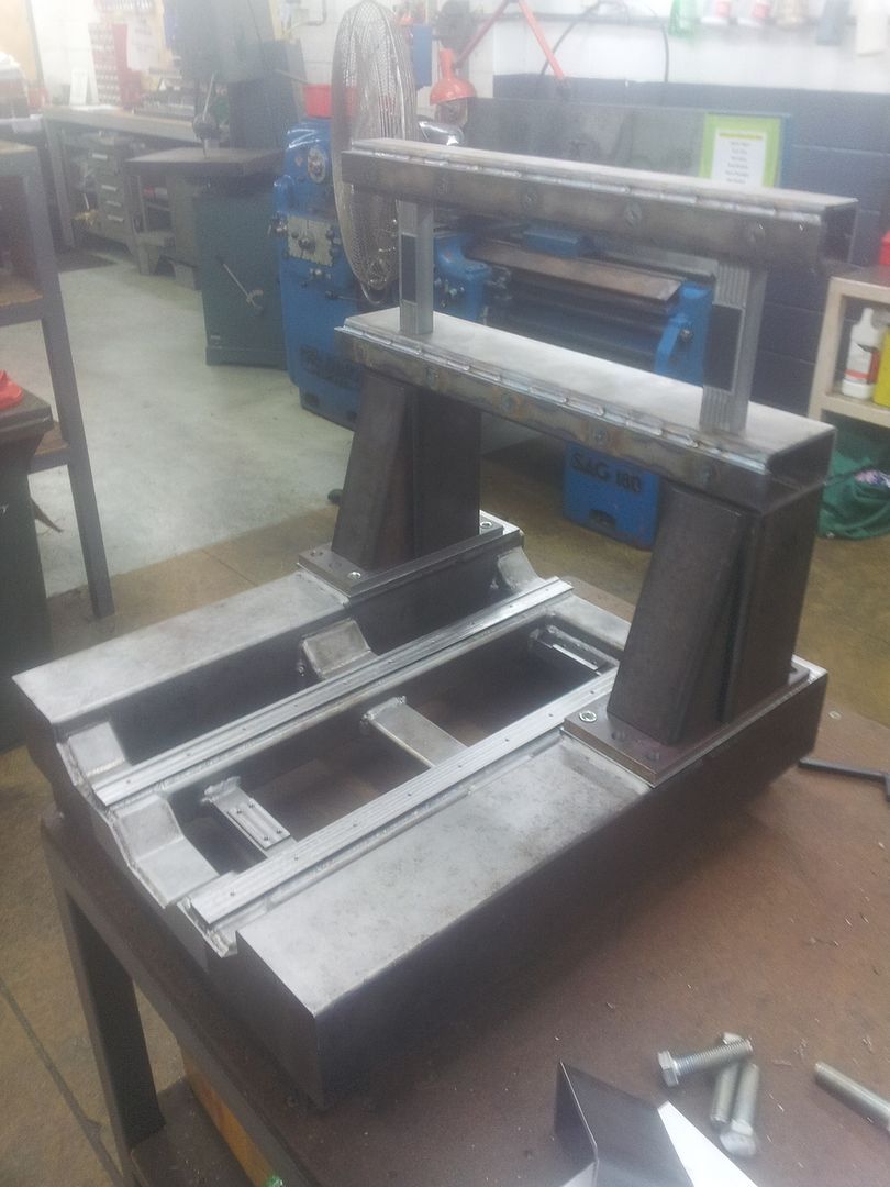
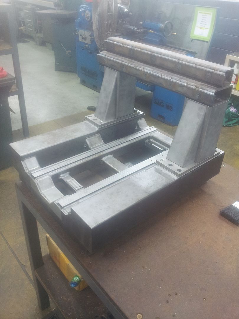
    Update time
    The upper section has been fully welded and stress relieved. The stripes you see along the vertical and horizontal rhs are form having to heat straighten everything after welding as the legs moved in about 2mm so the bolt holes didnt line up as well as I would have liked.


  13. #33
    Registered
    Join Date
    Jul 2011
    Location
    New Zealand
    Posts
    11
    Downloads
    0
    Uploads
    0

    Default Re: Solid Bench Top Mill Build (warning large photos)

    Looking great. I never solved my spindle issue. Still using a Chinese 800W spindle that I have replaced the bearings on. The new ones have lasted longer, but I am gentler than I need to be. Looking forward to seeing what you come up with. The great thing about such a small machine is that you can use very high acceleration because you have less mass, but because the spans are short, it is very rigid.


  14. #34
    Member handlewanker's Avatar
    Join Date
    Sep 2006
    Location
    Australia
    Posts
    6463
    Downloads
    0
    Uploads
    0

    Default Re: Solid Bench Top Mill Build (warning large photos)

    Hi......reinforced???.....that is a major redesign....awesome in it's sheer strength.....I doubt that will move under cutter loading.

    If you're after a piece of aluminium for the table, there's a slab 500 X 250 X 50 going on Ebay at the moment, just been relisted at $200.

    I think ally will eventually be a headache as it's soft and easily damaged from bolting and job loading.

    In this build (and the one I'm on) I don't think the weight of the table is a drawback as it runs on balls...linear rails.... and that is as smooth and virtually friction free as you can get.......inertia from the mass not considered too important.

    If you use tapped holes, the problem of continuous swarf clearing is always a headache, unless you use plastic plugs for the unused holes etc.

    I'm thinking of parallel holes and using something like the Dynabolts design to do the work holding.

    This method would use the expansion and grip of the bolt body in the parallel hole to hold the job down.

    At any rate, I think an ally table would soon show signs of wear, so I'll probably go for a steel slab 25mm thick and either use tapped holes or the parallel type.....early days yet.

    As Tee slots are a desirable way to hold things down, I've considered making a tee slot table from 30mm X 40mm hot rolled........ NOT COLD ROLLED OR BRIGHT MILD STEEL..... steel bars, milled with a 10mm wide slot, 15mm deep on both sides of the 40mm wide side, and placed side by side and welded longitudinally top and bottom.

    The bars on the outside edges of the table are milled with only one slot etc,

    One side of the slot is half milled away so that when the slots are placed side by side they form a natural tee shape.

    You'd need 8 steel bars 30 X 40 and 300 long.....2.4 metres of steel..... to make a table 300mm long X 320mm wide X 30mm thick......depending on the steel stock sizes.

    Welding down in the middle of the bottom of the slot and underneath too for 300mm long would be fairly easy, and provided the welding was done progressively no problems and minimal distortion should occur, it would only need a minimum clean up top and bottom afterwards.

    As you can guess, I'm not a big fan of machining Tee slots in the solid material, but a composite build gives you the same result.
    Ian.


  15. #35
    Registered
    Join Date
    Jan 2011
    Location
    New Zealand
    Posts
    80
    Downloads
    0
    Uploads
    0

    Default Re: Solid Bench Top Mill Build (warning large photos)

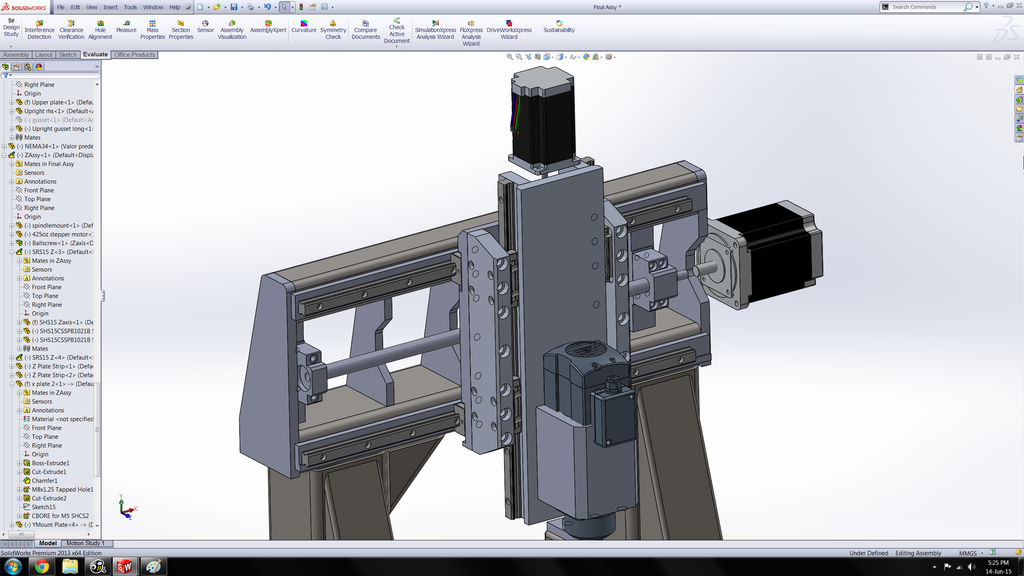
    I was originally planning to use ally but I think your right, extra weight on the y axis really dosnt effect much as its unlikely to be heavier that the x/z assembly. Might see if i can find some 30mm steel plate.
    On a fixture plate the holes are often filled with grub screws which isnt perfect but its better than nothing.

    Some welding fixture tables use that kind of system. The one I saw I think used ball bearings that splayed out when they were all the way through the plate. Might give you some ideas if you can find it.

    Id never thought machining Tslots would be that difficult provided you have a mill with power feed. Otherwise i can imagine your arm might get sore lol

    Btw
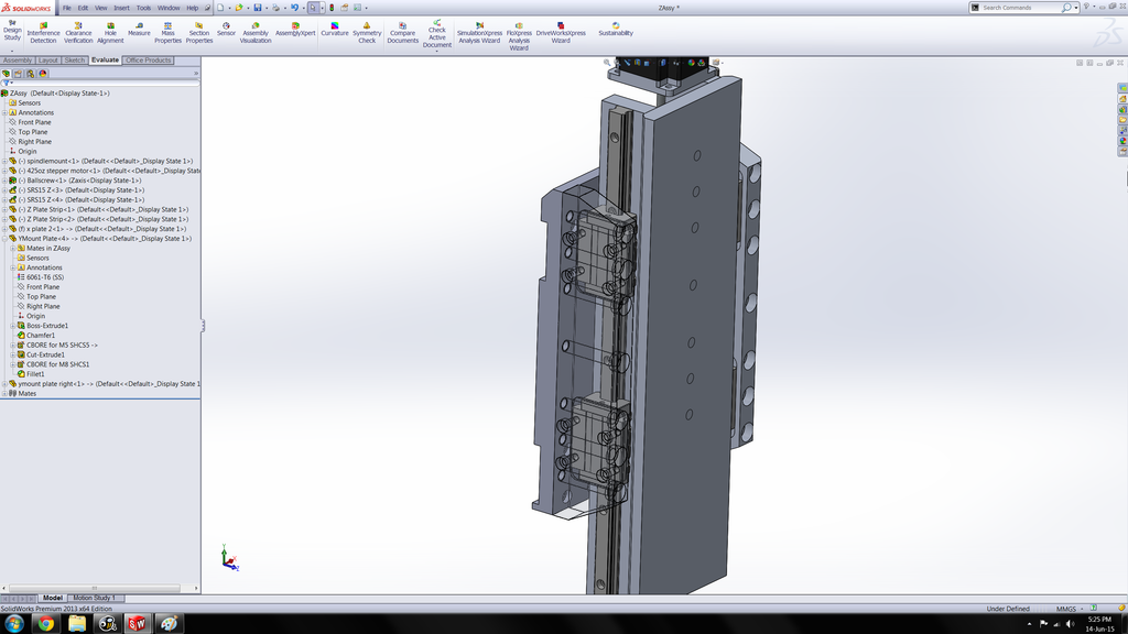
    This is the currently plan for the z axis. Keep in mind the design isnt quite finished but please let me know if you can see any weak points in it


  16. #36
    Registered
    Join Date
    Jul 2011
    Location
    New Zealand
    Posts
    11
    Downloads
    0
    Uploads
    0

    Default Re: Solid Bench Top Mill Build (warning large photos)

    That z design looks good. Can't think of a way to make it more rigid than what you have.


  17. #37
    Member handlewanker's Avatar
    Join Date
    Sep 2006
    Location
    Australia
    Posts
    6463
    Downloads
    0
    Uploads
    0

    Default Re: Solid Bench Top Mill Build (warning large photos)

    Hi, I can't really envisage the layout as far as attaching it to the base part of the X axis saddle, but mounting the bearing blocks on the sides will give you less stick out or overhang from the X axis rails etc....all to the good......aligning them to be perfectly spaced and parallel in two planes will tax your ability.

    I've opted to have more slide length (at the moment) above the Z axis travel to cut down on the hang down amount.......having only 135mm of total clearance under the bridge when the Z axis slide is all the way up etc.

    A lot depends on the work load you're going to push against the cutter, and if it's steel that will ,impact on the Z axis when it hangs down......unlike a column mill that is fully supported all the way down.

    Mostly, CNC machining is many cuts at a small DOC, unlike conventional milling that depends on maximum metal removal per cutter setting....very time consuming and totally operator hands on intensive.

    You won't get a torsional twisting on the X axis rails as with your build design they're practically bomb proof, so it all hinges on the Z axis to resist back and forward movement when it's at full down travel.

    Having said that, I would look at the configuration of the slides on the sides for back and forward resistance as opposed to having them on the face of the Z axis as in conventional set-ups.

    With that side mounting design I think that spacing the bearing blocks even further apart would pay dividends as you can go up more with a longer slide length and still have rigidity without hanging down.

    I've got an old capstan lathe that I used in another life for a business project, and the cross slide has a long narrow slide aspect ratio......this enable it to plunge a form tool 25mm wide into a piece of steel without deflecting and digging in......this is due to the support from the long cross slide dovetails.

    In the Z axis you have, there is no support once the slide is down and out of the bearing blocks, so you'll need more body to the actual moving member to resist deflection........my opinion would be to be narrower and deeper in section, even at the expense of increased distance from the X axis rails.......a wider thinner slide has less resistance to bending forces than a narrower thicker one......more like a ram than a sliding flat plate.

    Seeing your design for the Z gives me more ideas for the Z axis I'm working on, as in mine, with the bearing blocks on the front of the saddle face means the spindle is sticking out a lot more than I'd like to have it from the X axis face.

    The cheap 3040 and 6040 ally routers on EBAY solve that problem by having a solid ally block with round linear rails inside on either side of the screw.......they also have much less travels and clearance under the gantry.

    BTW, I've just sketched the Tee slot table design I'd like to have.......500mm long X 250mm wide and 40mm thick, working area only of 300 X 250.....the longer length to cater for mounting a 4th axis and tailstock on the ends etc.

    I reckon that with three 60mm X 40mm X 500mm flat hot rolled steel bars laid side by side with two more 40 X40 at each side, all welded together longitudinally top and bottom, having been previously milled to give the Tee slots etc, will give a table that requires only minimal machining top and bottom after welding.

    I feel dubious about the method with tapped or parallel holes......it will work, but with further deep thought, tee slots are highly desirable if they can be achieved, and simple pre milling the bars can give just that.

    It would give you a tee slot 20mm wide X 25mm deep, having the bottom width at 35mm and 10mm deep for the tee nut or tee bolt head, which still gives you 15mm solid steel between the bottom of the tee nut and the table to mount the bearing blocks to.
    Ian.


  18. #38
    Member handlewanker's Avatar
    Join Date
    Sep 2006
    Location
    Australia
    Posts
    6463
    Downloads
    0
    Uploads
    0

    Default Re: Solid Bench Top Mill Build (warning large photos)

    Hi, here's a quick sketch of how I'd build the table.....it's only 250mm wide, but to go to 300mm wide needs only another 60mm piece of steel bar milled both sides.

    The bars are pre milled on both sides, only one side on the ends, with simple slots, chamfered for weld preparation and subsequently welding top and bottom which is also straight forward...... precautions to keep the bars flat to prevent bowing is needed, but I would weld progressively back and front alternately etc making sure the assembly stayed cool by quenching it frequently to prevent expansion form locking in stresses etc.

    Ignore the first sketch as it was a doodle to explore the possibilities of fabrication and got added by mistake.
    Ian.

    Attached Thumbnails Attached Thumbnails Solid Bench Top Mill Build (warning large photos)-tee-slot-table-fabrication-jpg   Solid Bench Top Mill Build (warning large photos)-tee-slot-table-fabrication-jpg  
    Last edited by handlewanker; 06-14-2015 at 04:51 AM.


  19. #39
    Registered
    Join Date
    Apr 2012
    Location
    VietNam
    Posts
    72
    Downloads
    0
    Uploads
    0

    Default Re: Solid Bench Top Mill Build (warning large photos)

    Oh No. It looks good to me now. Pretty solid machine. Well done!


  20. #40
    Member handlewanker's Avatar
    Join Date
    Sep 2006
    Location
    Australia
    Posts
    6463
    Downloads
    0
    Uploads
    0

    Default Re: Solid Bench Top Mill Build (warning large photos)

    Hi, when you get a spindle solution I'll be watching as this is one nut that's hard to crack.
    Ian.


Page 2 of 14 FirstFirst 1234512 ... LastLast

Tags for this Thread

Posting Permissions

  • You may not post new threads
  • You may not post replies
  • You may not post attachments
  • You may not edit your posts
  •  


About CNCzone.com

    We are the largest and most active discussion forum for manufacturing industry. The site is 100% free to join and use, so join today!

Follow us on


Our Brands

Solid Bench Top Mill Build (warning large photos)

Solid Bench Top Mill Build (warning large photos)