Wiring help!


Results 1 to 15 of 15

Thread: Wiring help!

  1. #1
    Registered
    Join Date
    Jul 2011
    Location
    United States
    Posts
    36
    Downloads
    0
    Uploads
    0

    Default Wiring help!

    Hey Guys,

    I bought a G9036 in September and I'm getting ready to convert it over to CNC. I have most of my electrical components but I'm trying to lay out the wiring and I'm lost.

    This is the first time I have tried to do this and I'm not sure I understand what all of the things mean.

    I bought the following:

    Main Board
    C11G

    Drivers (3 total)
    203V Geckodriver

    Motors (3 total)
    NEMA 32 1200 oz-in motors

    Power Supply
    Antek PS15N70R5

    I'm looking at making small production runs on some parts. So, I need to get this up and running in the next month or so. I'm planning on upgrading the motor in the lathe and using a VFD.

    Any recommendations on a VFD would be greatly appreciated. I'm thinking about upgrading to a 3 or 5 hp motor (I will be cutting stainless).

    In addition to the motor swap, I will be making a turret that will hold probably 6 tools (that’s the reason for the 3rd motor).


    Ok, so, on the power supply, I’m going to be wiring it for 110v. When I talked to Antek, they said it doesn’t really matter if I wire it 110 or 220. Since the computer and everything else is 110, I figured it would be easier to keep everything the same voltage.

    On the power supply outputs, I’m thinking I need to wire the X on one of the 70 volt outputs and the z on the other. Then wire the tool changer in parallel with the X output. I’m assuming there is really no reason to ever do a tool change and motion on the x axis at the same time. Do I need to wire in a circuit breaker on these outlets or just wire them directly? (I’m assuming directly)

    For the 5volt outlet, does it need a fuse between the power supply and the C11G?
    As said as this sounds, I’m not 100% sure which port to connect the power supply to on the C11G? The manual I have for the C11G is quite confusing to me and I figured it was better to stop and ask questions before letting the smoke out.

    Can anyone walk me though how to wire the C11G? I did a search and I didn’t anything with a C11G. I found a few C10’s but I’m not sure they are the same. If you know of a link, that will work too. I just don't want to screw anything up.

    Any help is greatly appreciated

    Similar Threads:


  2. #2
    Registered
    Join Date
    Jul 2011
    Location
    United States
    Posts
    36
    Downloads
    0
    Uploads
    0

    Default

    The other question I had, when making the cabinet for the electronics, what type of spacer should I use to space the C11G board above the heat sink? The soldered ends hand out below the board, so I need to space them up.

    As far as the cabinet, I’m doing back and forth between water cooling the heat sinks and using a couple of fans. How dust sensitive are the electronics? If I use the fans, I’m going to run the air through a filter, but I do a fair bit of metal sanding and my shop can get pretty dusty.


  3. #3
    Registered
    Join Date
    Apr 2007
    Location
    New York, NY
    Posts
    521
    Downloads
    0
    Uploads
    0

    Default

    Power supply should have two output wires. One is +70 VDC one is 0 VDC. Look at PS datasheet or ask manufacturer to figure out how to hook this up.

    Power supply output gets star wired to Gecko drives ie each drive has two wires that go directly to the power supply. I believe fuses are permitted. Check Gecko site for info. Geckos may have internal fuse.

    Does C11G require external power?

    There are insulated standoffs to space board off the enclosure. I've used a stack of nylon washers. Also be aware of the fastener shorting the board to the enclosure.


  4. #4
    Registered
    Join Date
    Jul 2011
    Location
    United States
    Posts
    36
    Downloads
    0
    Uploads
    0

    Default

    Quote Originally Posted by will gilmore View Post
    Does C11G require external power?
    Yeah, there is a 5 volt input for the board and a 12 volt for the VFD.

    I think I have most of the outputs figured out. Now I'm working on laying out the inputs. I'm not 100% sure on how to wire the inputs via a switch. The manual mentions switches with 12 volts, but the board says 5. So, I'm a little lost.


  5. #5
    Registered
    Join Date
    Apr 2007
    Location
    New York, NY
    Posts
    521
    Downloads
    0
    Uploads
    0

    Default

    I did a quick read through the manual. Board can only take 5V inputs. If you need to use switches that require 12 or 24 volts the manual shows how to use them by adding a resistor to drop the voltage to what the board can handle.


  6. #6
    Registered
    Join Date
    Jul 2011
    Location
    United States
    Posts
    36
    Downloads
    0
    Uploads
    0

    Default

    thanks for the help. maybe I'm missing something pretty straight forward. Below is the pin layout that I have gotten from reading the manual and from cnc4pc. My questions are below. Maybe I'm just missing something.

    5V: This is where the external 5 volt input source goes. (Question: where does the ground from the input source go?)
    EN: the EN terminal needs a 5vdc to enable the outputs. But since the GeckoG203V uses a COMMON return for the signals, instead of a 5VDC, I just use a jumper from the 5v to the EN.

    Jumper
    1-2 Sends 5vdc to return
    2-3 Sends Ground return. Since the Gecko G203V needs a common return, I need to connect 2-3


    Outputs:
    I don’t see a clear layout to what is what. This is the best that I have come up with and I have verified most of this with CNC4pc.

    COM: (Return from G203V)
    1: Electromechanical Relay (See Relay below for questions)
    2: X axis Pulse
    COM: (Return from G203V)
    3: X axis Dir.
    4: Y axis Pulse
    COM: (Return from G203V)
    5: Y axis Dir.
    6: Z axis Pulse
    COM: (Return from G203V)
    7: Z axis Dir.
    8: A axis Pulse
    GND:
    9: A axis Dir.

    14: VFD 0-10 volt reference signal
    GND: this GND, is a little different than the rest of them. From what CNC4pc is telling me, this ground is dedicated to the pin 14. Here is what they said, “THERE IS AN ANALOG OUTPUT CIRCUIT, IT IS HARDWIRED TO PIN 14, IT REQUIRES ITS OWN POWER CIRCUIT AS IT NEEDS TO REMAIN ISOLATED.”

    16: Electromechanical Relay (See Relay below for questions)
    17: Safety Charge Pump (This is the Emergency Shut Off right?) What is the best way to utilize this feature?

    Jumper pins
    1-2 SCHP is off
    2-3 SCHP is on


    12 V: 12 volt + reference voltage for VFD
    GND: 12 volt – reference voltage for VFD
    GND: common for VFD output
    0-10V: Reference signle for VFD control
    Pot switch: Fine tune voltage. Ensure max is 10 volts:

    Question: if there is a 0-10 volt reference here, what is pin 14 for?


    Power
    GND: (I cannot find what this pin is for)
    GND: (I cannot find what this pin is for)
    5V: (I cannot find what this pin is for)
    5V: (I cannot find what this pin is for)
    5V: (I cannot find what this pin is for)
    GND: (I cannot find what this pin is for)

    POWERING THE BOARD. THIS IS WHERE THE MAIN POWER SUPPLY FOR THE LOGIC IS CONNECTED.

    Relay:
    NO: Pin 16 normally open signal input?
    V_in Pin 16 voltage In?
    NC: Pin 16 normally closed signal input?
    Signal sent to pin 16

    NO: Pin 1 normally open signal input?
    V_in: pin 1 voltage input?
    NC: pin 1 normally closed signal input?
    Signal sent to pin 1


    Inputs: (here is where I’m lost.)
    10: Emergency Stop with normally closed switch
    5V: Emergency Stop with Normally closed switch
    11: (not sure what this is?)
    5V: (not sure what this is?)
    12 (not sure what this is?)
    GND: (not sure what this is?)
    12 (not sure what this is?)
    5V: (not sure what this is?)
    15: (not sure what this is?)
    5V: (not sure what this is?)

    I know this is where I need to install the “Home” Switches and the RPM hall sensor. With the user manual stating 12 volts or 24 volts for these inputs, where is that power coming from and does it need to be regulated down to 5vts? Looking at the wiring diagram, it looks like the power comes from the board and returns to the board. So, I need a lot of help here.

    Plus, any links or brands of sensors would be greatly appreciated.


    Input configuration This is for high or low switches. Again, I’m lost. What determines the difference?
    10: 2-3 (not sure what this is?)
    11: 2-3 (not sure what this is?)
    12: 2-3 (not sure what this is?)
    13: 2-3 (not sure what this is?)
    14: 2-3 (not sure what this is?)
    15: 2-3 (not sure what this is?)


  7. #7
    Registered
    Join Date
    Apr 2007
    Location
    New York, NY
    Posts
    521
    Downloads
    0
    Uploads
    0

    Default

    http://cnc4pc.com/Tech_Docs/C11G54WG.pdf

    Quote Originally Posted by WTX View Post
    thanks for the help. maybe I'm missing something pretty straight forward. Below is the pin layout that I have gotten from reading the manual and from cnc4pc. My questions are below. Maybe I'm just missing something.

    5V: This is where the external 5 volt input source goes. (Question: where does the ground from the input source go?)
    EN: the EN terminal needs a 5vdc to enable the outputs. But since the GeckoG203V uses a COMMON return for the signals, instead of a 5VDC, I just use a jumper from the 5v to the EN.
    5v here is 5v out. Jumper to EN to enable or put a switch between to be able to disable board.

    Jumper
    1-2 Sends 5vdc to return
    2-3 Sends Ground return. Since the Gecko G203V needs a common return, I need to connect 2-3


    Outputs:
    I don’t see a clear layout to what is what. This is the best that I have come up with and I have verified most of this with CNC4pc.

    COM: (Return from G203V)
    1: Electromechanical Relay (See Relay below for questions)
    2: X axis Pulse
    COM: (Return from G203V)
    3: X axis Dir.
    4: Y axis Pulse
    COM: (Return from G203V)
    5: Y axis Dir.
    6: Z axis Pulse
    COM: (Return from G203V)
    7: Z axis Dir.
    8: A axis Pulse
    GND:
    9: A axis Dir.
    sounds good

    14: VFD 0-10 volt reference signal
    GND: this GND, is a little different than the rest of them. From what CNC4pc is telling me, this ground is dedicated to the pin 14. Here is what they said, “THERE IS AN ANALOG OUTPUT CIRCUIT, IT IS HARDWIRED TO PIN 14, IT REQUIRES ITS OWN POWER CIRCUIT AS IT NEEDS TO REMAIN ISOLATED.”
    12V and GND for power from 12V power supply
    GND and 0-10V to VFD

    16: Electromechanical Relay (See Relay below for questions)
    17: Safety Charge Pump (This is the Emergency Shut Off right?) What is the best way to utilize this feature?
    charge pump disables board if the computer stops sending the charging signal. You dont need to do anything except enable it in software and set the jumper.

    Jumper pins
    1-2 SCHP is off
    2-3 SCHP is on


    12 V: 12 volt + reference voltage for VFD
    GND: 12 volt – reference voltage for VFD
    GND: common for VFD output
    0-10V: Reference signle for VFD control
    Pot switch: Fine tune voltage. Ensure max is 10 volts:

    Question: if there is a 0-10 volt reference here, what is pin 14 for?
    see above about VFD


    Power
    GND: (I cannot find what this pin is for)
    GND: (I cannot find what this pin is for)
    5V: (I cannot find what this pin is for)
    5V: (I cannot find what this pin is for)
    5V: (I cannot find what this pin is for)
    GND: (I cannot find what this pin is for)

    POWERING THE BOARD. THIS IS WHERE THE MAIN POWER SUPPLY FOR THE LOGIC IS CONNECTED.
    Yes. Main 5v power comes in to board here. They give you some extra connections if you want to power some other boards.

    Relay:
    NO: Pin 16 normally open signal input?
    V_in Pin 16 voltage In?
    NC: Pin 16 normally closed signal input?
    Signal sent to pin 16

    NO: Pin 1 normally open signal input?
    V_in: pin 1 voltage input?
    NC: pin 1 normally closed signal input?
    Signal sent to pin 1


    Inputs: (here is where I’m lost.)
    10: Emergency Stop with normally closed switch
    5V: Emergency Stop with Normally closed switch
    11: (not sure what this is?)
    5V: (not sure what this is?)
    12 (not sure what this is?)
    GND: (not sure what this is?)
    12 (not sure what this is?)
    5V: (not sure what this is?)
    15: (not sure what this is?)
    5V: (not sure what this is?)
    5V is just a 5V connector to make wiring easier. If you put a normall open switch between the 5V and one of the inputs, when you close the switch the input gets brought up to 5V and the computer receives the signal.

    I know this is where I need to install the “Home” Switches and the RPM hall sensor. With the user manual stating 12 volts or 24 volts for these inputs, where is that power coming from and does it need to be regulated down to 5vts? Looking at the wiring diagram, it looks like the power comes from the board and returns to the board. So, I need a lot of help here.

    Plus, any links or brands of sensors would be greatly appreciated.


    Input configuration This is for high or low switches. Again, I’m lost. What determines the difference?
    10: 2-3 (not sure what this is?)
    11: 2-3 (not sure what this is?)
    12: 2-3 (not sure what this is?)
    13: 2-3 (not sure what this is?)
    14: 2-3 (not sure what this is?)
    15: 2-3 (not sure what this is?)
    Not sure what you are asking here.


  8. #8
    Registered
    Join Date
    Jul 2011
    Location
    United States
    Posts
    36
    Downloads
    0
    Uploads
    0

    Default

    Quote Originally Posted by WTX View Post
    5V: This is where the external 5 volt input source goes. (Question: where does the ground from the input source go?)
    EN: the EN terminal needs a 5vdc to enable the outputs. But since the GeckoG203V uses a COMMON return for the signals, instead of a 5VDC, I just use a jumper from the 5v to the EN.
    Quote Originally Posted by will gilmore View Post
    5v here is 5v out. Jumper to EN to enable or put a switch between to be able to disable board.
    Ok, thanks for clearing that up.

    Quote Originally Posted by WTX View Post
    14: VFD 0-10 volt reference signal
    GND: this GND, is a little different than the rest of them. From what CNC4pc is telling me, this ground is dedicated to the pin 14. Here is what they said, “THERE IS AN ANALOG OUTPUT CIRCUIT, IT IS HARDWIRED TO PIN 14, IT REQUIRES ITS OWN POWER CIRCUIT AS IT NEEDS TO REMAIN ISOLATED.”
    Quote Originally Posted by will gilmore View Post
    12V and GND for power from 12V power supply
    GND and 0-10V to VFD
    Ok, you lost me here. Are you saying that pin 14 is an input? Looking at the board, it is grouped with the outputs. Most of the VFD stuff is on a separate area of the board. So, what is this pin really for?

    Quote Originally Posted by WTX View Post

    Power
    GND: (I cannot find what this pin is for)
    GND: (I cannot find what this pin is for)
    5V: (I cannot find what this pin is for)
    5V: (I cannot find what this pin is for)
    5V: (I cannot find what this pin is for)
    GND: (I cannot find what this pin is for)
    Quote Originally Posted by will gilmore View Post
    Yes. Main 5v power comes in to board here. They give you some extra connections if you want to power some other boards.
    So, I will have one power, one ground and the rest will be open pins right?

    Quote Originally Posted by WTX View Post

    Relay:
    NO: Pin 16 normally open signal input?
    V_in Pin 16 voltage In?
    NC: Pin 16 normally closed signal input?
    Signal sent to pin 16

    NO: Pin 1 normally open signal input?
    V_in: pin 1 voltage input?
    NC: pin 1 normally closed signal input?
    Signal sent to pin 1
    Is this right?


    Quote Originally Posted by will gilmore View Post
    Not sure what you are asking here.
    As far as the inputs go, I’m lost. What switches do I actually need? I see a lot of people using limit switches for mills and that makes since. But for a lathe, the tooling can be all different lengths, is a limit switch actually useful?

    Is it a good idea to have a home switch? If so, should I use one for the Z and X axis or just one of them?

    Do you have any recommendations what brands or types of sensors?

    Also, I’m lost on the input configuration section of the board. I have the option for high or low switches? Is this referring to the impedance? With most of the above mentioned switches being normally open, how does this work?


    On a side note, I really appreciate your help. THANKS!


  9. #9
    Registered
    Join Date
    Apr 2007
    Location
    New York, NY
    Posts
    521
    Downloads
    0
    Uploads
    0

    Default

    Quote Originally Posted by WTX View Post
    Ok, you lost me here. Are you saying that pin 14 is an input? Looking at the board, it is grouped with the outputs. Most of the VFD stuff is on a separate area of the board. So, what is this pin really for?
    Pin refers to the pin in the parallel port. Pin 14 is an output that can be used as either a regular output or as the 0-10V signal to the VFD. Both these options are on the board. You can't use both.


    So, I will have one power, one ground and the rest will be open pins right?
    Yes.
    Is this right?
    Pins 1 and 16 are outputs that are also connected to the two relays. Each relay is SPDT (single pole double throw). Look it up if you arent familar with what that is. When the output pin is low (0V) the relay will connect the V-in to the NC (normally closed) terminal. When output pin is high (5v) relay will connect the V-in to the NO (normally open) terminal.
    As far as the inputs go, I’m lost. What switches do I actually need? I see a lot of people using limit switches for mills and that makes since. But for a lathe, the tooling can be all different lengths, is a limit switch actually useful?

    Is it a good idea to have a home switch? If so, should I use one for the Z and X axis or just one of them?
    As far as im concerned home switches are a must have. Keep your tools in repeatable holdes (QC tool post, turret, etc) home the lathe and all your offsets are ready to go.
    You can always crash a machine. Servos can run away if they lose encoder feedback. On my lathe I have home switches and I use soft limits.

    Do you have any recommendations what brands or types of sensors?
    On my lathe I used optical switches for homes. So far so good although they are potentially susceptible to swarf depending on how protected they are.

    Also, I’m lost on the input configuration section of the board. I have the option for high or low switches? Is this referring to the impedance? With most of the above mentioned switches being normally open, how does this work?
    Look at this http://cnc4pc.com/Tech_Docs/C11GR8_2_USER_MANUAL.pdf where is says 4.3 Input simplified functional block diagram. The PC pin can be pulled up to 5V or pulled down to 0V by setting the jumper.

    Imagine the pin is pulled down to 0v by the resistor and you have a NO switch between 5V and the board connector. When you push the switch the pin gets 5V. This would be an active high input.

    Now imagine the same situation (the pin is pulled down to 0v by the resistor) but now you have a NC switch between 5V and the board connector. The pin is at 5V all the time. When push the switch it opens that circuit and now the pin gets pulled down to 0v by the resistor. This would be an active low input.

    On a side note, I really appreciate your help. THANKS!
    no worries...ive gotten a lot of help on the board over the years!


  10. #10
    Registered
    Join Date
    Jul 2011
    Location
    United States
    Posts
    36
    Downloads
    0
    Uploads
    0

    Default

    Ok, I think I'm following you. I just finished building the power supply mount and I mocked up the breakout board and the drivers. I'm getting ready to order these sensors : Sensors.

    I still need to find a 12 volt fan and the insulated standoffs for the breakout board. Once I have that, I'm going to get this VFD and I'm looking at this 3hp, 3phase motor. I haven't measured the motor yet to make sure it will fit. (do you have any recomendations on a motor?

    From there, I guess I need the couplers and some ISO 68 oil.


  11. #11
    Registered
    Join Date
    Jul 2011
    Location
    United States
    Posts
    36
    Downloads
    0
    Uploads
    0

    Default

    Ok, so the sensors are ordered along with the fan. Still trying to figure out something for the standoffs. I think I'm going to use some plastic bar and make my own. I just need to find some machinable plastic for this.

    I also, ordered the oil, the Ballscrews and nuts are going to show up tomorrow. So, I'm looking at couplers, wiring and the VFD stuff.

    Question:
    My ballscrews are 1" diameter. Should I turn then down to 1/2" to match my motors or should I used a mix and match set of couplers and turn them down to something else? What is the best way to handle the couplers?


  12. #12
    Registered
    Join Date
    Apr 2007
    Location
    New York, NY
    Posts
    521
    Downloads
    0
    Uploads
    0

    Default

    any progress? lets see some pictures!


  13. #13
    Registered
    Join Date
    Jul 2011
    Location
    United States
    Posts
    36
    Downloads
    0
    Uploads
    0

    Default

    Hey Will,

    There isn't much to take photos of yet. I ordered the sensors, fan, fan filter, all from the same company. I believe it will be another week before they ship. So, I haven't started the wiring (outside of running the main power (220v) and the 120 for the power supply).

    With your help, I have done the schematics for the wring but I haven’t started. I build the power supply mount but I haven’t painted it yet. The breakout board and drivers will be mounted to aluminum and the aluminum will be mounted in front of the fan. Since I don’t have the fan yet, I haven’t started that yet either.

    I did spend most of last week designing an automatic tool changer. That is pretty much done. I now just have to order the material and make it.

    The ball screw and nuts showed up last week and I’m in the process of making a door/shield so I can run the coolant. Been doing some test cuts, and I really need a door/shield.

    Really not much to take photos of.

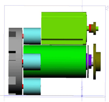
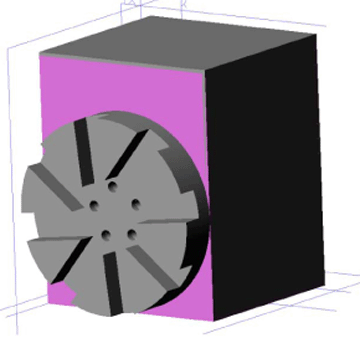
    Here are a couple of the screen shots for the ATC.


    Since I only have a lathe, I needed to design a ATC that only had lathe cut parts. This was as close as I could get. The frame is welded 1/8” steel but everything else is lathe cut. The rotating assembly has angular contact bearings to keep it centered and straight. The motor is a NEMA 34 1200 oz motor. I’m going to use a chain drive to connect the motor to the spindle. There are four locks that hold the rotating assembly still while cutting. The turret uses air pressure to release the locks, but spring pressure to lock everything. This should provide for reliable use. I was concerned that if we lost air pressure, we could ruin the part.


  14. #14
    Registered
    Join Date
    Jul 2011
    Location
    United States
    Posts
    36
    Downloads
    0
    Uploads
    0

    Default

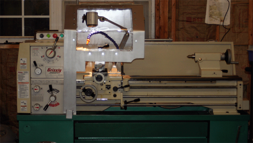
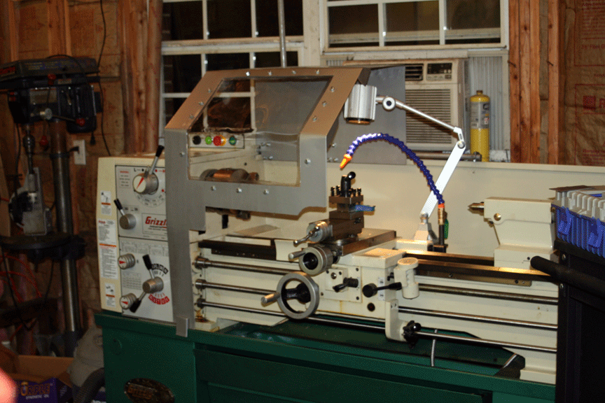
    Since I'm waiting on parts, I figured I would go ahead and make a coolant door.


    nothing fancy, but should do the trick.


  15. #15
    Registered
    Join Date
    Jul 2011
    Location
    United States
    Posts
    36
    Downloads
    0
    Uploads
    0

    Default

    Still waiting on parts. Not 100% sure what is taking so long. I need to give them a call.

    On a side note, I just ended up picking up a G0704. I'm going to do a HOSS conversion on it. The mill just showed up and I will be picking up most of the material to do the conversion next thursday.


Tags for this Thread

Posting Permissions

  • You may not post new threads
  • You may not post replies
  • You may not post attachments
  • You may not edit your posts
  •  


About CNCzone.com

    We are the largest and most active discussion forum for manufacturing industry. The site is 100% free to join and use, so join today!

Follow us on


Our Brands

Wiring help!

Wiring help!