
 Reply with Quote
That is fantastic!
Very nicely mace, simple and even quiet in operation!
I'm really looking forward to seeing the rest of your conversion


I started the CNC conversion of my new Milling Machine in a rather random place, with a pneumatic drawbar. This was rather prompted by this thread:
http://www.cnczone.com/forums/showpo...37&postcount=1
In fact I started off posting in that thread (http://www.cnczone.com/forums/showpo...&postcount=124), but have now decided that I should start a new one, as I am not actually making a spindle, just the drawbar. The intention is a full CNC conversion running EMC2. (I have already done one machine, which is working as well as can be expected for the starting machine).
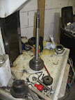
The drawbar fits in place of the standard drawbar with no modifications to the spindle. It uses a finger-style gripper:
From Gibbs
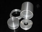
which is released by a specially-made pneumatic cylinder:
From Gibbs
and is held clamped tight by a stack of Belleville washers in the conventional way.
[nomedia="http://www.youtube.com/watch?v=pxrzJ_KfcQ0"]YouTube- Drawbar[/nomedia] shows the drawbar in action.
Similar Threads:
That is fantastic!
Very nicely mace, simple and even quiet in operation!
I'm really looking forward to seeing the rest of your conversion
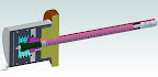
Sectional view of the solid model:
From Gibbs
Andy - is there any way you could show in that cut away view which parts rotate with the spindle and which are stationary. Some hatch lines or ??? Also is there any sort of bearing between rotating parts or just an air gap?
Looks great!
I can describe it in words, if that helps?
The orange/brown part is the top of the milling head, comprising the bearing cap and the top of the rotating spindle. I didn't bother modelling it as separate parts as it didn't matter to me.
The red/pink parts and the dark green part all rotate with the spindle. As do the collet segments and the actuating rod.
The grey parts and the spring are stationary. There are no bearings, just an air gap of at least a couple of mm. It is intended that the spindle should always be stationary when the drawbar is released.
When air pressure is applied the piston moves down until a hardened steel plug (not shown) presses on the top of the drawbar central rod. Then the whole cylinder assembly floats upwards until the lower plate contacts the underside of the collar on the top of the drawbar, and then the drawbar is "squeezed" open.
I have seen many bits of advice that the spindle bearings are "not designed" to take axial loads so decided to use this "pinching" action.
As it happens, I am totally unconvinced about that "fact": The taper rollers in my spindle are rated for something like 50kN static axial load according to the manufacturers.
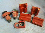
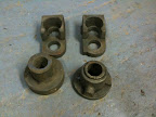
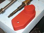
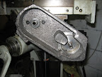
I found that steel (or Alu) blanks of sufficient size for the Z-drive conversion were quite expensive, so I decided to go for iron castings like the original machine builder did.
I made the patterns by gluing together 18mm MDF into blocks, then machining, hand-carving, filling, sanding etc. Then a couple of coats of spray-filler and red-oxide paint.
I then sent the patterns off to a foundry in Birmingham and the castings came back a week later, for £25 each.
From Gibbs
From Gibbs
Wow, your lucky.
I have not been able to find a decent foundry that will do small lots in iron.

andy: great work. We have looked at getting local castings and they don't seem too expensive.
what is your plan for cnc'ing the axis?
sam
I am keeping the Acme screw (I think a ballscrew would need a brake, and I am sure the weight of the knee is more than any conceivable upwards cutting force).Originally Posted by samco

Currently the machine has a rotating screw and a static nut on top of of the machine base.
I am converting to a rotating nut in the same location, with the motor in the machine base rotating the screw through a drive tube coaxial with the screw. I will then fit a locking pin to the existing manual feed (and possibly one to the CNC axis too, to retain the possibility of manual drilling)
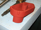
The casting that there are two of is a motor mount, it clamps round an extended bearing housing that pokes into the machine base. The motor fits into the part-circle on the top of the casting.
After a few months distracted with writing drivers for brushless servos in EMC2 I got back into the workshop today.
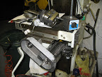
I have finished the machining of the castings, and the Z axis is assembled.
From Gibbs
The design might require a little explanation.
The original design for the table up/down is a rotating leadscrew and a fixed nut mounted in a casting on the base of the machine. The screw passes through into the machine base. I wanted to retain the option of hand-operating the table for those quick jobs you sometimes have, so my plan is to simply lock the screw in the table when in CNC mode, and to lock the CNC axis in manual mode (which is what the boss in the leftmost casting is for) I have therefore replaced the nut housing casting with one which has space for a double angular contact bearing in which the nut can rotate. The housing is extended downwards (to the right in the picture) through into the space in the machine base. The motor mount clamps onto this housing extension. Down through the middle is a machined tube, the upper end of which houses the leadscrew nut, and the lower end of which has the pulley fastened on to it. The pulley allows enough offset of the motor from the axis for the leadscrew to pass past it.
I suppose I ought to paint it.
can you see much of an issue with balancing the spindle bits your making?
We were looking at making a spindle but the grinding and balancing to finish the parts seemed to put it in the too hard basket.
www.vapourforge.com
The max speed of that spindle is about 2000rpm, and none of the actual rotating parts I have made is more than 25mm dia. or so. Time will tell, but I hadn't even considered it, I just saw my new bits as a modification to the existing drawbar.
I spose if its just the drawbar its not so bad, I was thinking of a full spindle.
www.vapourforge.com
It turned out that the leadscrew had too much friction for the motors with the weight of the table on there, so I converted to ballscrew:
From Gibbs
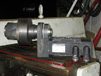
I am rather pleased with how the ballscrew-end machining came out:
From Gibbs
Installed in the machine it looks like this:
From Gibbs
With the motor and drive underneath (this is a rotating-nut arrangement)
From Gibbs
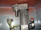
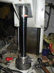
Having spent so much on the other parts, it seemed daft to not protect them, and as the original bellows was worn out, split, and the wrong shape, I spent £50 on a spring cover:
From Gibbs
Your pics are not coming through for me. BTW your work looks great. Be interesting tosee this machine working.
Jess
Well after posting the pics started showing.
Jess
With the Z finished, time to start on Y.
Actually, Z isn't finished, I need to find a way to lock the Z at the top (I decided to retain manual Z for quick drilling jobs), but that is a job for another day.
The ballscrew conversion of the Y axis was a bit of a challenge. The Acme leadscrew was originally screwed into the nut after the table was fitted. Not really an option with a ballscrew. However, due to assembly order constraints the screw has to be fitted with the knee mounted on the machine, so the ballscrew has to go in from the top, and can only be fractionally longer than the slot it lives in.
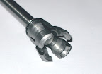
I needed a way to connect an extension to the ballscrew with good concentricity, no backlash and access only from one end, with very little radial clearance.
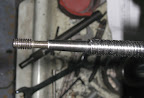
So, I stole an idea from the way that Wohlhaupter attach the shanks to their boring heads. A hex socket grubscrew/setscrew with two sections of different diameter and different thread pitch (actually, the diameters could be the same). You screw it all the way in, screw down the mating part, then back out the screw. The screw screws into the coarse threaded part faster than out of the fine-threaded part, and pulls them ever so tightly together.
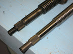
I machined a 6 degree taper on the end of the end of the ballscrew (assuming that Stephen Morse had done his homework) and made a dual-threaded screw.
From Gibbs
Then it is a case of screwing the screw fully home, then screwing on the extension piece not-quite home (so that the screw pushes it off to release it in the future). Then the screw is backed out with an allen-key down the central bore, and it all snugs up tight, concentric and backlash-free.
From Gibbs
How likely am I to remember a few years down the line that that is how it works? Not very, I think, so perhaps a note taped to the inside of the cover is required.
The last castings went well, but preparing the patterns in MDF was painful, it was too porous and hairy. So, I CNC routed the next pattern from a stack of glued plywood:
From Gibbs
From Gibbs
Part-machined and test-fitted it looks like this:
From Gibbs
I was experimenting with knifing putty at that point, the surface finish of this casting was unimpressive, but for £30 it is hard to complain too loudly.
From Gibbs
Last edited by andypugh; 08-12-2011 at 05:26 AM.
andypugh
How did your conversion progress?
I purchased a Harrison mill with vertical head earlier this year and still looking for a manual. The machine is doing well.
___________
Danie
The conversion is going slowly. I keep getting distracted by other vaguely-related things (like software drivers for IO cards)
[QUOT]I purchased a Harrison mill with vertical head earlier this year and still looking for a manual.[/QUOTE]I bought a manual from eBay, it wasn't terribly expensive. Harrison Horizontal Milling Machine Manual | eBay
Thanks,
I will seek for the manual.
_________
Danie