Reply with Quote
Let's review normal operation of the G0602 motor power circuit, and then wire up our new control relay:
The 110V line voltage comes directly from the power cord to the KM relay coil. From there, it travels through the Estop switch, (SB2) and then to momentary push-button switch SB1. Pushing SB1 closes relay KM and enables the holding circuit to keep it closed.
At this point, Power is supplied to motor-direction switch SA, but the motor will not run unless a direction is selected. The relay will remain closed until either Estop switch is turned off, or power cord disconnected. (Or until the Master Switch on my FC stand is turned off.)
At some future time, I may want to control motor-direction by Mach3. Right now though, I only want Mach3 to start and stop the motor by G Code command. I will manually select motor direction at beginning of program, and turn motor on and off by turning motor contactor KM on and off.
When the motor control relay is OFF, the motor will be controlled manually as normal, through the relay NC contact.
CAUTION!! THESE ARE 110V AC WIRES. MAKE SURE POWER IS OFF AND MACHINE UNPLUGGED!
CAUTION!! THESE ARE 110V AC WIRES. MAKE SURE POWER IS OFF AND MACHINE UNPLUGGED!
CAUTION!! THESE ARE 110V AC WIRES. MAKE SURE POWER IS OFF AND MACHINE UNPLUGGED!
We will wire this up by first cutting the wire (#4) between Estop switch SB2 and Push-to-start switch SB1:
The Estop end is wired to relay Common terminal, using a crimp spade terminal and a crimp splice:
The Push-button end of the wire is routed to the NC terminal of relay:
Normal manual control of the motor is now restored.
The way things are wired, all we have to do to activate relay KM, is provide a connection from Estop to Neutral wire of power cord. That connection is available on contactor KM, but it is difficult to reach. I opted to remove 4 screws from the electrical box and slide the box back to achieve access.
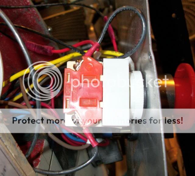
The easier way is to just remove the relay from its mount. See the big hole that I drilled for thread-sensor wires? Just to the left of it is a screw and washer:
The KM relay is mounted on a slide track. That little screw and washer is the only thing keeping the relay on the track. Removing the screw and sliding the relay to the right takes the relay from its mount and allows access to all KM terminals. Whichever way you access it, now is the time to make sure ALL terminals are tight and all wire crimps good.
WHOOPS! I would have drilled that big hole in a different place, had I known then how the KM relay is removed. The hole and sensor wires will be relocated to the upper right hand corner--for both easy relay-removal and to route the thread sensor wires well-away from the rotating spindle.
Here is the Mach3 control wire connected to the control-relay NO terminal and routed back to the KM electrical box with the other wires:
This is the N terminal where contact will be made using a slide terminal:
The relay coil will be powered by 24V and a G540 output:
Mach3 activation of motor-control relay also BREAKS the connection of the push-button start switch and deactivates the holding circuit. Motor control by the new relay is absolute and G Code On-Off spindle-motor control is assured.
The Original Estop switch motor-stop function is retained for both manual and Mach3 operation. Later, we'll also wire the G540 Estop function to the same switch, using the second set of NC contacts.
CR