Reply with Quote
Some more oldham coupling -- with rollers.
http://www.spinea.sk/page.php?id=1


Here is some math and CNC info about gear profile... In short, it can't be described by two arcs
http://gears.ru/transmis/zaprogramata/2.139.pdf
Some more oldham coupling -- with rollers.
http://www.spinea.sk/page.php?id=1
Ah, cool! I have to write a rhinoscript or something
Hey Zoid, I like that last reducer. Only comment is the (radial force) balls need separate setscrews, or better still, no thread in the main shaft, and a nifty way for one ball to push against the other, so radial load equalizes.
BTW, I've got a bucket of Santotrac grease when you get down to it. It was a minimum order thing. The stuff is like ear wax, if you've never seen it. ha
Mike Visit my projects blog at: http://mikeeverman.com/
http://www.bell-evermannews.com/ http://www.bell-everman.com
Any chance I could cadge a sachet of that from you Mike?BTW, I've got a bucket of Santotrac grease when you get down to it. It was a minimum order thing. The stuff is like ear wax, if you've never seen it. ha(when I finalise my Z axis design)
Bill
I'd be happy to send you some, Bill! I'd be tempted to deliver it by hand in two weeks, but you're a bit far to the west of where I'm going. Not sure how shipping of unidentified gel-like stuff is going to go...
I could be holding down a pub stool in London on Saturday night the 18th, if you want to pick it up and tip an ale.
Mike Visit my projects blog at: http://mikeeverman.com/
http://www.bell-evermannews.com/ http://www.bell-everman.com
Sounds good!Originally Posted by Mike Everman

What about this for preload? You would use belleville washers stacked under the piston!
Zoidberg-
If you were to add a small drilled hole thru the shaft and thru the plunger, you could preload the springs, install a pin in the drilled hole then slide the shaft in place. Once in place, pull the pin and release the spring tension. The same procedure as changing brushes in an alternator.
Edit- You may be able to use this same pin process to cut the rounded shape on the end of the plunger in a lathe. Perhaps a larger pin to load it into the bearing (smaller OD) and a smaller pin to turn the OD of the plunger (Bearing bore ID).
Keith
Hi, the graphics look great, I have a more down to earth question: how do you plan to machine these when you finally settle on a design and how much do you think you will spend if you contract the machining?
Im learning how to make gears as a hobby and this thread have a lot of info, but it missed what Im asking
Pablo
I have a mill, i had it running on steppers but with bad performance so i sold them and is going to use servos in closed loop with EMC instead.
To make gears later, i will try real hobbing and gear shaping (for internal gears), but for that i need an servo spidle and a rotary table! So i will build a traction drive at first which should be doable on a mill!
Zoid,
The metallic traction drives you are designing, and quite well, are not easy to make, and I can't imagine how you could do it with anything but an OD grinder or a really, really good tooling lathe. I have been there, and tried with all the right tools, and found that it was far too easy to be tearing hair out to find that a .0002" runout or out-of roundness for any one element. It is tempting to put springs in for preloading to compensate, and that will work to a degree, but I've found it always creeps up as a drive-line flexibility or limits the torque no matter how it's done.
I'm not dissuading you, rather sharing experience from when I also thought it was easy. It may be that you come up with something that makes it easy, and I do hope so!
I have been a student of traction drives for many years, and the machine tool/automotive grades have a few things in common:
Hardened and ground high alloy rolling elements
Extreme contact pressure
Great attention to a high shear component traction fluid or grease
Great attention to differential thermal expansion
My focus was mostly on very high accuracy systems, so at the DIY level, I do believe you will make something that works, and if this is the way you want to do it, then you will have fun. If you just want to get it done so you can use it, it is very easy to make a worm gear set with your mill.
Mike Visit my projects blog at: http://mikeeverman.com/
http://www.bell-evermannews.com/ http://www.bell-everman.com
Not to disparage the "do-it-yourself" approach by any means... but if you just want a zero baclkash table without a science project, you might want to look for a surplus cyclo-reducer or harmonic drive. Like this $40 one (about 8" in diameter, 4" thick):
http://www.hgrindustrialsurplus.com/...?id=12-176-336
I bought a similar one a while back - haven't done anything with it yet, but I dug up the specs on the internet. Zero backlash, 59:1 ratio, heavily preloaded crossed roller bearings that can withstand fairly heavy radial, axial, and moment loads.
I think they were originally used as joints for robot arms.
Those are great! $40 gets you an incredible rotary table.
Mike Visit my projects blog at: http://mikeeverman.com/
http://www.bell-evermannews.com/ http://www.bell-everman.com
Thats a nice reducer! But i am in this for the joy of experimenting and designing stuff
I actually havent decided which way to go!
http://gearnew.narod.ru/fangear.html
there is a russian patent, which might be easier to implement -- it uses ordinary gear teeth and don't need coupler.
Axes of input and output shafts are offset by E, three gears with the same offset E are mounted with the bearing on eccentrics (alse E offset) 120 deg apart. reduction is R/E, where R is centroid radius of outer gear.
If i just could make the gears
this kind of gears is used in automatic gear boxes in cars -- it might be possible to reuse them...
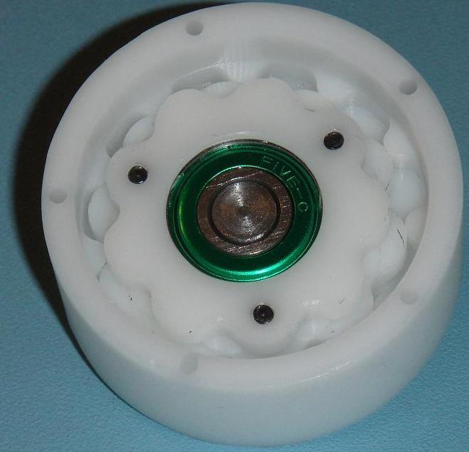
Inspired by this thread and the .pdf found by aystarik, I built a dual stage 90:1 cycloidal reducer. The main issue in creating the reducer is the generation of the cam profile as it is a fairly complex function. To solve this problem I wrote a Python script to automatically generate a .dxf file with the specified parameters.
Autocad drawing of the reducer:
A shot of the inside of the reducer showing the 9 lobe cam on top, the 10 lobe cam on bottom meshing with the 11 outer pins in the housing:
The reducer was machined from 2" diameter Delrin rod I had lying around.
Video of the reducer in operation. The drill is running at around 2000rpm and I can only hear the noise from the drill.
"http://www.youtube.com/watch?v=Ye8NtIZkixI"]YouTube - Hypocycloid reducer
If you would like the script I used to generate the cams and some more pictures, see my page on the subject
I plan to make an new version with two bearings on the input shaft as the single bearing allows some play. I also need to measure the backlash.
Very cool
I made a rhinoscript based on your code
Code:Option Explicit Sub Hypocycloid() Dim p, b, d, e, n b = Rhino.GetReal ("Pin circle diameter") d = Rhino.GetReal ("Pin diameter") e = Rhino.GetReal ("Eccentricity") n = Rhino.GetInteger ("Number of teeth") p = (b/2)/n Dim i, arrPoint, arrPoints(360) For i = 0 To 360 arrPoint = Array(CalcX(p,d,e,n,Rhino.ToRadians(i)), CalcY(p,d,e,n,Rhino.ToRadians(i)), 0) arrPoints(i) = arrPoint Next Rhino.AddInterpCurve(arrPoints) Dim xtemp, ytemp For i = 0 To n+1 xtemp = p*n*Cos(2*Rhino.pi/(n+1)*i) ytemp = p*n*Sin(2*Rhino.pi/(n+1)*i) arrPoint = Array(xtemp+e, ytemp, 0) Rhino.AddPoint(arrPoint) Next End Sub Private Function CalcYP(a, e, n, p) CalcYP = Rhino.ATan2(Sin(n*a)/(Cos(n*a)+(n*p)/(e*(n+1))), 1.0) End Function Private Function CalcX(p,d,e,n,a) CalcX = (n*p)*Cos(a)+e*Cos((n+1)*a)-d/2*Cos(CalcYP(a,e,n,p)+a) End Function Private Function CalcY(p,d,e,n,a) CalcY = (n*p)*Sin(a)+e*Sin((n+1)*a)-d/2*Sin(CalcYP(a,e,n,p)+a) End Function
 Posting Permissions