
- Adding stepper power to the chuck.
-
Registered

-
-
Registered
 Re: Adding stepper power to the chuck.
Machineable wax… and homemade. I figured it was cheaper than buying plastic stock, I could reuse it, and it would be a useful material to have. Again, I took my inspiration from CNC Zone.
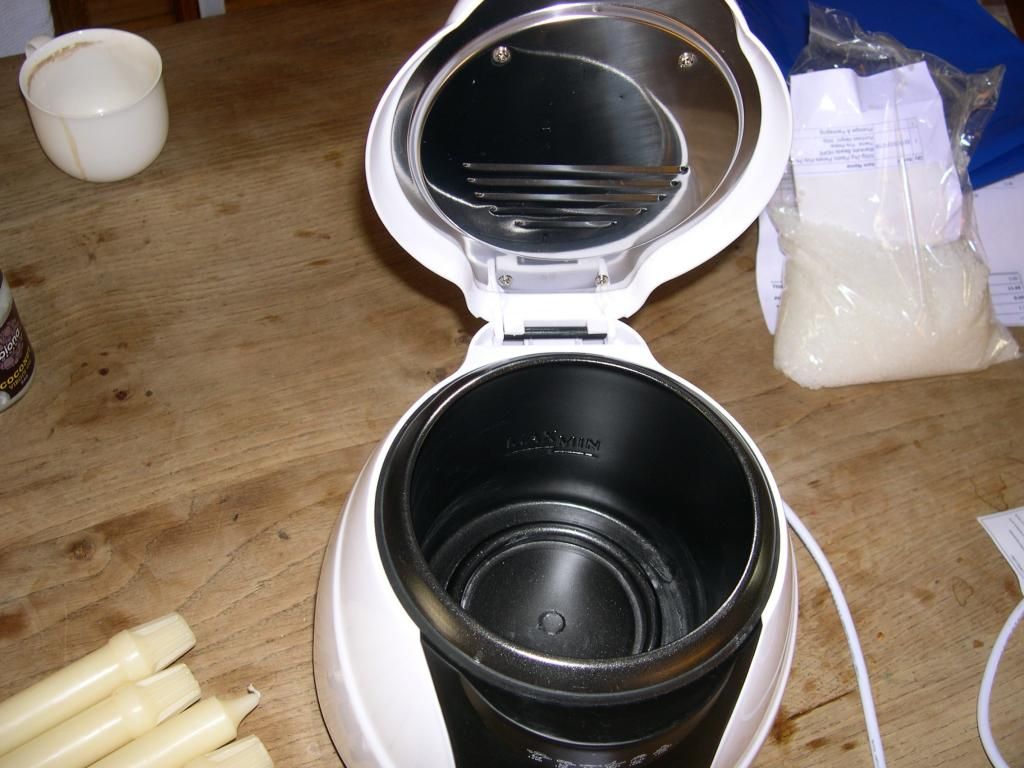
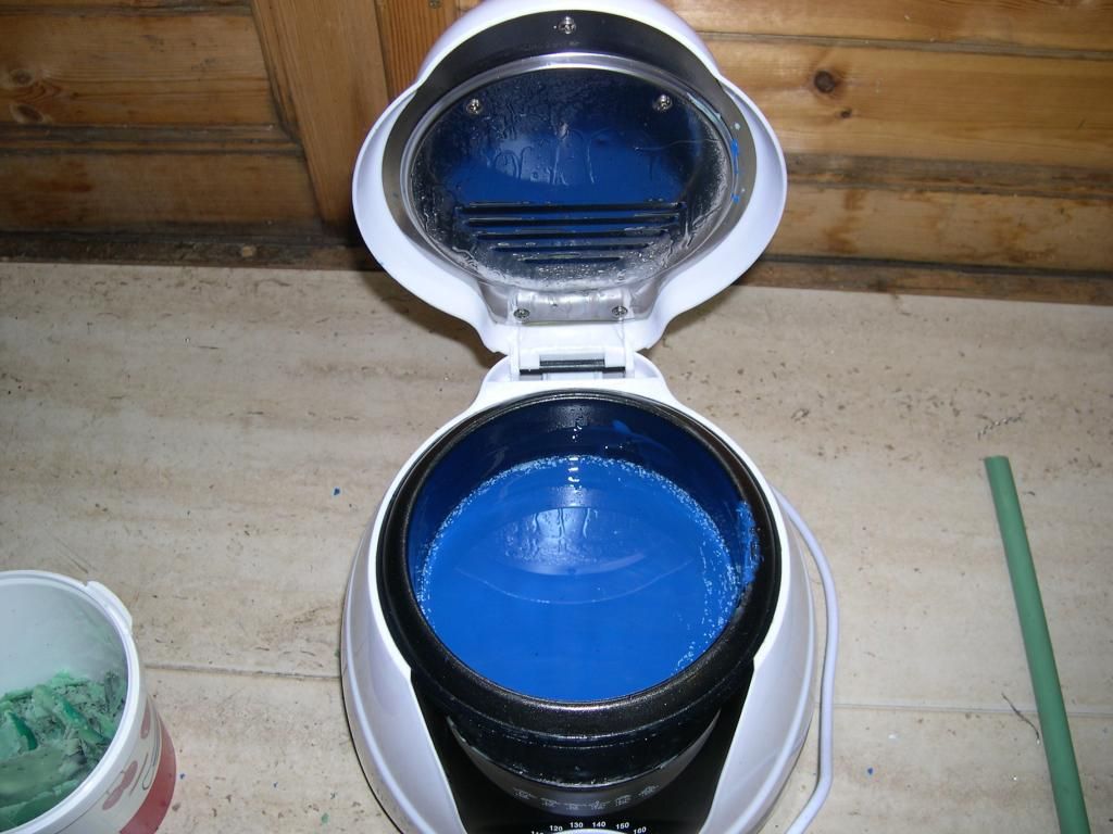
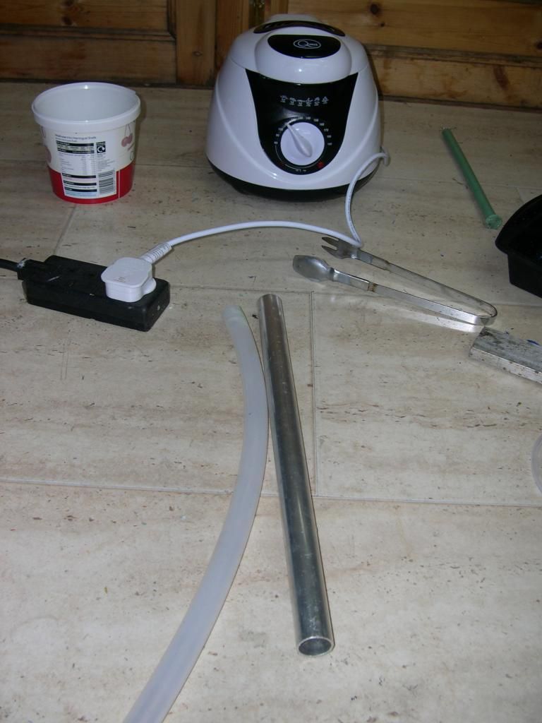
So I found some candles. Ebay got me a cheap deep fat fryer with a temp gauge, some blue plastic postal bags (LDPE), some plastic pellets (HDPE- used for stuffing toys), some wax crayons for colour, a length of silicone tube, and finally a cake tin as a mould.
Melt the candles, remove string.
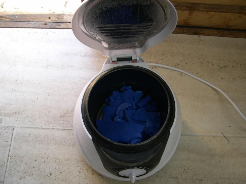
Cut up plastic bags and add in. Turn up the heat to about 120C and wait- stirring occasionally.
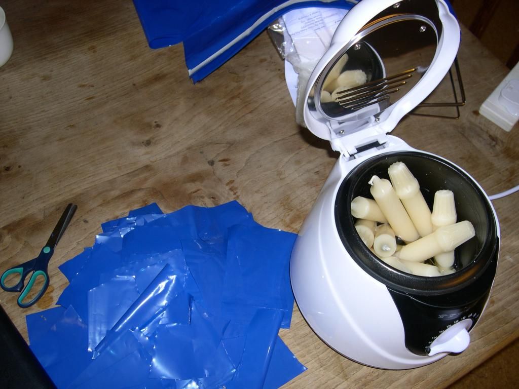
I used 4:1 candles to plastic. Note: my candles are fancy ones so probably have stearin added to them.
The process starts to get smelly when I turned up the heat and added the plastic- so I got sent to the shed.
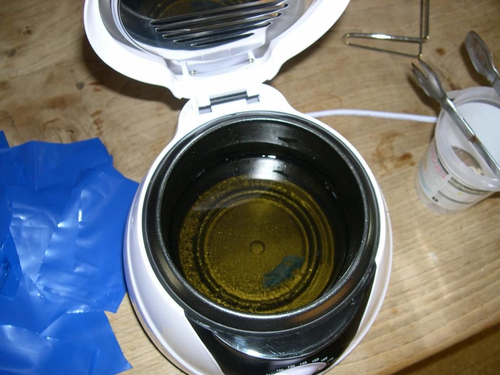
It takes a long time to dissolve the bags, but eventually the mix went smooth enough- just a few lumps.
I made some pretty lame attempts to decant the wax into the moulds- went OK but left me scratching my head.
The problem is that I had become so concerned with not burning myself the whole decanting process became more complicated and actually more dangerous.
Think hard about this and practice with cold water in the fryer so you have a nice slick simple safe process.
I went to fix the roof while I thought about it.

My fryer has a removable lid so it became easier to pour it than to decant.
I mixed up the same mix but instead added the HDPE pellets and a green wax crayon to give some colour. This mix needed 140C to melt it well. The wax made more smell.
Having got two batches of wax, I decided to re-melt them- process them a second time. In both cases the melted wax was smooth on the second melt- although the HDPE mix is thicker and “stringy-er”. The green wax crayon gave a disappointing result. Perhaps proper candle dye would be better.
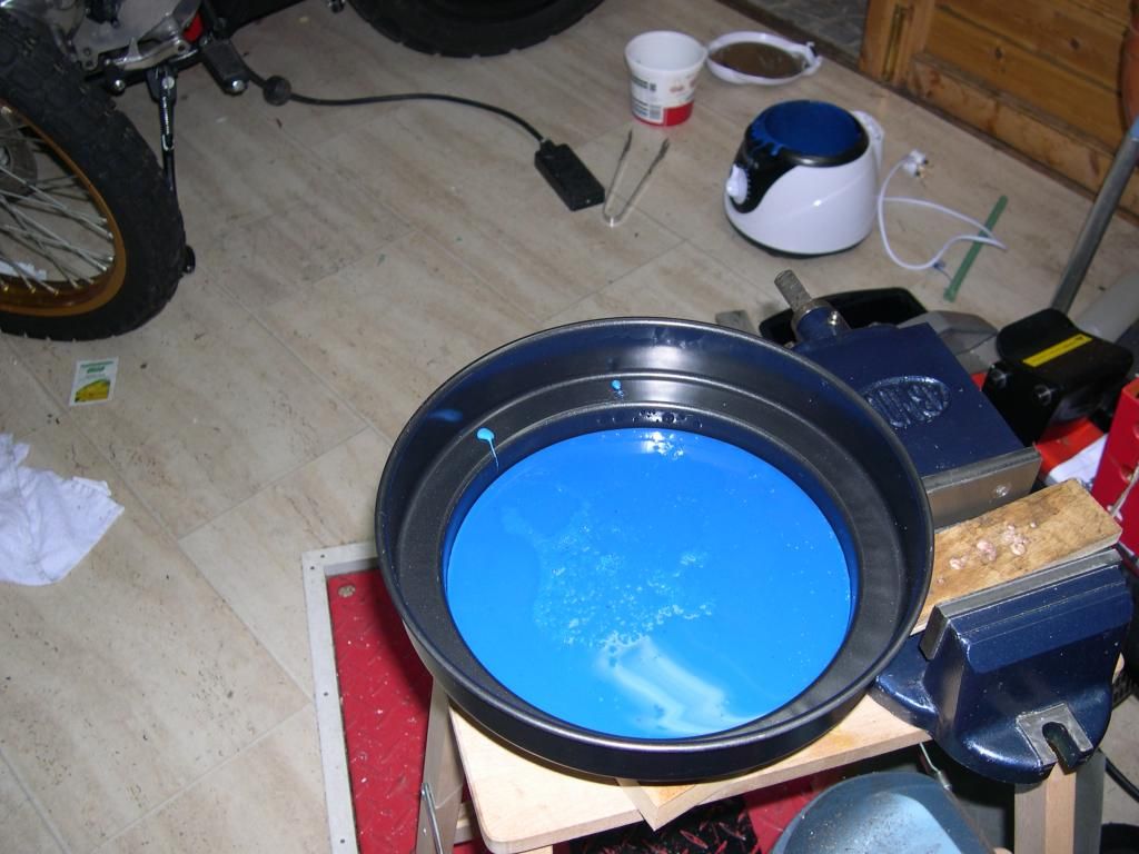
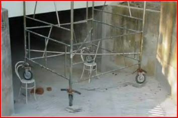
Drop the wax into a mould (cake tin) and a squirt into the silicone tube (held snug inside a metal tube to keep it straight).
Use a good sturdy chair to put your work on.
And I have two wax blanks to machine with.
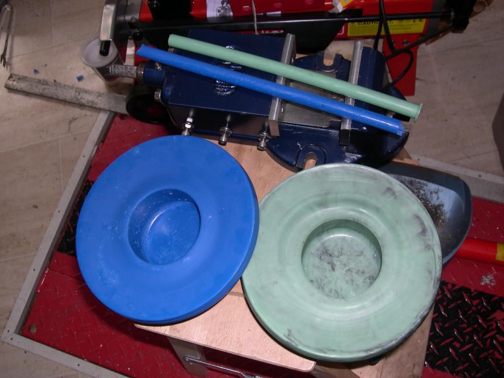
Note: I tried to make the green darker by adding black- but really it just left it streaky. The two rods I made were so that I could compare the machining characteristics and their strength easily.
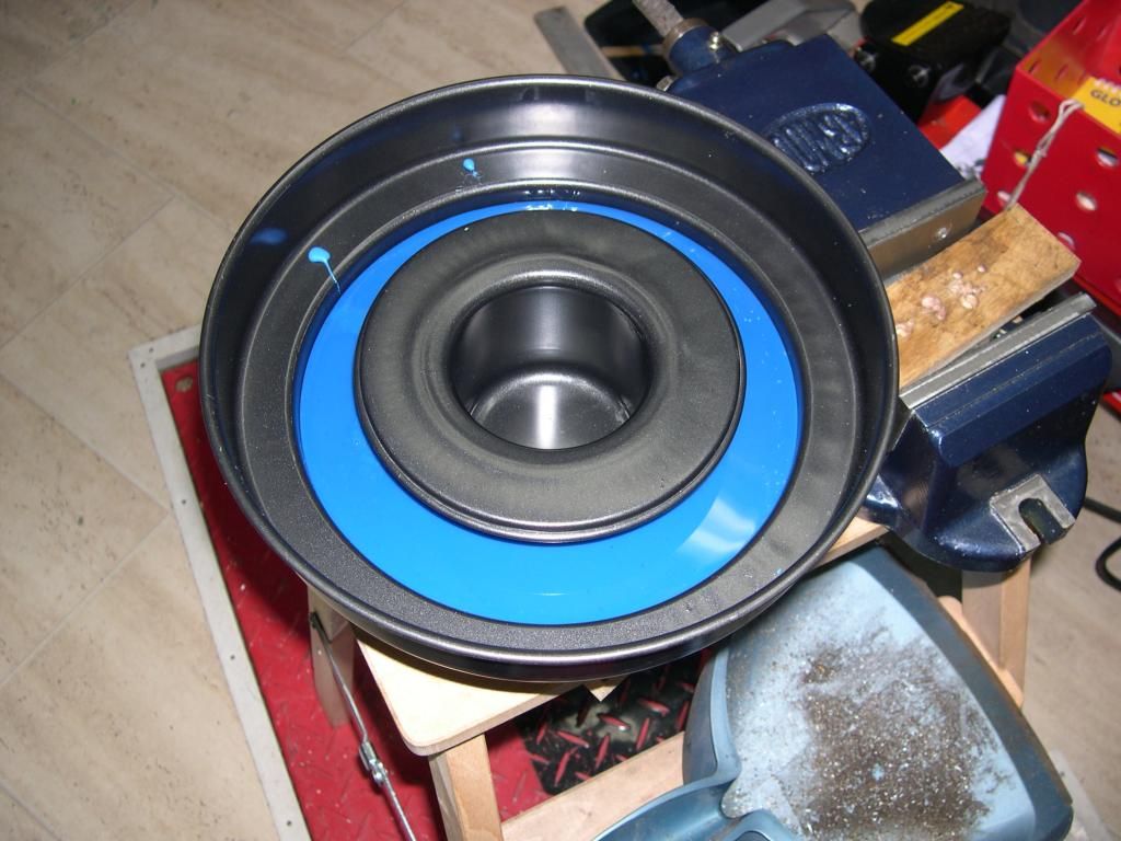
Next stage is to machine the pulley cavity.
-
Registered
Re: Adding stepper power to the chuck.
Julian,
Your work on the pulley is impressive, but I hope those photos of the roof and painting are tongue in cheek, because if not, we may never see the end of this project. Not sure why you need the stepper for threading if you have the VFD drive. Also, you will need some way to quickly release the tooth belt when running the spindle with the regular motor.
-
Registered
Re: Adding stepper power to the chuck.
"I hope those photos of the roof and painting are tongue in cheek, because if not, we may never see the end of this project." Ha!
Not sure why you need the stepper for threading if you have the VFD drive. I want to do rigid tapping- or specifically large "rigid thread cutting" and the VFD is not suitable for that.
Also, you will need some way to quickly release the tooth belt when running the spindle with the regular motor. Yes, good point. This is going to be a tool I put on the machine when I want its functionality- not a permanent fixture.
I have another project up my sleeve to replace the stepper on the bridge lift with a simple car window motor.
I'm deep in upgrading the machine at the moment, lots of projects that add functionality and improve quality. The problem is that you have to line these projects up so that they fit in order- each one allowing subsequent ones to be completed.
Any idea about stopping the quill drive from rattling? When I run the mill to plunge holes then the constant torque on it makes it run real quiet- but when I am milling with intermittent loads the keyed pulley drive on the top of the quill rattles on the splined shaft.
It's no great problem- I just wondered if there was a quick fix?
I quite fancy casting a concrete bench for the machine later this fall.
Gosh, concrete turns out to be complicated stuff!
I'm still stuck in the research for that.
The next big project is to upgrade the Z axis to give it much more precision.
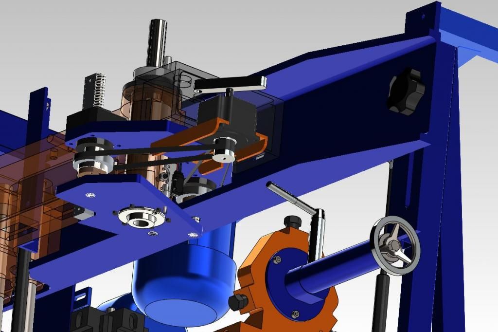
This is a really unclear view of the model- but perhaps you can make out I'm adding a further lead screw at 180 degrees to the first (which I've moved).
-
Member
Re: Adding stepper power to the chuck.
That's quite a project. Contact JT at Shopmaster, he has a file on how to quickly fix a loose or worn spline.
-
Registered
-
Registered
Re: Adding stepper power to the chuck.
Julian,
I hope you drilled some holes in the steel hub to give the epoxy an anchor, so it can't slip on the hub. I always like to see a guy who can figure things out- back 20 years ago when I bought my first Shoptask, a lot of guys in the hot rod community told me I was wasting my time and needed a Bridgeport and a big lathe. I did a tremendous amount of work on that machine, including surfacing chevy heads and valve seat work. Later on a lot of those guys would show up at my garage with some project in hand. If you look in JT's brochure on his website you will see some of my pictures.
-
Registered
Re: Adding stepper power to the chuck.
Ah, you know- I didn't drill it.
It would just be a re-cast of the pulley if it did slip- although I'm sure that would be a pain as it would happen just when I didn't want it to.
I've long since made my peace with this machine- and still consider it good value.
As I've improved it, things have gotten better and better.
And as for alternatives- I just don't have the space. So there area actually very few real alternatives for me.
I love being able to do other jobs while this machine is busy.
-
Member
Re: Adding stepper power to the chuck.
Very nice work. Would you consider sharing your Solidworks model of your bridgemill?
Smallblock: Did you surface the Chevy heads by doing half and then moving the head to reach the second half?
Last edited by jlmccuan; 08-24-2014 at 01:15 PM.
-
Registered
Re: Adding stepper power to the chuck.
Jl, I'm not sure about sharing the SW files.
I think it would either be a service to owners or a disservice to JT- I feel torn.
Any general feelings here?
-
Member
Re: Adding stepper power to the chuck.
Julian,
Your solid works files look to be modifications to your machine. I can't imagine any reason why Shopmaster would care what you do or if you give your plans away. Send them an e-mail if you are uncertain.
-
Member
Re: Adding stepper power to the chuck.
Julian,
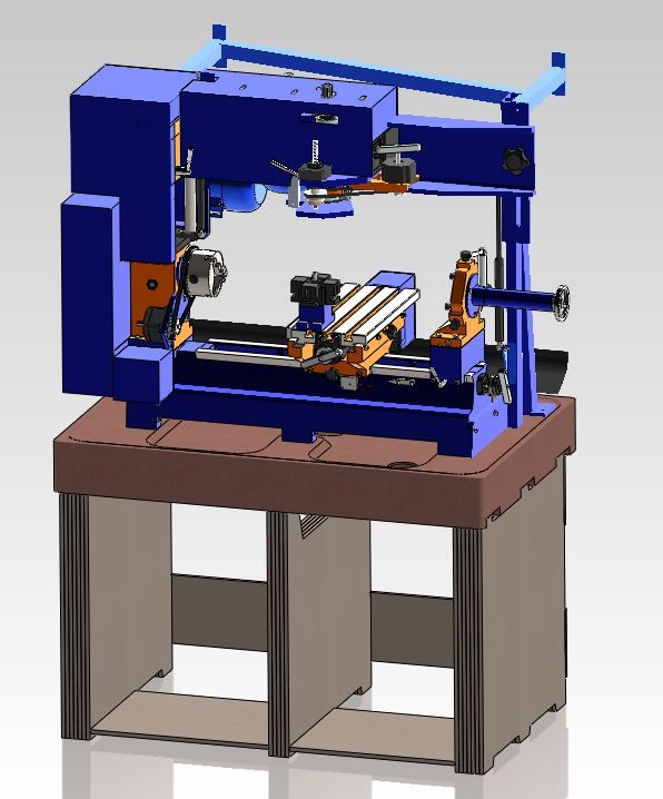
Just a friendly criticism of your design- Obviously you want to add the big channel piece to reduce any flex in the flat plate that comes with the machine. Unfortunately by mounting it as shown, you are required to mill away all the webs to clear the lift posts, effectively negating any added strength because at the point of radius you have the same flat plate as the standard machine. Your enhanced vertical and what appears to be a wall mount strut will work to reduce flex. You could gain the desired stiffness with much less effort by simply bolting a piece of 2" X 1" channel iron along the entire length of the standard plate, flush with the top edge with the channel webs facing to the rear of the machine. It will clear your standard lathe motor mount, and for the mill motor you will only need to mill a couple matching slots in the channel, space the motor back by 1" and use a longer belt. As for your dual ball screw design, I have seen that done successfully on machines going back to the 90's, so no worry about the results there.
-
Registered
Re: Adding stepper power to the chuck.
You make a good observation I37, thank you.
I did explore several alternative arrangements, I don’t think any of them were perfect,
neither is my final arrangement- it was simply my chosen compromise.
The C beam was chosen because my primary concern was whip and chatter.
I imagined that if I had a “super rigid” beam, flex would not be reduced much because
the “quadra-lift” assembly is not very resistant to torsional loads.
My goals in modifying the bridge was to both increase stiffness and add to the mass of the bridge.
The C beam is thicker and obviously heavier. Originally I was going to add angles to the top and bottom
of the standard plate (just as you suggested) – it is a good solution to the very obvious flex of the plate, but I feared
that it would not increase the plate mass as much as I wanted, and the bolts – even when set say 6 inches apart- would
not have constrained the flex nor the higher frequency chatter as well as a C section might.
Lastly, when I found out how little the C section cost I was persuaded to use it. I’m a bit of a cheap skate like that.
The C section had a surprisingly impressive impact upon tool chatter- it really seems to have helped in this regard-
although an improvement in one area just shows up problems in another!
Thanks for the words of encouragement about adding an extra ball screw to the Z axis, I really want to improve its accuracy.
At present, the arm to which the ball screw is attached bends ever so slightly when the Z axis reverses, it takes quite a large Z movement before the tool moves.
In addition there is some play in the quill, and having the ballscrew apply its force so far away from the quill axis it definitely yanks the bottom of the quill
either towards or away from it- and that movement shows up at the tool tip.
I added 4 little pinch bolts to the sides of the quill casting to help remove the play, but it is difficult to counter all the forces on the quill- not least of all the belt tension at its far other end.
I think the Z axis mods will be an improvement- thanks again for the encouragement I37.
-
Member
Re: Adding stepper power to the chuck.
Your mods are very interesting and one of the reasons I wanted a copy of the solid model. I have some changes I'll need to make for a couple of my projects as well. Do you have the movements of the axes and bridge head integrated into you model?
Your method of making the drive gear is interesting and I think turned out well. I think you'll be OK as regards keying the epoxy into the metal. That's a lot of surface area with the grooves in place. And, as you pointed out, easy to retrofit if needed. What oz. size stepper did you use to drive it and what is the drive ratio?
One of the things I want to do is surface cylinder heads. The machine has the movement needed but not the clearance from the mill spindle to the bridge column. I assume that is the 22" X travel since the lathe compound would need as much travel as possible in it's Z axis. The heads are 20" so there's no way to reach the X+ end of the head with the mill spindle without turning it around. Any thoughts on accomplishing that? Is it possible to increase the Y travel and maintain any rigidity at all? Or should I build a Y slide fixture and move the head off the table + and - Y. The final option I've come up with is to machine half the head, unmount it, spin it around and finish the second half. That is my least favorite option and funny things happen when you remove a workpiece and remount it. I suppose I could use my rotary table, but most of the work would be unsupported that way. I hope you guys have some good input on that.
I'll be picking my machine up this week. It is a Patriot VFD CNC. It was bought new in 2013 and never set up. Hopefully all the bits and pieces were shipped as I doubt Shopmaster will work with me on that. After all, who is to say it wasn't lost during the time it was stored? I sent JT an email asking if they transferred warranties, but haven't gotten a response. Any ideas which side he'll come down on? The original owner says he will work with me to get any problems resolved through him as the registered owner if we have to, but I'd rather be up front with JT about the whole thing. Has anyone else seen this situation? Of course, now that I've brought it up here, perhaps JT will put the pieces together and void the warranty altogether. We'll see.
My past CNC equipment experience has been mostly Amada and Fanuc based machines using their proprietary software. I have done a few PC based control retrofits, though, in hi-def plasma, turret punches, a small mill, and a robotic welding cell with 3 slide tables loaded and unloaded by a larger material handling robot feeding work to a welding robot for a lights out cell. Some of that I used Mach3 for the motion control. We also wrote our own offline programming package for a plasma, some OTC robotic welders, and a cell with one material handling robot loading a press brake, ironworker, and a VMC. Those were fun projects, but I don't think I could repeat the 100 hour workweeks now. I had a great Chinese programmer nobody else could understand, so they left us alone and uninterrupted for weeks at a time. All that said, I'm looking forward to being creative with a smaller, flexible machine for my projects, which will be mostly aluminum.
Sorry to ramble on and hijack your thread. Again, I like what you've done and will steal some of your ideas for my machine I'm sure. Please post more pics and details.
-
Registered
Re: Adding stepper power to the chuck.
Hmm, such a large skimming operation will require some consideration- I’m not sure if the simple extent of the travel is the only concern.
Sounds like if you clamped that head down real well it would twist the table.
Then you have the question of the flatness of the bed and the design of the bench.
I don’t think the flatness you are trying to achieve will be possible with the standard bench- just moving the weight of the head 20” will change the bow in that bench and move more than your tolerance.
Finally, when you look at the ways of the table- they are not that long or wide, so you won’t need much play and the actual problem you see at the ends of your head may be significant.
But you are right, the biggest problem is that once you got that big old head on the table it will prevent the table moving very far towards the chuck end.
Don’t be put off by me though, my approach is to think of all the problems I can, then test to see what problems I’ve got, then experiment to see that I really understand those problems.
Finally, with all the problems in my head- try to fix them.
My experience is that if you understand the problem well enough, you can overcome it.
Sounds a great project, also sounds like you may also be casting a concrete bench.
-
Member
Re: Adding stepper power to the chuck.
Funny you should mention that. We are building a new house. Concrete floors, walls roof, over a huge steel framework. The roof beams are 24"x12"x36' and the webs are 5/8". 201lbs per linear foot. Over that are 8" channel spaced every 4 feet, with the concrete decking on those. All set on steel columns and the roof at ground level. So my wife says, "I think I want concrete countertops." Most of the bathrooms are cast concrete. So when you mentioned casting your bench in concrete, it got my attention.
-
Registered
Re: Adding stepper power to the chuck.
" One of the things I want to do is surface cylinder heads. "
Jim,
You can build a fixture to hold the head in the long axis of the cross table and surface about 1/2 at a pass, then slide the fixture to do the second half. With careful setup it works fine, but if you plan to be in the business of surfacing heads, you are wasting your time. For that you need to invest in some specialized equipment.
-
Registered
Re: Adding stepper power to the chuck.
How about making a support for the head and mounting it in front of the machine-with the surface to be machined facing the table.
Then mounting an indexable spindle on the table and moving that across the surface of the Head?
Big job, but I have something like this already growing in mind but for my wood router- this would allow me to do some CNC joinery- and big joinery at that.
-
Registered
Re: Adding stepper power to the chuck.
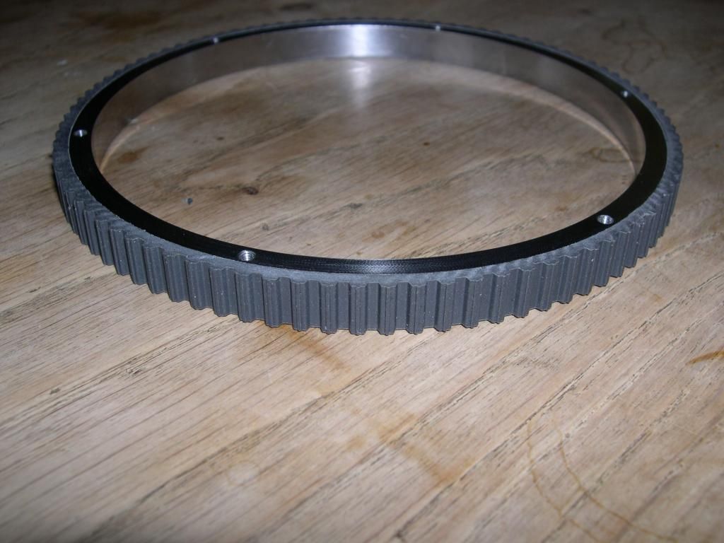
In the picture below hopefully you can see that at the top of each of the "teeth" there is a little ridge that stands higher.
This is due to the fact that the belt has a little groove in the valley between the teeth. I guess this improves flexibility of the belt.
For the pulley this is a problem as not all belts have it, and this little ridge holds a conventional belt off the pulley enough so that it does not engage properly.
The solution is to simply turn the ridges off. Once this was done my new belt engages perfectly.
This was easy as my epoxy is filled with metal not sand- machining is practical and went without a hitch.
-
Registered
Re: Adding stepper power to the chuck.
Sorry jlm, I missed your questions:
What oz. size stepper did you use to drive it and what is the drive ratio?
I'm not sure, I took it from the bridge drive.
I was going to use a 12dc motor on the bridge drive and liberate its stepper motor.
Although, I have been thinking about tramming the bridge, and I realise that it is easier to move the bridge by very small increments when there is a stepper on it- more difficult when I'm flicking a motor switch on and off.
I'm toying with simply moving the stepper when I need to use the chuck drive.
I don't think this chuck drive is going to be used very often, less often than I need to move the bridge, but it'll be useful to have when I need it.
It'll provide a dividing head facility and I will be able to cut large and unconventional threads in the lathe- not to mention some good options if I fit a grinder to the table.
And for the cost of it, I can't complain- some scrap steel, some resin and a belt AND I've got machine-able wax now!
- Adding stepper power to the chuck.
Tags for this Thread
 Posting Permissions
- You may not post new threads
- You may not post replies
- You may not post attachments
- You may not edit your posts
-
Forum Rules


 Reply with Quote


