
- XY stage for dslr film scanner
-
Registered

 XY stage for dslr film scanner
I'm working on building a film scanner using a dslr and a macro lens. The idea is to take many pictures of a negative and then combine them in software. Here's the prototype:
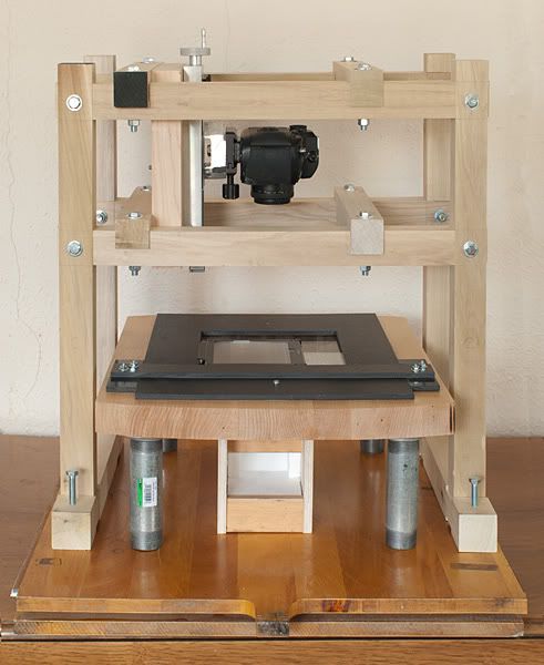
Currently, I manually slide the negative holder from spot to spot to scan the negative at 1:1 with a DX slr. For a 6x7cm negative, it requires 25 frames to cover. The results have been promising, but moving the negative carrier manually gets tedious, especially with bigger sheets of film.
As a result, I'd like to automate the negative holder movement, perhaps using an x-y lead screw stage with stepper motors. This seems similar to what some of you CNC folks are doing, although the load and rate would need to be much less. I'd probably size the stage to enable scanning of 5x7" and smaller negatives. With a lens at 1:1 magnification, the stage would need to move between 5mm and 20mm per sample area, depending on the orientation of the camera sensor. This doesn't have to be supper speedy, as taking a picture every 5 seconds or so would be fine.
Any suggestions as to the best way to do this would be greatly appreciated!
Similar Threads:
-
-
Gold Member

The idea certainly sounds do-able.
In order to drive the stage in the pattern that you want, you will probably want some kind of PIC or Arduino or other microcontroller-based stepper motor control unit, which sends pulses to stepper motor driver boards.
There are circuits used for robotics that could be modified to do the job, or you could look for projects such as "rotary table indexers", which could be modified to do something similar.
How much accuracy do you need in positioning?
Maybe you can integrate shutter control of your DSLR with the stage movements so that all you have to do is push one button.
-
Registered
Thanks for the reply! Right now I'm leaning toward using an Arduino with a stepper controller add-on. Yes, I'd really like the system to automate both negative positioning and camera firing. You can see a commercial Z-axis at: StackShot - Focus Stacking Macro Rail You can see a DIY version at: www.photomacrography.net :: View topic - Automated Focus Stacking Rail.
In my case, obviously, I'm not looking for a Z axis, but an xy axis. Perhaps using two of the linear rails place perpendicular to each other?
Regarding the accuracy, the stitching software will work with from about 25% overlap down to about 1% overlap. The more accurate the process, the less overlap we need, and the less frames we need to cover the negative, but we're flexible, as I realize that one can quickly run into the law of diminishing returns. Would + or - 1mm per exposure be too difficult to achieve?
The sensor on by Nikon D200 is 23.6 × 15.8 mm, and with a lens at 1:1 magnification, that's the same size piece of the negative that'll be covered with one exposure.
-
Gold Member
I think that you should be able to get plus or minus 1 mm without difficulty. If you end up going with a conventional ball screw drive, you will have to play with the numbers as far as screw pitch and microsteps, giving due consideration to the fact that microsteps may not gain any more positional accuracy for you, so you might want to choose your screw pitch with single or half steps in mind.
Linear stages can get expensive - but maybe the relatively small size of the negatives that you are handling will keep the cost within reason.
One possible alternate approach might be to repurpose a part from a regular CNC router design - for example, the Z-axis drive described in the following thread (sorry, it is over 30 pages long, but the info and photos are buried somewhere in that thread) could be doubled up to give you X and Y motion, or you could simply repurpose any CNC router design, leaving off the Z-axis, and simply mounting the camera to the gantry:
http://www.cnczone.com/forums/diy-cn...p_machine.html
But maybe a fixed gantry/moving table design would be better than a moving gantry/fixed table design (just thinking about keeping the camera steady rather than moving it)
-
Registered
Thanks for the link. I will definitely check it out. Keeping everything flat and aligned is a big challenge. Right now, the negative carrier rides on a 1/2" thick 12"x12" glass plate. The plate isn't perfectly flat, but it's pretty good.
-
Registered
Do stepper motors vibrate when powered up but not moving?
-
Gold Member
Possibly, depending on the specifics of the driver.
Oftentimes when a stepper motor is being driven by a "chopping" driver, you can hear the motor "singing", which is a type of vibration. Some drivers reduce the current while the motor is stopped, which may diminish that behavior (and may also reduce power dissipation and heating of the stopped motor).
Also, especially with a microstepping driver where the rotor is stopped at a position other than a natural motor detent, slight differences in the phase drive voltages over time (due to approximations used in calculating the complementary drive signals) would be expected to result in some vibration of the rotor, although it's possible that rotor inertia could damp that out.
I've never actually measured it, but it would seem to be an interesting exercise to hook up an accelerometer to a motor and do some tests.
-
Registered
Here's a drawing of a possible x-y stage:
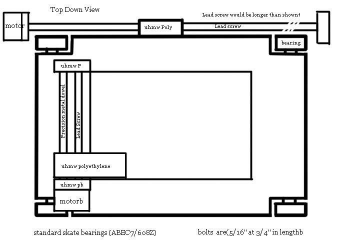
This would only be to position the negative carrier in the x-y directions. The carrier would still ride on a thick glass plate.
The idea is to use roller bearings to act as wheels and ride in slots on the negative stage. Perhaps using a precision rod as an axle would help with alignment. Another idea is to use uhmw polyethylene runners.
I'm also thinking of moving both of the steppers onto the sled. That way, the lead screw could push the sled from the middle instead of the side.
Suggestions?
-
Registered
Here's a Google Sketchup model of a potential linear positing system:http://dl.dropbox.com/u/3595413/sled2c.skp Please be kind, I just started using cad today. Everything is close to the proper scale.
The motors would be: CNC Stepper Motor Driver Systems & Hobby CNC Routers:: PROBOTIX™
The linear rails and bearing blocks would be: http://www.ebay.com/itm/160773515442...=p5197.c0.m619
-
Registered
You know you can make an easy CNC for this by using a cheap darkroom enlarger,this will be easy to convert.
-
Registered
-
Gold Member
Very cool...
Have you posted a blog entry somewhere with details of how you built it?
I think that I see some timing belts and pulleys as well as some supported rails in the video.
-
Registered
Most of the discussion took place on a photography forum...but that's very spread out. We'll consolidate info sometime soon.
In short, we use an Arduino Uno and two Easy Drivers to drive small stepper motors. See: Scanduino | Flickr - Photo Sharing!
The Arduino sketch is at:
https://github.com/nSomnius/Scanduino-by-ReallySmall
I used 4 - 450mm long SBR16 linear rails and 8 bearing blocks.
The system takes 25 pictures of a 4x5 negative using my D600. The images are then "developed" in a raw processor into 16-bit-per-channel tiffs, which are then stitched together.
-
Registered
Re: XY stage for dslr film scanner
Thanks for the article, it is very instructive. I found this website if you would like to read further infomation: XY stages, Coordinate table - All industrial manufacturers - Videos
-
Registered
Re: XY stage for dslr film scanner
Thanks for sharing! I came accross a very interesting website with more info on this product:
http://www.directindustry.com/indust...age-76555.html
-
Member

Re: XY stage for dslr film scanner
Nice, well done. I am very interested in a similar setup for scanning 35mm & 120 & 220 film.
- XY stage for dslr film scanner
Tags for this Thread
 Posting Permissions
- You may not post new threads
- You may not post replies
- You may not post attachments
- You may not edit your posts
-
Forum Rules


 Reply with Quote