Reply with Quote
wooww....thank you casainho.....
are PCB2GCODE is free software..??


Olá! Fixe! And hey - nice photo!
That's really great. I will definitely automate the inch / mm defaults now. Give me a few days - and thanks for testing it.
wooww....thank you casainho.....
are PCB2GCODE is free software..??
pcb2gcode it's Free Software. We can read on pcb2gcode.c file:
/* This file derives from gerber_to_gcode, which bears the
* following copyright. (My subsequent changes are GPL3.)
* -- cynbe at cynbe dot us
*/
/************************************************** *************************
* Copyright (C) 2004 by matthew *
* matthew_s@users.sourceforge.net *
* *
* This program is free software; you can redistribute it and/or modify *
* it under the terms of the GNU General Public License as published by *
* the Free Software Foundation; either version 2 of the License, or *
* (at your option) any later version. *
(...)
************************************************** *************************/
Last edited by casainho; 07-30-2010 at 05:07 AM. Reason: smaller text
You're welcome!Originally Posted by casainho

And thanks to Michael for adopting my little orphan idea :-)
Poul-Henning
Poul-Henning, it's a great idea... For me it makes it a lot easier to set boards up, you don't have to obsess about the board being absolutely flat, you can use a soft base under the board so you can etch, drill and mill without having to take the board on and off, the tool lasts longer and you get a nice clean etch, all over, even on a big board. I am going to be using it all the time.
Plus, I learnt how to program in Python, I know more about G code programming than I ever dreamt there was to know, and to cap it all, I now know what bilinear interpolation is!!!
Re the optimisation issue - on reflection, I think I will continue to use Opti_qt for milling, and Gopt for drilling. They both work really well. If a command line version of either or both appear we could do a onestop shop eventually, calling them from a eg a py script that runs the optimisation program(s) first, and then runs the optimised code through Etch_z_adjust...
Finally, where should I save it? I am not a programmer by trade (you may have noticed) but I do see that people tend to save files like this in some kind of repository, so updating down the track is not an issue.
Suggestions anyone?
First, I would say: don't try to solve a problem if you do not have it.
Just stick it on a homepage somewhere. (But please remember to make the version number part of the filename in that case, that is important for certain kinds of automatic tools used by people who do software distributions.)
If you want to do it "right", you can come up with a snazzy name and create a project for it on SourceForge.net, they host tons and tons of small software projects like that for free.
Or maybe ask the EMC2 wizards they may have an idea how to organize G-code related utilities ?
Poul-Henning
I suggest to use http://code.google.com/. I am being using also Sourceforge.net and code.google seems to be more easy/simple, however with less options(?), which is not relevant for this "small" project.
On code.google you may use SVN for version control (on sourceforge also) -- if you don't know yet SVN, go and read on wikipedia and even the examples of usage on code.google.
On code.google, you get a wiki that you could use to document, however I believe the best place to document all this is on EMC2 wiki. You could keep the code on code.google and the documentation (text and images, videos on www.blip.tv) on EMC2 wiki.
Ok, answering public the questions on may privately by e-mail:
Not sure what to do with the G64 issue, which looks like its a PCB2GCODE thing. (...) Maybe just a warning to make sure there are no other G codes between the first G01 statement and the data???
Maybe you could give me some words to put in the intro to tell people how to work around that?
Don't worry about G64 and G61, pcb2gcode have an option where it does not output that codes: --max-deviation=0
I think the most important is to distribute an example GCode file where your code works, including the result file, so people can go and see the changes and compare.
I am not finding free time to document this on EMC2 wiki, can you do it?
I started documenting here: http://wiki.linuxcnc.org/cgi-bin/emc...Height-Probing
Read this page to know how to edit that wiki pages: http://wiki.linuxcnc.org/cgi-bin/emcinfo.pl?BasicSteps
I need to know how to use images there.
Michael, try the command line file I've attached. Just needs the nput filename with a .nc extension. Also, I'll PM you my email so we can pass the file back and forth easier.
-Jay
Ok, I played with this Python on Windows. Long story short the probing subroutines won't work in Mach (2000 sub routine limit).
On another note, I don't see that it would be difficult to incorporate the python additions/modifications into the C code. just adding the subroutine definitions and adding the
O200 call [x1] [y1] [aa] [bb]
Mike, I may need to pick your brain on this so I understand the subroutine stuff ... it's new to me.
-Jay
Just had a look at the Mach manual at: http://www.machsupport.com/docs/Mach3Mill_1.84.pdf
In the manual they always use G1 (not G01) - maybe that is an issue?
The probe command and the probe parameters definitely look like they are an issue. (See 10.7.12 Straight Probe - G31 on pages 10.20 and 10.21 of the manual)
The probe command for EMC is G38.2, for Mach it is G31.
Also, when the probe trips, EMC puts the X, Y, Z values for the current probe position in #5061, #5062 and #5063, whilst in Mach it looks like they use #2000, #2001 and #2002
(Why can't they all just be friends!?!)
The G38.2 code and the read from #5063 in Etch_Z_adjust.py both occur once only in the G code O100 probe subroutine - try changing them to the values above and see if it works.
If that works, it means you would only be able to probe a max 1000 points in Mach - but I can't imagine a situation where you would ever need to probe that many points, for this particular application anyway...
M
Also looks like you can't do if or while statements in Mach G code.
Not insurmountable - just have to do all that stuff in the etch optimisation program and output explicit G code (not branching G code) that tells the mill every step to do, one by one, for the probe grid and then for the etch moves including adding extra way points for the longer lines.
Will be a longer output file but it will work.
There are experimental packages of EMC2 for actual Linux Ubuntu 10.04! -- I was keeping another partition for Ubuntu 8.04, 2 years old! oh man, in 2 years many things were improved...
Latest version of Etch_Z_adjust... does the Etch_Z_adjust trick, now equally well in either inch or mm G code. It will ask you what units you are using first.
I tried automating the units selection, but it was too fiddly to get it to exclude G21 or G20 codes that were included in comments, easier just to ask.
It works in my EMC set up - but let me know how it works for you.
(After downloading, change the .txt extension to .py so it runs in Python).
Looks to me that it does work :-)
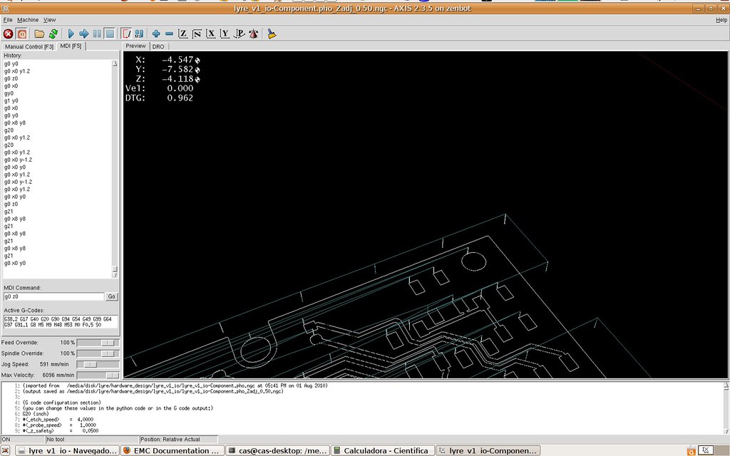
I need to mill a board however my blank board is almost the size of the board I need to mill. Unfortunately your probing code makes the need to more board and so I can't mill the board. Could you please add an option to probe just inside the area of the board to mill?
NOTE: I start by losing blank board just for fixing it to CNC table.
Here a screenshot showing the question:
Last edited by casainho; 08-01-2010 at 05:04 PM.
The bilinear interpolation formula only works if the point to be estimated is inside a grid cell of four known points - outside that cell, it can't estimate.
To get the grid size to the smallest size, you would have to work out a grid size that is only the slightest bit larger than the work. The grid size will be very slightly larger than (Xmax - Xmin) divided by some integer, and very slightly larger than (Ymax -Ymin) divided by (probably) some other integer. You may have to try a few integers for each axis to get a cell size that works for both X and Y axes.
To make it easier, you could also try supergluing the PCB to a larger backing board. With this new, cutting edge software you are now using it won't matter that the PCB isn't perfectly flat.
See how you go. Até logo!
So, let's forget bilinear interpolation on edges of the board. There must be a way to use the Z probed values of edges of the board to mill it referring to that values.
I went and tried to change your code however I can't understand it all, mainly the GCode probing routine/variables and logic/math...
It's difficult because you have a fixed step size for both axis and my board have different sizes for each axis...
That means even more work... right now It takes a lot of time to try have a double side board working... I would prefer that code would just probe the final PCB area.
Can you please think on it? maybe do a quick hack on actual variables and share with me? I will test and even try to put it working If I can.
Yeah, I am Portuguese, and you? ;-) -- até mais logo ;-)
The grid has to be in squares for the bilinear interpolation to be accurate. So you can only get one dimension really accurate. And the grid boundary must be outside the work.
Use the dimension that has the least room as the basis for calculating grid size: eg if the Y dimension is tight, use that one.
If Ymax - Ymin = say for example 61.6, use a grid spacing of 6.17, this will give you a grid that is only 0.1 mm bigger than the work's Y dimension.
There will be more overlap on the X dimension - but it won't be more than 6.17/2 = 3.09mm at the most (and probably less)
And so the linear interpolation wouldn't work? -- I believe no one wants to spend blank PCB nor do such calculations.
http://en.wikipedia.org/wiki/Linear_interpolation
http://en.wikipedia.org/wiki/Bilinear_interpolation
The most pcb you would waste is half the grid size on each size of the work... but here's some work arounds:
(1) Try using 0.2695 inches as your grid size. That will give you a 9 x 14 grid that is 61.6 x 95.8 mm - pretty tight
(2) The etch track that is causing the problem on your board is the one that runs round the perimeter of the board... Can you mill that one separately? Remove it from your Gcode file and etch it separately - and don't use etch adjust for that track??
(3) Finally, I have to say, when I make these things I always use a blank PCB that is bigger than I need, (PCB is not that expensive) so I can fix it easily. We're making prototypes and one offs right? Anything going into production you would send to a board house.
I etch the board first, then drill any holes, then finally mill around the external edges to cut the board out - as a final step. If I'm being really finicky I stop it half way through the cut and tape the over the first cuts so the board won't move when the final cut is made. Apart from anything else doing it that way means that the tracks and drills are always perfectly aligned with the edges of the board.
Sorry I can't be more help on this just now. What you are asking is possible, but - I wrote the bilinear regression stuff a couple of months ago now and it would take a while to get my head round it again... and I don't have that time for a few days now. If you're still having problems I can have look at it again next weekend.
 Posting Permissions