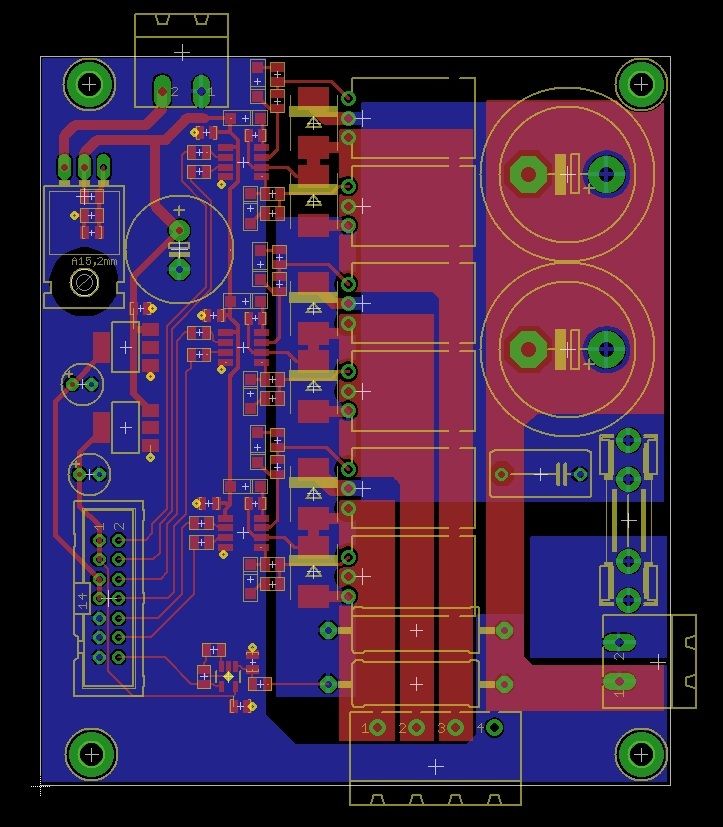
First, I will draw separate the logic and power section
power section will include two types, type use to220 fet and t265 fet type
to mihai, can i use opam for current senser, we can reduce shunt resistor value
b.r


That might be even better.Originally Posted by James Newton

Jeff...
Patience and perseverance have a magical effect before which difficulties disappear and obstacles vanish.
First, I will draw separate the logic and power section
power section will include two types, type use to220 fet and t265 fet type
to mihai, can i use opam for current senser, we can reduce shunt resistor value
b.r
Last edited by tivoidethuong; 10-30-2015 at 09:33 PM.
Hi!
The PCB of tivoidethuong is looking very nice, power section looks very cleanly laid out!
I posted my power layout already couple of posts ago. The control board design was also finished a while ago. I sent both PCB:s to fabrication less than a week ago and just checked that they have been already mailed to me, so I think I'll get them in a week or two.
Unfortunately I had to make a few changes to schematic so Mihai's firmware won't be compatible out of the box, but requires change of a few pin and timer definitions. I had to do that to make the board compatible with my own requirements (HALL sensors mostly).. But when I get the boards I'll make the required changes to the code and try it.
Design of the control board:
http://pekka.eu/cnc/bldc_control_sch.pdf
http://pekka.eu/cnc/bldc_controller_layout.png
I mostly understand the desire to use pre-assembled devboards to avoid SMD soldering, but as I'm designing this primarily for myself at least for now (sorry for being selfish) I won't go that way as for me that is not the difficult part.
Have a nice weekend!
Pekka
Hi,
its possible to use this current sensor module for isolated current sensing?
Thanks
Hans
please advice part you want
b.r
The pdf says:
The ACS712 outputs an analog signal, VOUT . that varies linearly with the uni- or bi-directional AC or DC primary sampled current, IP , within the range specified. CF is recommended for noise management, with values that ACS712-DS, Rev. 15 depend on the application.
So yes... It can be used... You will only have to change some calculations in the code....
Mihai
Hi Mihai,
many thanks for your answer. Please don't be afraid about my ideas. I don't know it's possible, but my idea is to split the servo drive in a controller part and a completly from the controller part isolated power part. So you can work with high voltages (up to 600Volts) on the power side.
I am not able to make changes in the code, but I want to create the 2 pcb's and show them here in this thread.
Hans
Good ideea with the separation. Hovever up to 600V sounds scarry. Extreme precautions and perfect separation must be enusred... Also... The IR2101 must be changed I guess... Probably pwm outputs from the mcu must be separatwd by optocouplers too... Not sure... Never done such high voltage circuit. However I think it's possible... If you need any change in the firmware just ask... I'll try to help...
Mihai
Hi Mihai, Great project, I thought I'd have a go at building it. I've ordered a STM32F103C8T6 module and parts to make the driver for a DC servo.
A quick question, My DC servo operates at 75v, would I need to change any components in your driver circuit to run at 75v?
Cheers
John
Voltage for C4. That should be all...
Mihai
Fixed some bugs related to firmware upgrade. (please just try to upgrade with dfu files)
Fixed a bug related to motor not moving anymore after a Stop / Start sequence
Please also note the new Flash and Memory structure of the app:
RAM (xrw) : ORIGIN = 0x20000000, LENGTH = 19K
RES_RAM (xrw) : ORIGIN = 0x20004C00, LENGTH = 1K
BOOT (rx) : ORIGIN = 0x08000000, LENGTH = 12K
FLASH (rx) : ORIGIN = 0x08003000, LENGTH = 52K-1K
DATA (RWX) : ORIGIN = 0x0801FC00, LENGTH = 1K
19 k of ram available for app... in last 1k I added a variable that is read by the bootloader in order to see if it needs to enter DFU mode after reset or not.
12k of flash for the bootloader. Although it seems to be smaller I think we still have enough for application. (note that the hex file obtained now by compiling starts at 0x08003000). Flashing only the app wont start...
51K for app.
1k for servo settings... Please note that the settings are journaled, they are written one after the other until whole page is filled and only then the page is erased
Enjoy
Mihai
Last edited by mcm_xyz; 11-01-2015 at 02:10 PM.
One more little question... Anyone knows a good and cheap source or has a bulky DC motor he could spare?
I have some extra encoders (for a 5mm shaft) that I could use to make a DC Servo Motor. I want to start modifying the code in order to be able to configure this drive to work with both BLDC and DC motors...
So basically I need: either a very cheap DC servo, either a DC motor that I can adapt...
Thanks for help!
Mihai
Hi,
here is the first design of the controller part.
Thanks
HansFreqCont.jpg
Nice!
But please please please!!! Build something smaller first! I don't want to set your garage on fire...!!!
I'm sure even the hcpl3180 optos you added there cost a lot...
Mihai
Hi Mihai,
maybe I can build the pcb some smaller, but I will produce the prototype with isolation milling. I think the power-pcb is 100 x 60 mm, so both parts has europaformat. Can the Arm reads a thermoelement type K directly, is there a internal multiplicator for the analog inputs build in? Its possible to program an outputpin to enable the integrated powerbridge. I have orderd the optos in China and they are very inexpencive. Quality?
Thanks
Hans
i Mihai,
do you know an other high speed optocoupler with positive logic?
Thanks
Hans
6n137 high speed opto
Hi,
the 6N137 has a inverted logic. I orderd the HCPL3180 from China for 1$. I do not know about the quality, when I receive them I will test.
Hans
HCPL3180 is mosfet gate drive opto, you can direct drive mosfet
gud choice