TB6564AHQ (THB6064AH) PCB design - Page 5

Page 5 of 5 FirstFirst ... 2345
Results 81 to 98 of 98

Thread: TB6564AHQ (THB6064AH) PCB design

  1. #81
    Gold Member
    Join Date
    Jan 2005
    Location
    Toronto, Canada
    Posts
    1695
    Downloads
    0
    Uploads
    0

    Default

    You can run the 5.6 amp motor at 4.5 amps with no problem. The current is controlled by the drive. The holding torque will be scaled down accordingly.

    How did you calculate the power?


  2. #82
    Registered paulus.v's Avatar
    Join Date
    Jan 2013
    Location
    Romania
    Posts
    21
    Downloads
    0
    Uploads
    0

    Default

    Quote Originally Posted by H500 View Post
    The holding torque will be scaled down accordingly.
    Of course it will be scaled down, which means I will not be able to run the machine as fast as I wish, but I hope it will be fine until I'll upgrade to 7A gecko drives.
    Quote Originally Posted by H500 View Post
    How did you calculate the power?
    There is a very good excel calculator with detailed explanations on the UK forum here


  3. #83
    Registered
    Join Date
    Dec 2009
    Location
    Philippines
    Posts
    69
    Downloads
    0
    Uploads
    0

    Default

    Hi,

    I have the HobbyCNC motors (425oz in, 3Amp, 4.2V, 3.2mH) fed with 36V. What would its oz-in rating will be if I use the thb6064 driver with it?

    Thanks in advance.

    Jordan

    P.S. I'm still a newbie.


  4. #84
    Registered paulus.v's Avatar
    Join Date
    Jan 2013
    Location
    Romania
    Posts
    21
    Downloads
    0
    Uploads
    0

    Default

    The holding torque will be the same as long you will give the 3A per phase respective 4.2A peak from the driver. But the torque will drop more rapid if you give less voltage. For your 4.2V and 3.2mH i guess you will get the best torque vs. speed with 60-70V. The THB6064 will be almost fine if run at 48V. 36V is not enough for your motors (this means the torque will drop rapidly with rpm).

    This is just my opinion, I'm not an expert.

    Hope it helps.


  5. #85
    Registered
    Join Date
    Dec 2009
    Location
    Philippines
    Posts
    69
    Downloads
    0
    Uploads
    0

    Default

    Quote Originally Posted by paulus.v View Post
    The holding torque will be the same as long you will give the 3A per phase respective 4.2A peak from the driver. But the torque will drop more rapid if you give less voltage. For your 4.2V and 3.2mH i guess you will get the best torque vs. speed with 60-70V. The THB6064 will be almost fine if run at 48V. 36V is not enough for your motors (this means the torque will drop rapidly with rpm).

    This is just my opinion, I'm not an expert.

    Hope it helps.
    Thanks for the quick reply. I have the 36V at hand and exchanging the transformer to arrive at 48V would be easy. Even then, this driver is still the best alternative for the Gecko540 IMHO.


  6. #86
    Gold Member
    Join Date
    Jan 2005
    Location
    Toronto, Canada
    Posts
    1695
    Downloads
    0
    Uploads
    0

    Default

    Don't use 48v. You will likely fry the board. The maximum safe value is about 42v.


  7. #87
    Registered
    Join Date
    Dec 2009
    Location
    Philippines
    Posts
    69
    Downloads
    0
    Uploads
    0

    Default

    Quote Originally Posted by H500 View Post
    Don't use 48v. You will likely fry the board. The maximum safe value is about 42v.
    Oh.. Thanks for the warning. It really pays to do your research/ask questions before buying/building.


  8. #88
    Member
    Join Date
    Jan 2005
    Location
    Belgium
    Posts
    364
    Downloads
    0
    Uploads
    0

    Default

    Quote Originally Posted by j2sip View Post
    Oh.. Thanks for the warning. It really pays to do your research/ask questions before buying/building.
    There are more factors to consider: What kind of machine are you building and what will it be used for?

    A high acceleration is more important than very high rapids for a lot of applications especially for small moves.
    High speed doesn't give you anything if it takes seconds to get there.
    In these cases the motor power at low RPM is more important than the drive voltage for rapids.

    It all depends on your machine, a large wood router needs speed, a small mill is better with fast acceleration.


  9. #89
    Registered
    Join Date
    Dec 2009
    Location
    Philippines
    Posts
    69
    Downloads
    0
    Uploads
    0

    Default

    DIY CNC router Build log Sorry, mostly in our language.

    It has a 40"x30" cutting dimension. It can go 250IPM on all axis but have set it to 200. More than 20 acce in mach3 makes it vibrate. I'm in the process of improving the carriage. though. And changing the hobbyCNC drive to a more capable drive design, too: YOURS! If only I'd checked james newton's site before buying the hobbycnc kit..

    It'll be cutting electric guitar bodies and neck and jigs and fixtures for local furniture shops.

    Thanks.


  10. #90
    Registered
    Join Date
    Jan 2008
    Location
    Netherlands
    Posts
    13
    Downloads
    0
    Uploads
    0

    Default

    Hi guy's,
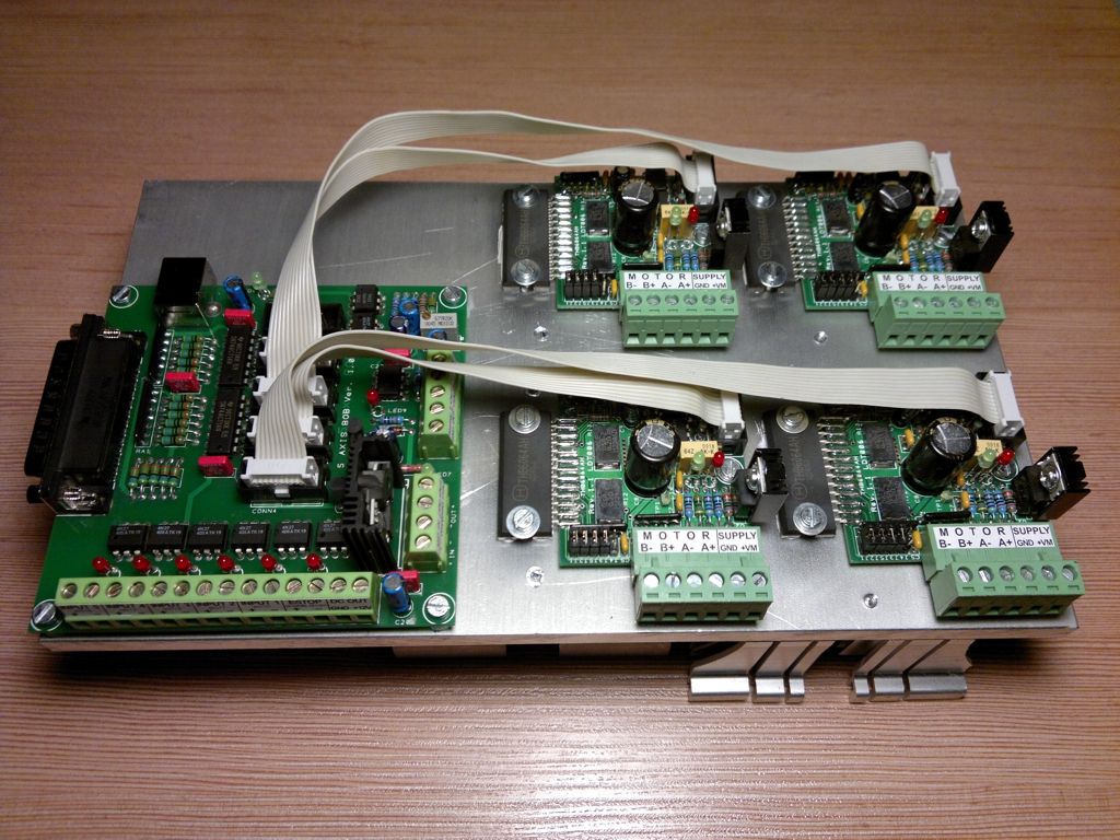
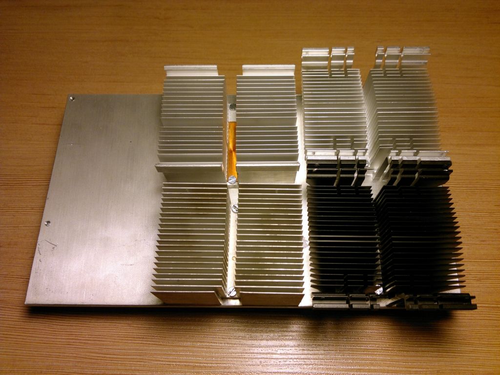
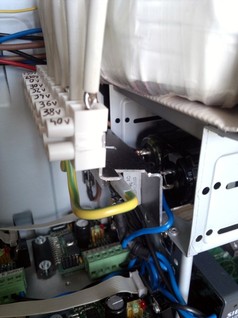
    I've been working on a replacement control box using Luc's kits recently for a Chinese 6040 router.

    I posted my results here (which are pretty good :-) ): http://www.cnczone.com/forums/chines...q_drivers.html


  11. #91
    Registered
    Join Date
    Dec 2009
    Location
    United States
    Posts
    61
    Downloads
    0
    Uploads
    0

    Default

    I'm about to build my first cnc mill and would love to use this driver.

    Would it be possible for to get a SMD version for ease of assembly or the gerber files so I could remake it using smd components?


  12. #92
    Registered paulus.v's Avatar
    Join Date
    Jan 2013
    Location
    Romania
    Posts
    21
    Downloads
    0
    Uploads
    0

    Default Re: TB6564AHQ (THB6064AH) PCB design

    Hello,

    I have just wired everything, and set the Vref at 2V with the running motor (I have the special rev.1.1 drive) and I got a ridiculous motor torque. Then I turned up the VR1 until I got a drive fault. I ended up with the Vref at 3V running without fault. I did a lot of jogging and the chip and motor haven't warmed up (about 30 °C). The torque is now a little higher but still not impressive. Now I am asking what represents the maximum of 4.5A of the chip specs? I have measured the input current of the drive and Was far bellow that 4.5A. Here are the measurements:

    decay mode standby Vref standby current running Vref running current input voltage
    20% 1.68V 0.33A 2.97V 1.3A 45.3V
    80% 1.68V 0.4A 2.97V 1.4A 45.3V

    Shouldn't the drawn current be closer to the 4 Amps chip rating?


  13. #93
    Member
    Join Date
    Jan 2005
    Location
    Belgium
    Posts
    364
    Downloads
    0
    Uploads
    0

    Default Re: TB6564AHQ (THB6064AH) PCB design

    Quote Originally Posted by paulus.v View Post
    Shouldn't the drawn current be closer to the 4 Amps chip rating?

    No, it's difficult to explain so very simplistic: Let's assume you have a 3V, 4A per phase motor:
    The maximum total power would be 3V * 8Amp = 24W at full step with both phases on.
    You are using a 45V supply, if the drive would draw 4 Amp from the supply this would be 180 Watt to be dissipated in the motor and drive.. way to much.
    The drive regulates the motor current by switching the supply on and off at a very high rate to match the current set by the Vref voltage.

    How do you evaluate the torque? At what motor speed (RPM)?
    Do you have the specifications for the motor you are using?

    Open source CNC electronics and accessories:
    http://home.scarlet.be/ldt006/THB6064AH.html


  14. #94
    Registered paulus.v's Avatar
    Join Date
    Jan 2013
    Location
    Romania
    Posts
    21
    Downloads
    0
    Uploads
    0

    Default Re: TB6564AHQ (THB6064AH) PCB design

    I was thinking that probably the output voltage and current is different from the input but then why the psu is calculated by the motor amps rating? And I ended up with a huge toroid.

    My stepers are longs-motor nema34, 66mm length, 4A, 0.6¦¸, 1.6mH, 2.2Nm. My router is moving 16mm/ motor rotation. The drive is set to 1/10 microstepping. At 50IPM I can push about 35kg before stalling, at 100IPM some 25kg. Just now the rapids speed is impresive. 400IPM without stalling. Tho days ago was only 170IPM. The only difference I notice is the input voltage rise at 47.1V. The drive is running very cool without a fault and still with 3V at Vref.

    Not sure what's going on...


  15. #95
    Member
    Join Date
    Jan 2005
    Location
    Belgium
    Posts
    364
    Downloads
    0
    Uploads
    0

    Default Re: TB6564AHQ (THB6064AH) PCB design

    The PSU current is calculated from the motor current: There's enough margin if you take +-2.5A for a motor with 4A/phase.
    How did you calculate it?

    The 47V is high, you are dangerly close to the absolute maximum, 40V is enough for your 1.6mH motors assuming they are 4 wires.
    3V at vref is to high also, it should be 2.4V for 4Amp.
    How are the chip's cooled? They should be quite warm at 4A without active cooling or massive heatsink.
    The chip is able to drive these motors at full power without problems but 16mm/rev is high and 2.2Nm isn't extremely strong.
    I'm running a 4Nm on a 5mm/rev ballscrew for 10.000mm/min (=400IPM) with these drives.

    Are the mechanics OK, everything properly aligned?
    I would look to install a belt or other reduction between motor and screw if you need more torque.

    Open source CNC electronics and accessories:
    http://home.scarlet.be/ldt006/THB6064AH.html


  16. #96
    Registered paulus.v's Avatar
    Join Date
    Jan 2013
    Location
    Romania
    Posts
    21
    Downloads
    0
    Uploads
    0

    Default Re: TB6564AHQ (THB6064AH) PCB design

    Quote Originally Posted by lucas View Post
    The PSU current is calculated from the motor current: There's enough margin if you take +-2.5A for a motor with 4A/phase.
    How did you calculate it?
    Yes this is the way I have calculated, 60% if the motor amps. But now it is at 35%. I am curious if at lower voltage the drawn current will rise. Will check later.

    Quote Originally Posted by lucas View Post
    The 47V is high, you are dangerly close to the absolute maximum, 40V is enough for your 1.6mH motors assuming they are 4 wires.
    3V at vref is to high also, it should be 2.4V for 4Amp.
    I will lower the voltage and the output current to see how much it will affect the torque. What could happen if I let the Vref at 2.7V, the 4.5A absolut maximum? I see from the chip specs that the over current protection is only at 6A, so I could go to 3.5V at Vref without fault

    Quote Originally Posted by lucas View Post
    How are the chip's cooled? They should be quite warm at 4A without active cooling or massive heatsink.
    Yes I have massive heatsink and active cooling

    Quote Originally Posted by lucas View Post
    The chip is able to drive these motors at full power without problems but 16mm/rev is high and 2.2Nm isn't extremely strong.
    I'm running a 4Nm on a 5mm/rev ballscrew for 10.000mm/min (=400IPM) with these drives.

    Are the mechanics OK, everything properly aligned?
    I would look to install a belt or other reduction between motor and screw if you need more torque.
    Probably I will be fine with my configuration for woodworking and I will consider changing the pulley ratio to 6.4mm/rev for occasionally aluminium milling.

    My linear guides are not very efficient and the whole machine is massive, the gantry weights about 100kg. I have choosen this motor/drive configuration only to fit my budget, I will upgrade it as soon as I will have the money, and use this ones for a much smaller machine.


    Last edited by paulus.v; 03-31-2014 at 07:00 AM.


  17. #97
    Member
    Join Date
    Jan 2005
    Location
    Belgium
    Posts
    364
    Downloads
    0
    Uploads
    0

    Default Re: TB6564AHQ (THB6064AH) PCB design

    Quote Originally Posted by paulus.v View Post
    Yes this is the way I have calculated, 60% if the motor amps. But now it is at 35%. I am curious if at lower voltage the drawn current will rise. Will check later.
    The current will increase with a lower supply voltage especially at low speed and when accelerating. That 60% rule still leaves a bit of margin.

    Quote Originally Posted by paulus.v View Post
    I will lower the voltage and the output current to see how much it will affect the torque. What could happen if I let the Vref at 2.7V, the 4.5A absolut maximum? I see from the chip specs that the over current protection is only at 6A, so I could go to 3.5V at Vref without fault
    Donno what will happen in the long run, the drives have been tested and used briefly at the maximum rating and above, none have blown doing this.
    I personally think that 4.5 Amp should work but using a 48V is much more risky.
    It's up to you but don't blame me if the smoke escapes.

    The gantry weight doesn't have much influence on the max. speed but only on the acceleration. Misaligned screw and guides do decrease the max speed but I think yours are fine considering the 400IPM obtained.

    Some pics of the machine?

    Open source CNC electronics and accessories:
    http://home.scarlet.be/ldt006/THB6064AH.html


  18. #98
    Registered paulus.v's Avatar
    Join Date
    Jan 2013
    Location
    Romania
    Posts
    21
    Downloads
    0
    Uploads
    0

    Default Re: TB6564AHQ (THB6064AH) PCB design

    Some more tests..

    input voltage output current max rapids
    42.2V 4A 160 IPM
    42.2V 4.5A 250 IPM
    42.2V 5A 320 IPM
    45V 4A 230 IPM
    45V 4.5A 300 IPM
    45V 5A 370 IPM

    I will go with 4.5A at 45V for now and if will not need that force or speed for woodworking I will tune them down. I noticed that with each running motor the voltage will drop 1V. Anyway yhe line voltage fluctuates a bit and the 48V was the maximum I think (Sunday night). At 244V it was over their margins (220V +/-10%). I bought a panel voltmeter with alarm, I'm still waiting to arrive.

    I had a good idea to order the toroid with more secondary outputs. It was only 2% of the price for each additional one and it is definitely worth it.

    Quote Originally Posted by lucas View Post
    It's up to you but don't blame me if the smoke escapes.
    When I have read your posts one year ago I realised you are a very good electronics engineer, or how it's called. So I won't blame you for anything and I'm sure your designs will endure more

    As soon as the build is ready I will have time update my build log with pics and details.


Page 5 of 5 FirstFirst ... 2345

Tags for this Thread

Posting Permissions

  • You may not post new threads
  • You may not post replies
  • You may not post attachments
  • You may not edit your posts
  •  


About CNCzone.com

    We are the largest and most active discussion forum for manufacturing industry. The site is 100% free to join and use, so join today!

Follow us on


Our Brands

TB6564AHQ (THB6064AH) PCB design

TB6564AHQ (THB6064AH) PCB design