
 Reply with Quote
Where to buy them;
I bought them from Farnell, they were $3 each in the catalogue but when I phoned to order they were only 78 cents each.
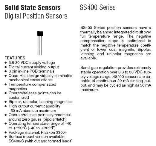
311-1477 Honeywell SS441A SENSOR, HALL EFFECT
Datasheets;
SS441 Datasheet;
Honeywell SS441 Hall Switch.pdf
SS541 (surface mount version) Datasheet;
Honeywell SS541 Hall Switch.pdf
How to test the sensor.
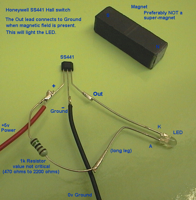
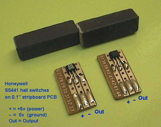
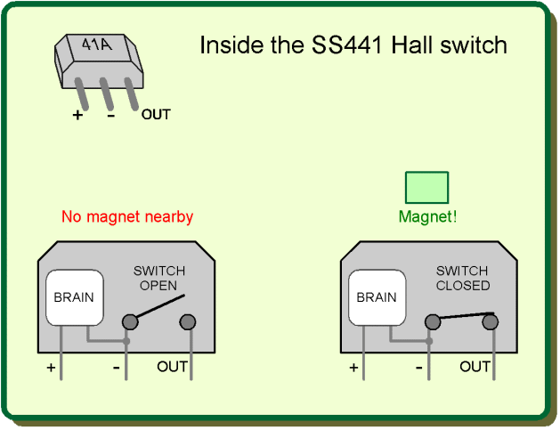
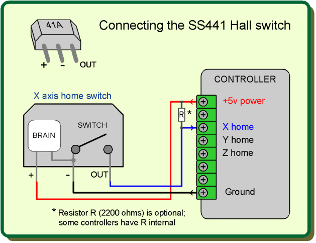
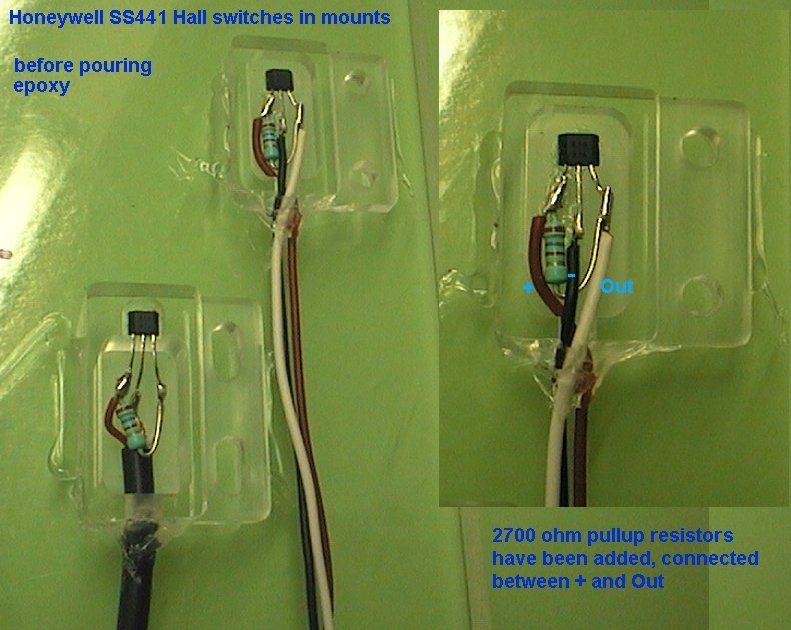
The SS441 and SS541 have 3 legs;
+ (+5v power)
- (0v ground)
O (Output)
The datasheet says 4v to 30v is ok for power, but I used +5v regulated as that is available on my CNC machine (and most machines) and using regulated voltage for the power eliminates one variable that might affect the sensing characteristics.
The easiest way to understand these sensors is to see the output like a switch to ground, whenever the magnet is present.
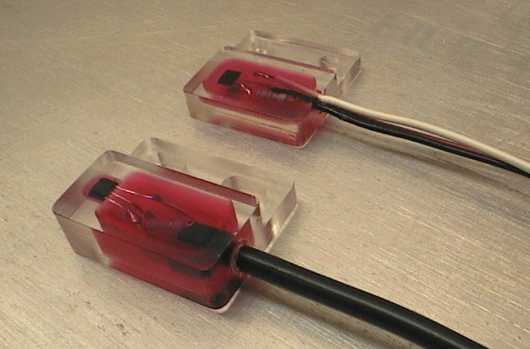
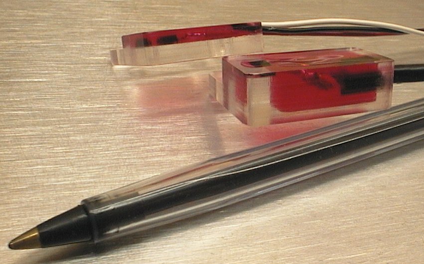
This is a very simple test rig that only needs a resistor and a LED. When the magnet is present the Output leg switches to ground and the LED lights up. The test rig took about 30 seconds to make, and was powered from +5v and ground via the Red and Black wires.
Test rig results
This worked well. I used a 1.5k (1500 ohm) resistor and a high brightness LED but the resistor value is not critical nor is the type of LED.
The sensing surface of the SS441 is the front (or back) face. When a magnetic South field is present near the front face it switches on (Output connects to ground). Likewise it switches on the same if a North field is near the back face of the device.
The front face has the writing and sloped sides. The back face is flat.
I tested a few magnet types and settled on 2 small bar magnets that operated the sensor from about 5mm (3/16"). Hysteresis was about 3mm (1.8") or less.
Hysteresis means that once the sensor turns on, the magnet must be withdrawn a certain distance for it to switch off again.
Using a lower strength magnet means the magnet must be closer to activate the sensor, and the hysteresis is much smaller, and the repeatability of the "on" trigger point is better as this is over a smaller physical distance.