Reply with Quote
When I asked Mikini about tramming, they said that it didn't need it and that there are no ways to do it outside of their facility and that the end user should never attempt it. I never felt it needed it but I never really carefully checked.


Hello folks, As I have mentioned in another post, I recently finished my first set of parts on the mill. Although I was happy in getting them done, I just didn't think the finish was up to snuff. By that I mean, the parts had a somewhat dished look (concave) about them. I checked this using a precision straight edge and a flash light. Sure enough you can see light come through in spots.
Anyway, I never really checked the tram on the mill, so I decide now was the time. Before I jumped into anything, I researched all I can about tramming. I found Hoss's videos very informative...Here's part #1
http://www.youtube.com/watch?v=40Q61UAnOTA]G0704 Tramming Part 1.wmv - YouTube
I started by checking the spindle to the column, using the RDM method used in the above video. My drill rod measured 8". I started at the top...centered my "0" and moved down to about a half inch from the end of the rod
The spindle was out by .002 fore and aft. I needed to shim the front of the spindle.
The Mikini really doesn't have any place to place a shim, other than under the spindle. As the head is bolted directly to the linear bearings. So I loosened the 6 Allen bolts that hold the spindle in place and gave the spindle a light tap downwards. This gave me enough room to place a .001" shim between the spindle collar and casting. Also, the shim is only .250" wide x
.750" long....only about .250" is inserted into place..the rest is used as a handle
I rechecked the runout and all was good, as I had even readings on my dial test .
Now it was time to check the left and right runout. Here I was out close to .0045" out of trueThe shims were installed on the left side of the spindle. The best I could get was about .00003" runout at the bottom of the rod. Which isn't to bad for what I do.
Now it was time to tram the head to the table. Btw, I'm using the same setup as Hoss has in his videos.
I started out checking the front to rear. Here I was out by .004" , the odd part here is that it was leaning backward. Normally, you would think the mill would nod forward. Anyway, I loosened the six large Allen head bolts at the base of the mill ( I used a ratchet with an Allen wrench socket )....just enough to be able to rock the mill and place shims on both sides of the rear....about .0025" in this case.
After getting even readings front to back....I checked my left to right position...again I was out by .0045". I needed shims placed on the left side of the column. After all was said and done, the only spot with no shims was the front right corner ....
Being that I'm a rank beginner at this milling stuff, the above took me about 6 hrs to accomplishBut, it was worth it..... I made the Mikini a bit better and exercised this old man's brain cells a bit
Similar Threads:
- Tramming
- Tramming X & Y
- tramming (X2)
- Need Help!- Tramming
- tramming
pete
When I asked Mikini about tramming, they said that it didn't need it and that there are no ways to do it outside of their facility and that the end user should never attempt it. I never felt it needed it but I never really carefully checked.
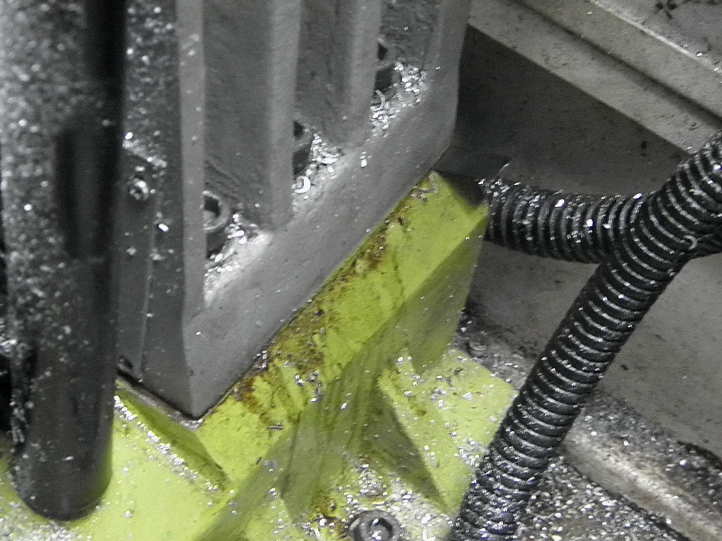
Here are some pictures of where i installed the shims.
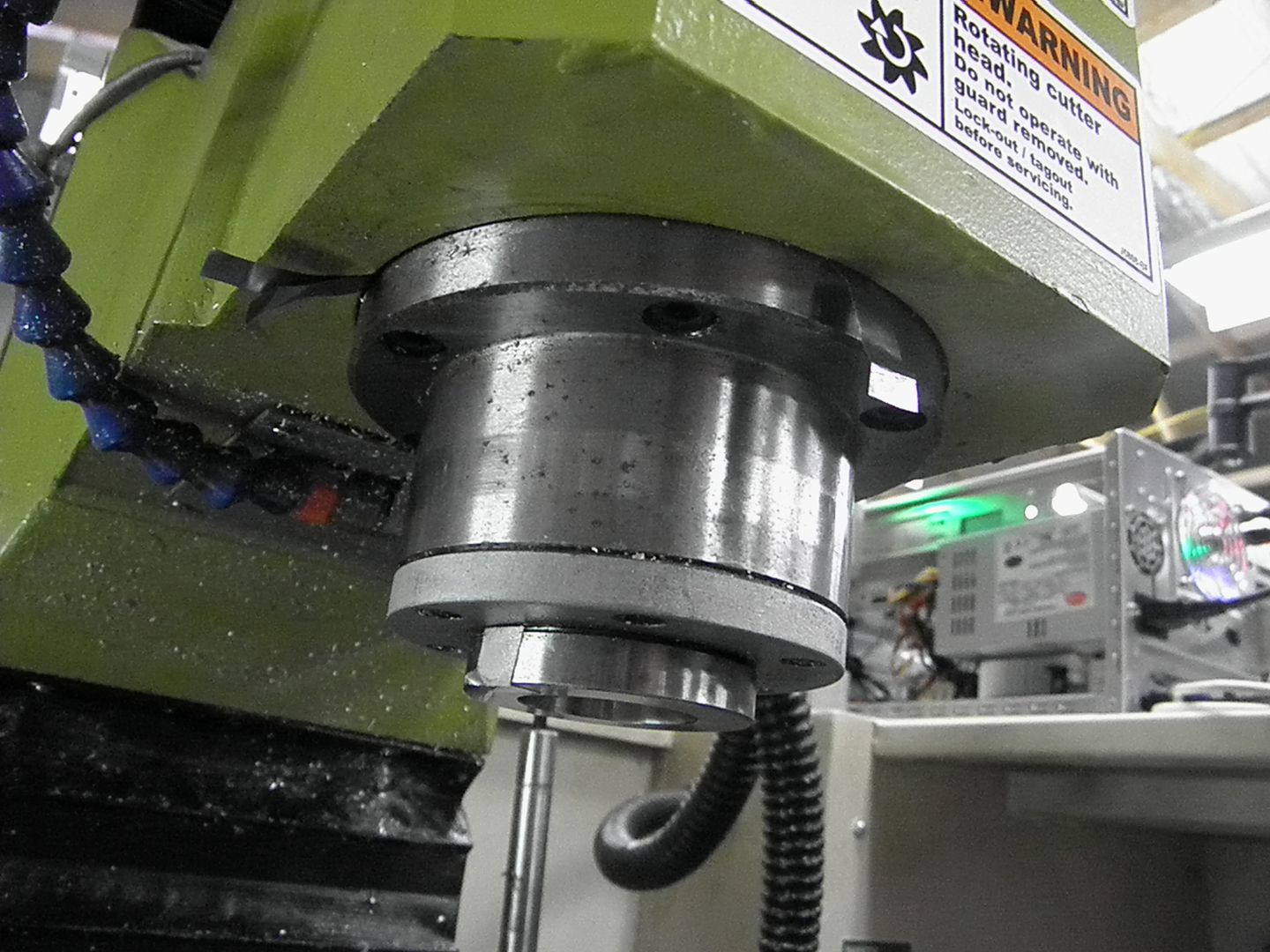
Here is the spindle .....
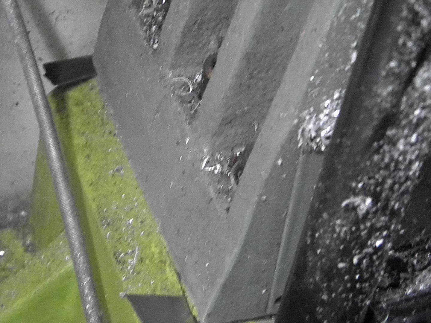
and at the base of the column....
I've also put together another computer...you can see it in the first pic. It's a Shuttle computer case, that I modified to accept an Intel mini itx mother board...similar to what Allen has in his retrofit. I also mounted the second breakout board inside the computer case...as well as my smoothstepper
I had issues with the smoothstepper and my spindle control initially, but, I believe by installing it inside the computer case and using the computers ground and such... sorted out my electrical noise problems with the smoothstepper.
I'm really impressed on how smooth the steppers run, very noticeable
pete
I have a story from yesterday that is relevant to this thread. I began the day trying to square up some stock for fixture plates and cutting into smaller blocks for parts etc. I tried facing the bars but something wasn't quite right. The face mill was leaving trailing marks on the surface, which it never has before. Then I notice the after facing two adjacent sides the bar would wobble when placing it against vice jaw so something wasn't right there either. I first suspected a stray chip preventing it from sitting flat but even after thoroughly cleaning all the surfaces as well as the bar and filing off the bead off the edge it was off square about .01 over 3 inches.
So I figured that since I repositioned the vice the night before I must have got a stray chip under it making it slightly off square. So I removed the vice and since I needed to do a very short job with the vice on it's side I though this would be a good time to do it since I'm taking the vice up anyway. So I did that job but it had a terrible surface finish which was quite odd. I noticed that when starting the spindle it kind of looked like the .25 endmill was wobbling in the ER collet chuck, but I assumed it was because the endmill had some Al marks on it so it was an optical illusion. Then when I removed the tool I noticed the drawbar wasn't tight even though I know I tightened it as I always do.
Anyway I went ahead and re-positioned the vice normally after carefully cleaning all the surfaces, and resumed facing the stock bar but the problems persisted. Not square with trailing marks and a worse finish. So I thought maybe the vice itself isn't square as in the fixed jaw to the bed, but I confirmed it was square with a 1-2-3 block. Totally perplexed I got out the 3D taster and began precisely measuring the square on all surfaces of the vice as it relates to the spindle. It was perfectly square on all axes to at least within .0001, in other words there was no perceptible movement of the needle on the dial.
So I determined that the only possible variable is the facemill itself is somehow not cutting square so I took the tool out and inspected it but I didn't see anything obviously wrong with it. Then I inspected the taper spindle bore and lo and behold there was a dent in the face of it that caused a slight bulge in the front edge of the taper. So I carefully filed it down and smoothed it out with some fine sandpaper and steel wool and reloaded the tool and cut a pass. Finally no trailing marks and a perfectly glass smooth finish. That also explains the poor surface finish with the endmill and the strange wobbling. I ran out of time to face an adjacent side to check square but it should be good now, I'll check next time.
Thinking back to the day before I recall changing a tool and what might have caused the dent. After unscrewing the drawbar the tool normally sticks but this time it just fell out on it's own weight (heavy tool). I was holding it but wasn't prepared for it to freefall so it came all the way out before I jerked it back up to prevent it from hitting the table and I must have hit the spindle face hard enough to cause the dent. I spent all day trying to figure that out. Lesson learned.
Last edited by SWATH; 03-05-2012 at 11:48 AM.
Last night I tried to square two side but I had the same problem of being out of square. To make a long story short I determined it is an issue with the fixed vice jaw. When I clamp something in the vice near the top (as I mostly do) it somehow tilts the vice jaw open so when I put in a 1-2-3 block and have it square to the bed there is a slight gap near the top between the block and the vice jaw. Then when I clamp something near the bottom of the vice jaw and then take it out and check for square, it is square. So this means the fixed vice jaw is shifting a little depending on where you apply clamping force. The bolt are tight. Has anyone heard of this before?

What sort of vise?Originally Posted by SWATH

The Kurt Anglock vises have an adjustment that cheaper clones may lack.
It's a Glacern vice but I think I figured it out. Today I took the fixed vice jaw off to check behind it. There was a little build of of crud in between it and the vice body, so I cleaned it good then remounted the jaw. It's is perfectly square now. I think the bolts holding it must of slightly loosened and allowed crap to get crammed in there. But it is cleaned out now and the bolts re-tightened.
You might want to check here:
http://www.kurtworkholding.com/docum...nline_D688.pdf
for tips on adjusting the "spherical segment" feature of Kurt vises. From pictures on Glacern's home page it looks like they use the same thing.
Mike
I been attempting to tram tram the Mikini today and have some hits and misses. I got it trammed dead on, or so I thought. It looked good when I had the indicators aligned with each axis but each time I would rotate 90 deg to check the next axis I would have to readjust the Z height to get the indicators back on 0. After thinking about this I decided that this was abnormal, the indicators should remain on 0 regardless of how tram gauge is oriented, in fact it should be not move even if sweeping around 360. So I thought about it and guessed that the spindle must have some run out, so I checked. Ugh, on a 5 inch tool I was measuring about .0015 on a rotation. I did a little more investigation and determined that the ding I mentioned earlier from over a year ago must be causing it. So I took a little sand paper too it to knock it down some more and got the run out to about .0005. It this acceptable? To me it seems like that sucks, it should be .0002 or better. I also figured out that the run out is coming from the R8 taper and not the actual spindle itself. What can be done to "dress" the spindle bore (specifically the taper) to bring it back into being true? Should the taper be reground? There is plenty of material to do it. I heard some people use Dykem as contact witness between tool and taper, sanding down the high spots.
Anyway I tried to tram the column to the table first when I really should first address the run out issue, then tram the spindle to the column, then the column to the table as Hoss has outlined. It seems I'm always taking one step forward and 10 steps back with this machine.
Oh well at least I have some nice lighting now and a possible explanation for not being able to bore a decent hole with my boring head. I was hoping to have this machine 100% by next week, but oh well. I'll be in the hospital Monday and am having surgery next Wednesday so I will in in recovery for a couple months. I just didn't want to have to come home to a machine in a million stages of deconstruction trying to figure where I left off.
warmachinellc.com
Well I'm back and supposed to be recovering but I couldn't resist. I went ahead and finished the tramming.
First the runout:
After some careful measurements with my new Mitutoyo 0.0005 DTI and Noga magnetic base I determined that the runout may be in the GMT collet chuck, at least that's where I measure it the most. When I put the indicator in the r8 taper of the spindle the runout is almost non-existent. The needle barely wiggles. However when I insert the collet chuck and read the taper in there I get about 0.001 runout. I also get the same runout when I take the Chuck out and manually spin it in a rigid setup. So I'm leaning towards this being error induced by the tool holder. I also checked the holder to r8 taper fit with dykem transfer dye and it was pretty good except for the area that I dinged and sanded down, there wasn't as much contact there. I was getting 0.006 runout at the bottom of an 8 inch long 1/2 in. drill rod in this holder. That's enough to see it wobbling with the naked eye.
Spindle to column:
This was the most surprising finding. By doing the method in the Hoss video in the first post using an 8 inch piece of 1/2 in. W1 drill rod and the DTI attached to the column. I determined that the Spindle was square in the X axis but pointing backwards towards the column by 0.007 at the end of the drill rod. Hmm that it the same distance the table was out of tram in the Y axis. I loosened the Spindle bolts and tapped it downward to install shims. After trying different sizes I ended up with 0.009 worth of shim at the 12 o'clock position to get it perfect. The X axis was still perfect.
Spindle to table:
I measured the Y and it was now 0.007 leaning back away from the table. I then removed all the shims and it was nearly perfect. So it was the spindle misaligned with the column not the column misaligned with the table. Still the table wasn't quite perfect now, it was now leaning forward and to the right about 0.001. I put a 0.001 shim under the front right corner of the base and bingo every thing is perfect, at least within a few tenths.
After tramming I bored the pulley out a little more and thermal fit it on the rotor shaft. The boring was so much better with the proper tramming.
I also applied Rain-X to the Lexan to see if it helps with visibility from the coolant spray. It certainly helps clean and clarify the Lexan.
Sent from my SCH-I545 using Tapatalk
Last edited by SWATH; 11-05-2013 at 10:58 PM.
warmachinellc.com
Swath, Glad to see you back. Hope all is well with you and family. As for your mill...it's looking good!!!!
I take my mill for granted anymore..just turn it on, load some code and make chips
Some things I'm thinking about....
I have a braking resistor laying around...I have one on my Emco lathe and really like the quickness that the spindle stops at...might attach it to the mill's VFD.
I'm also working on a power drawbar, made from a 12 volt dc impact wrench. I may have it completed this weekend.
Anyway, good to see you back !!!
pete
Rain-X is a great idea! Thanks!
CAD, CAM, Scanning, Modelling, Machining...
So after doing some 2.5" wide facing and then indicating it I noticed that I was still a tiny bit out of tram in the Y axis. About 0.0008' over 2.5 inches, which was about what I remember it being off from when I trammed it last year. So I slapped the tramming tool back in there and measured the Y to be about 0.0015" tilted forward over 6", exactly what I measured last year in my notes. So the good news is that the tram did not change at all in nearly a year of use. Back then I called it good enough but now it's time to really dial it in.
I started by removing the 0.008" and 0.001" shims from the 12:00 position of spindle column and inserted an 0.008" and a 0.0015" increasing the shim amount from 0.009" to 0.0095", hardly any. Well then I checked the tram again and the Y was tilted back about 0.0015". So that is why I originally settled on 0.009", I couldn't split the difference enough to get it closer. Turns out I need about 0.00925" of shim to get it just right. Well the smallest graduation the shim stock comes in is 0.0005".
So being insane I took the 0.008" shim and lightly sanded it with some 1500 grit sandpaper to try and remove the 0.00025" and test fit it with the 0.0015" shim. Well it moved closer to tram so I was headed in the right direction. I sanded a little and test fit again 2 more times and bingo I nailed it in both axes with all the bolts really tight! DEAD NUTS!
X-axis tram
rotate the spindle around 90 deg.
Y-axis tram
So sanding your shims can really let you dial in your tram!
warmachinellc.com
Good stuff, Jim. I checked my mill recently and I too was surprised that it held it's tram over so many months of use
pete
 Posting Permissions