Reply with Quote
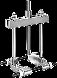
I used a bearing separator and puller...like this setup....Originally Posted by allenj20

heat up the pulley ( I used a map gas bottle from home depot) ....plus the help of a nice impact gun to turn the puller bolt
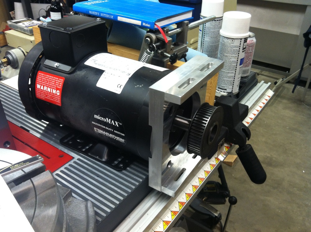
To re-install, I wrapped the rotor in aluminum (so the wife wouldn't know what it was) and put it in the freezer overnight. The next day I pulled out the rotor and heated up the pulley really good. It slipped right on