Need Help with some Gear Measurements


Results 1 to 10 of 10

Thread: Need Help with some Gear Measurements

  1. #1
    Registered
    Join Date
    Sep 2008
    Location
    USA
    Posts
    6
    Downloads
    0
    Uploads
    0

    Default Need Help with some Gear Measurements

    I am looking for someone who knows how to measure gears.

    I need this rack to be pulled down by these series of gears.

    Each system is the same in the picture I am providing but I need the gears of each system to be able to pull down separately the distance of 1 inch, 2 inches and 3 inches.

    Also if you can please provide the equations you used and any suggestions to make the system more efficient, thanks.

    Here's a link to the picture of the system:

    http://i6.photobucket.com/albums/y2...a/GearTrain.jpg

    The pole connecting to the Worm Gear will be connected to an arm that will be turning an arm connected to it 3/4 an inch in distance.

    Here's a picture of what I mean:

    http://i6.photobucket.com/albums/y2...kzelda/Pole.jpg

    I also would need calculations for the gear measurements to be able to bring that rack down those distances if the arm were only turned 1/2 an inch.

    The circle will be 6 inches in circumference for the arm that turns 3/4 an inch and 4 inches in circumference for the arm turning 1/2 inches.

    Also, please let me know if the circle needs to be bigger to compensate for the possible size of the gears.

    Similar Threads:


  2. #2
    Registered
    Join Date
    Aug 2005
    Location
    USA
    Posts
    1622
    Downloads
    0
    Uploads
    0

    Default

    Your pictures don't show up.


    The pictures could still explain your questions better.

    Moving a rack a certain distance can be roughly calculated with R(the gears pitch diameter/2)= length of stroke/1.5708 to get the arc length of say 90deg.

    Or stated another way,

    In your application as I read it. You have known lengths of strokes, but you need to select the nearest acceptable pitch diameter to develope a given rack stroke based on your degrees of rotation for an equivalent arc length. At the same time realize that there can be force gains and losses in the transfer.

    You can leave some adjustment in your arm length pivot point linkages to adjust for fine tuning or set stops on the rack to limit travel.

    See McMaster choices pg's 1039-1041

    DC


  3. #3
    Gold Member High Seas's Avatar
    Join Date
    Sep 2003
    Location
    Malaysia/Australia/NZ/USA
    Posts
    1113
    Downloads
    0
    Uploads
    0

    Default

    WELCOME ABOARD!
    Again - not seeing the pics I'll add that SDP/SI has a great deal of gear info in their component catalogs. (Catalog set is free and sooo good to have at hand - you might consider getting a copy.) Some of it may be on line too - good luck!
    Be nice to see the pics!

    Jim

    Last edited by High Seas; 09-15-2008 at 03:06 PM. Reason: close paren.
    Experience is the BEST Teacher. Is that why it usually arrives in a shower of sparks, flash of light, loud bang, a cloud of smoke, AND -- a BILL to pay? You usually get it -- just after you need it.


  4. #4
    Registered
    Join Date
    Sep 2008
    Location
    USA
    Posts
    6
    Downloads
    0
    Uploads
    0

    Default

    Ok, got some more gear measurements I need.

    I got a bevel gear pinion using the regular 90 degree angle tooth with a 0.208 pitch diameter and a diameter pitch of 48. This gear will be connected to a main bevel gear of 1.666 pitch diameter with the same diameter pitch of 48 with an 8:1 ration. The number of teeth doesn't matter. The length of the teeth also doesn't matter, but it has to make a right triangle or longer.

    With this information, what would be the easiest way to make this pinion set and what would be the other measurements like Whole Depth, Working Depth, Addendum, Deddendum, Pitch Circle, Pitch Cone Angle, Pitch Angle, Gear Thickness, Module, Center Distance, Tooth Thickness, Circular Pitch, etc?


  5. #5
    Registered Les A W Harris's Avatar
    Join Date
    Sep 2006
    Location
    USA
    Posts
    36
    Downloads
    0
    Uploads
    0

    Default Bevel gear data

    Kain,

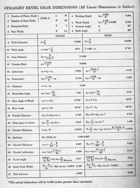
    8:1 reduction on bevels may be exceeding the possible, (see Machinery's Handbook) for the calculations.

    Minimum teeth in the pinion would be 13, with 31 min in the gear, so your 10 teeth pinion, 80 tooth gear, may not be possible, but go & run the numbers, the equations are all listed there to give your requested list of tooth data.

    With 48 Diametral Pitch, eg Whole Depth (ht = 2.188/P +0.002") would be 0.0476" for pinion and gear. However the Addendum's & Dedendum's are different for pinion & gear.

    The Center distance! Presume you mean Mounting distance, you will determine as you complete all of your basic 26 calculations.

    Cheers, Les.


  6. #6
    Registered
    Join Date
    Sep 2008
    Location
    USA
    Posts
    6
    Downloads
    0
    Uploads
    0

    Default

    Quote Originally Posted by Les A W Harris View Post
    Kain,

    8:1 reduction on bevels may be exceeding the possible, (see Machinery's Handbook) for the calculations.

    Minimum teeth in the pinion would be 13, with 31 min in the gear, so your 10 teeth pinion, 80 tooth gear, may not be possible, but go & run the numbers, the equations are all listed there to give your requested list of tooth data.

    With 48 Diametral Pitch, eg Whole Depth (ht = 2.188/P +0.002") would be 0.0476" for pinion and gear. However the Addendum's & Dedendum's are different for pinion & gear.

    The Center distance! Presume you mean Mounting distance, you will determine as you complete all of your basic 26 calculations.

    Cheers, Les.
    Is an 8:1 absolutely impossible? Because I got someone who claims they can do it. Might explain why they have been taking so long making this, lol.


  7. #7
    Registered Les A W Harris's Avatar
    Join Date
    Sep 2006
    Location
    USA
    Posts
    36
    Downloads
    0
    Uploads
    0

    Default Limitations

    Quote Originally Posted by Kain View Post
    Is an 8:1 absolutely impossible? Because I got someone who claims they can do it. Might explain why they have been taking so long making this, lol.
    The limit is the N.O.T. (number of teeth), in the pinion; the limits for the 20° system are 13/30 & higher, so if you want 8:1 it will have to be 13/104 teeth but at 48 DP your pitch dia's increase unless you go to 64 DP to stay close, (0.2031" X 1.6250" in that case, but will 64 DP be strong enough?

    Just checked my old notes, the 1949 standard shows ratio's 6.81 to infinity, setup table only go's to 6:1 but the equations look the same as in Machinery's Handbook.

    Cheers,


  8. #8
    Registered
    Join Date
    Sep 2008
    Location
    USA
    Posts
    6
    Downloads
    0
    Uploads
    0

    Default

    Quote Originally Posted by Les A W Harris View Post
    The limit is the N.O.T. (number of teeth), in the pinion; the limits for the 20° system are 13/30 & higher, so if you want 8:1 it will have to be 13/104 teeth but at 48 DP your pitch dia's increase unless you go to 64 DP to stay close, (0.2031" X 1.6250" in that case, but will 64 DP be strong enough?

    Just checked my old notes, the 1949 standard shows ratio's 6.81 to infinity, setup table only go's to 6:1 but the equations look the same as in Machinery's Handbook.

    Cheers,

    Actually everything else isn't as important as keeping that pitch diameter as small as possible while staying in the 8:1 ratio. So your saying raising that up to 64 would help?


  9. #9
    Registered
    Join Date
    Aug 2005
    Location
    USA
    Posts
    1622
    Downloads
    0
    Uploads
    0

    Default

    If strength was an issue, might a worm gear arrangment work for your application?

    DC


  10. #10
    Registered Les A W Harris's Avatar
    Join Date
    Sep 2006
    Location
    USA
    Posts
    36
    Downloads
    0
    Uploads
    0

    Default BEVEL GEAR CALCS

    Quote Originally Posted by Kain View Post
    Actually everything else isn't as important as keeping that pitch diameter as small as possible while staying in the 8:1 ratio. So your saying raising that up to 64 would help?

    Yes, as stated calculate for 13 X 104 teeth at 20° Pressure Angle at 64 Diametral Pitch.

    Here is a sample gear calc sheet!


    Cheers,


Tags for this Thread

Posting Permissions

  • You may not post new threads
  • You may not post replies
  • You may not post attachments
  • You may not edit your posts
  •  


About CNCzone.com

    We are the largest and most active discussion forum for manufacturing industry. The site is 100% free to join and use, so join today!

Follow us on


Our Brands

Need Help with some Gear Measurements

Need Help with some Gear Measurements