Large Brushed servo setup on the cheap (WIP) - Page 3


Page 3 of 18 FirstFirst 12345613 ... LastLast
Results 41 to 60 of 352

Thread: Large Brushed servo setup on the cheap (WIP)

  1. #41
    Member samco's Avatar
    Join Date
    Jul 2003
    Posts
    1754
    Downloads
    2
    Uploads
    0

    Default

    Sorry - I am not good at actually dressing up circuits. The gate resisters are 10ohm the resisters feeding the optos are aprox 270ohm. The pull up resisters on the back side of the optos are 10Kohm. The mosfet looking thing on the lower left is a 3 pin 15volt regulator. All the caps are .1uf except the one in parrellel with the boot strap cap which is 10uf.

    FDH44N50 N - MOSFET transistors 500V / 44A for the power mosfets.
    RURG5060 Ultra Fast Diodes 600V 50A for the free wheeling diodes
    IR2111 for the half bridge driver.
    MUR120RLGOSCT-ND DIODE ULTRA FAST 1A 200V AXIAL for the boot strap.
    LM340T-15-ND 15volt regulator
    TLP2530-ND PHOTOCOUPLER DUAL 6N135 8-DIP
    .1uf caps and
    iirc 10uf electrolytics.
    The big cap is 1900uf I think at 350volts (I think)

    Couple things
    - when there isnt any pwm signal applied to the bridge - both lower mosfets are on. (braking)
    - I had a lot of help from a emc developer that does high power circuits for his real job.
    - there is no current limiting yet.
    - you should find lower Rds mosfets.
    - if your going to run higher than 200v you need higer voltage boot strap diodes.
    - this cannot have 100% duty cycle pwm signal other wise the boots strap doesn't get charged.
    - use at your own risk (of cource)
    - great care was made to have a short power circuit loop - to help get rid of stray inductance.


  2. #42
    Member samco's Avatar
    Join Date
    Jul 2003
    Posts
    1754
    Downloads
    2
    Uploads
    0

    Default

    This is the little servo I have been playing with to teach myself a bit more tuning.
    http://www.electronicsam.com/images/...rt/ampmess.JPG

    Here is a picture of the following error just goofing around.
    http://www.electronicsam.com/images/...art/ferror.png
    This would work great for a mini/micro mill - Tempted to buy one for home.

    Now I finally got a decent read on the large servos votage/rpm=.125
    So at 150v = 1200rpm <- which is its maximum rating. That would give us a max speed of 200ipm with 2:1 and 3tpi.. (we where going to direct drive it but for ease of retro we are going to belt drive it.) Plus the 150v falls right into the operating range of the diy h-bridge.

    sam


  3. #43
    Gold Member acondit's Avatar
    Join Date
    Apr 2005
    Location
    USA
    Posts
    1778
    Downloads
    0
    Uploads
    0

    Default

    Sam,

    I am thinking about trying out some servos. I have some 63v 15amp peak servos. Do you think that your boards would be a reasonable match?
    I also have some smaller 100 watt servos 30 to 36v (I think). Would these work with your board design?

    Are you working on the design more (ie, current limiting)?

    Alan


  4. #44
    Member samco's Avatar
    Join Date
    Jul 2003
    Posts
    1754
    Downloads
    2
    Uploads
    0

    Default

    The drive 'should' be able to handle 20a continuous at around 150v and close to 40a peak.. But I have only tested it so far at 10a at around 60v.

    Remember - no current limiting yet. I was planning on using some fast blow fuses to try to save the mosfets in case of an oops.. I don't know how well in practice this will be.

    sam


  5. #45
    Banned
    Join Date
    Sep 2005
    Location
    Sweden
    Posts
    229
    Downloads
    0
    Uploads
    0

    Default

    You could perhaps add something like this + a comparator and a little logic to shut down the output when it draws to much current!?


  6. #46
    Member samco's Avatar
    Join Date
    Jul 2003
    Posts
    1754
    Downloads
    2
    Uploads
    0

    Default

    I am a bit leary about adding current limit yet as the guy who helped be design the low inductance current loop of the h-bridge said there are right ways and wrong ways to add current limit. He suggested a aprox $30 magic chip that you would hook in series with the motor that would be used as the current sense circuit. Not messing up the h-bridge by adding a series resister high wattage resister.

    But I have not had much time to look into that.

    sam


  7. #47
    Member
    Join Date
    May 2006
    Location
    Australia
    Posts
    2420
    Downloads
    0
    Uploads
    0

    Default

    Hey Sam, have you looked into/heard of high side current sensing as opposed to using sense resistors in series with the motor (Low side)? I cannot say I really know what is involved, but I wonder if it involves measuring the Vce Sat voltage of the output FET's.

    EDIT :

    I did a quick Google and found this :

    http://www.national.com/nationaledge/

    Don't know if something like this would work, not enough hours in the day to find out right now .

    Russell.


  8. #48
    Registered
    Join Date
    Jun 2007
    Location
    France
    Posts
    6
    Downloads
    0
    Uploads
    0

    Red face

    hello,
    I am a new user of emc.
    I bought a pluto-p card.
    Do you have a schematic of the mosfet board ?
    I learn electronics for this project !

    PS : Excuse my poor english, but i'm french guy...


  9. #49
    Gold Member acondit's Avatar
    Join Date
    Apr 2005
    Location
    USA
    Posts
    1778
    Downloads
    0
    Uploads
    0

    Default

    Russell, Sam,

    Is there a reason why all of the FETs and Diodes that require heat sinks can't be on one side of the board so that you could use a common heat sink?

    Alan


  10. #50
    Member samco's Avatar
    Join Date
    Jul 2003
    Posts
    1754
    Downloads
    2
    Uploads
    0

    Default

    like this?

    http://www.electronicsam.com/images/...t/mounting.JPG

    that is how I have it setup right now.


  11. #51
    Gold Member acondit's Avatar
    Join Date
    Apr 2005
    Location
    USA
    Posts
    1778
    Downloads
    0
    Uploads
    0

    Default

    Sam,

    What exactly is the "bootstrap"?

    Alan


  12. #52
    Gold Member acondit's Avatar
    Join Date
    Apr 2005
    Location
    USA
    Posts
    1778
    Downloads
    0
    Uploads
    0

    Default

    Sam,

    I posted this on Epineh's thread and got no response. So since you worked with JMK on this design I hope you can answer the question.

    What is the purpose of the large capacitor (1900uf 350V) across the high voltage supply? Is it just a smoothing filter? Or is it required for charge storage because of the rapid PWM pulse rate? Or both?

    Is the capacitor required for a lower voltage and amperage?

    How would one size the capacitor (if required) for say 60 volts and 20 amp peak?

    Thanks,
    Alan


  13. #53
    Member samco's Avatar
    Join Date
    Jul 2003
    Posts
    1754
    Downloads
    2
    Uploads
    0

    Default

    The size was picked - because I have a bunch of them

    It is for getting rid of stray inducatance and making the inductance of the h-bridge very low.

    I don't know how you would calculate what it should be though - my electronics is a bit rusty. I think you want to use one as big as you can get away with - which will be easyer for you as your running a lower voltage.

    sam


  14. #54
    Gold Member acondit's Avatar
    Join Date
    Apr 2005
    Location
    USA
    Posts
    1778
    Downloads
    0
    Uploads
    0

    Default

    Sam,

    I was looking at the UHU servo board designs. It has a simple current limiting scheme that seems like it could be easily adapted to your basic design. My problem is that I may be missing lots of details.

    Do you have any objection to my posting a modified schematic for comment on the general electronics forum?

    Alan


  15. #55
    Member samco's Avatar
    Join Date
    Jul 2003
    Posts
    1754
    Downloads
    2
    Uploads
    0

    Default

    Anything that can be done to improve the circuit - I am all for..

    Go for it. I have been too busy to do anything right now.

    thanks
    sam


  16. #56
    Member samco's Avatar
    Join Date
    Jul 2003
    Posts
    1754
    Downloads
    2
    Uploads
    0

    Default

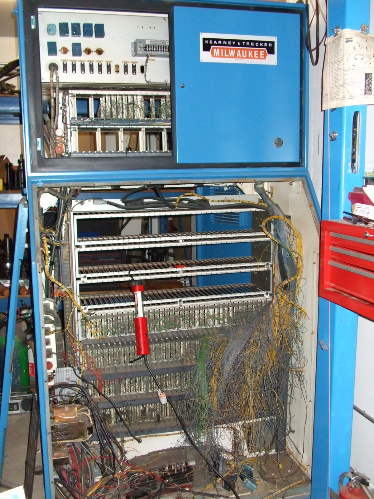
    no turning back now..


  17. #57
    Member
    Join Date
    Jun 2003
    Location
    Boalsburg PA
    Posts
    866
    Downloads
    0
    Uploads
    0

    Default

    that's going to be a lot of space for electronics


  18. #58
    Member samco's Avatar
    Join Date
    Jul 2003
    Posts
    1754
    Downloads
    2
    Uploads
    0

    Default

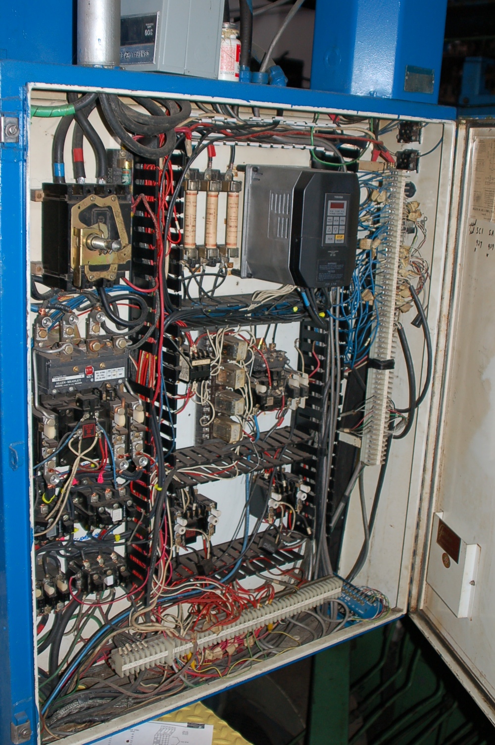
    That control cabinate is going. Most everything is going in here. A lot of the 'stuff' in the box will not be needed.

    sam


    Quote Originally Posted by unterhaus View Post
    that's going to be a lot of space for electronics


  19. #59
    Registered
    Join Date
    Oct 2006
    Location
    USA
    Posts
    83
    Downloads
    0
    Uploads
    0

    Default Converting a Kasuga to EMC2 - need pwm explained

    Samco,

    I've been following your progress - way to go.
    I am converting a Kasuga knee mill (http://www.foxpointdesign.com/cnc%20stuff/IMG_1149.jpg) from Bandit to EMC2. I have the Mesa 5I20 that I am just getting set up to play with using smaller test servos and the 7I40 servo amps. I was wondering how you connect the pwm signals to your H bridge. Do you connect a CW pulse stream on one side of the bridge and a CCW pulse stream on the other? Is that all there is to it??? Just wondering how this works...
    Thanks!
    Tom


  20. #60
    Member samco's Avatar
    Join Date
    Jul 2003
    Posts
    1754
    Downloads
    2
    Uploads
    0

    Default

    Yes - The servo amps I have been playing with require a PWM signal for CW and a pwm signal for CCW (I call it PWM+PWM). (very simple H-bridge.) Now IIRC - the mesa card only supports PWM+DIR at the moment. Well - unless you buy the servo interface card which gives you +/-10v out. (7i33). SO if you want to do PWM+PWM - you will need a little bit of logic.

    most industrial amps use +/- 10v or pwm+dir.

    sam


Page 3 of 18 FirstFirst 12345613 ... LastLast

Tags for this Thread

Posting Permissions

  • You may not post new threads
  • You may not post replies
  • You may not post attachments
  • You may not edit your posts
  •  


About CNCzone.com

    We are the largest and most active discussion forum for manufacturing industry. The site is 100% free to join and use, so join today!

Follow us on


Our Brands

Large Brushed servo setup on the cheap (WIP)

Large Brushed servo setup on the cheap (WIP)