Reply with Quote
Not yet but I only have to make pistons, rods, and rings. Everything else is made.


Did you get it running?
Not yet but I only have to make pistons, rods, and rings. Everything else is made.
Just to let everybody know, the rights to the plans for the demon V8 now belong to Executive Model Design. They purchased the rights to sell plans to those who wish to build one but to also look into producing mechanics kits for those who would like to purchase the parts and assemble it themselves.
The pricing will remain the same for electronic copy's of the plans but an added cost will be in place for those who want printed copies. The added cost will cover ink, paper, and postage. The plans should be available soon on there website.
I will pass off my list to them of the people who have purchased the plans from me so replacement can be made in the event of a computer crash. Anybody who wishes to purchase plans from now forward can get them at Executive Model Design.
This is an awesome project. Excellent craftsmanship. I definitely want to keep my eye on this one.
Hi Steve
Glad to see you are at it again. Looks just like it could be a full-size car.
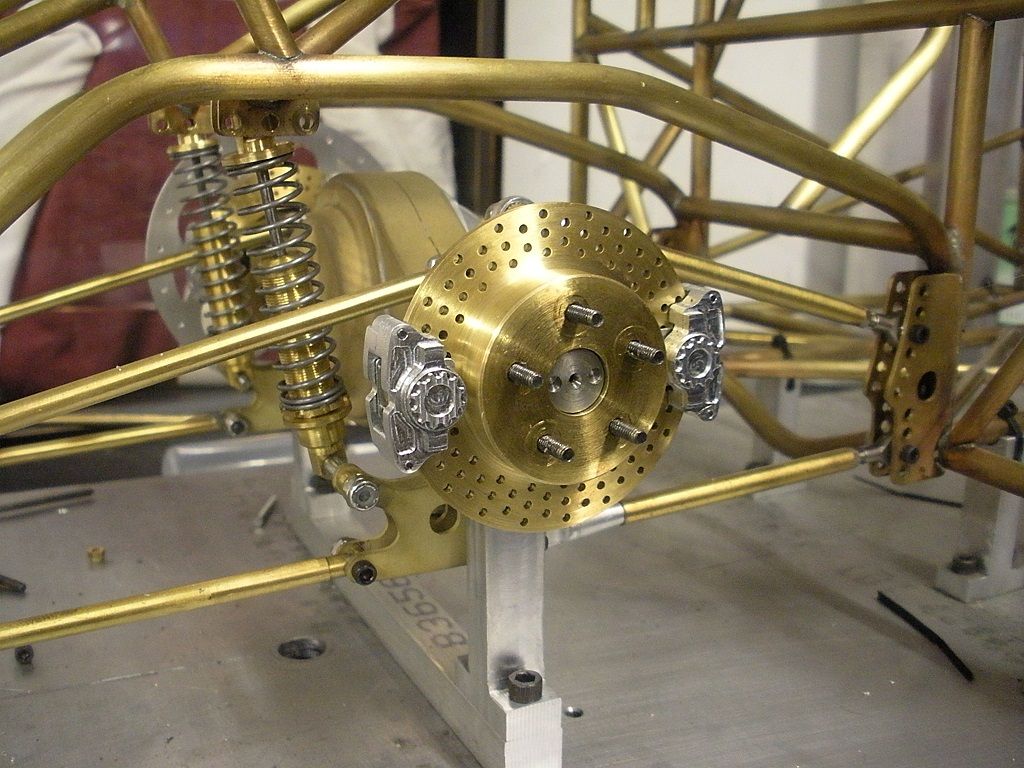
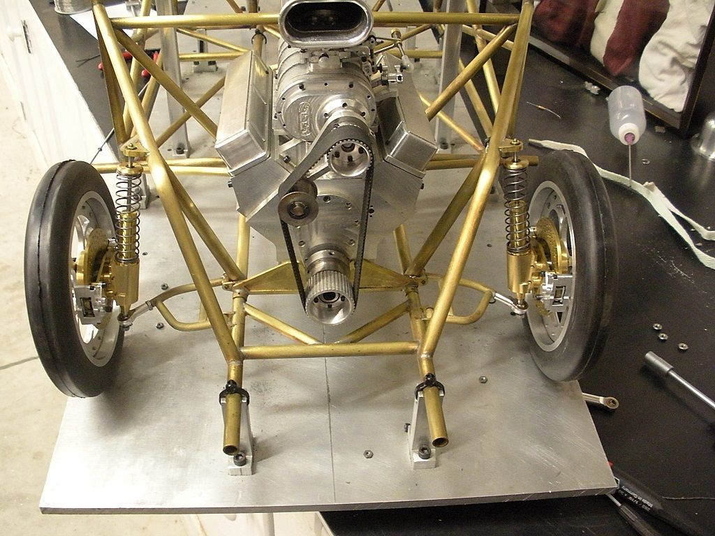
Are those parts brass, or is it just the lighting?
Red to red and black to black, or it's ashes to ashes and dust to dust.
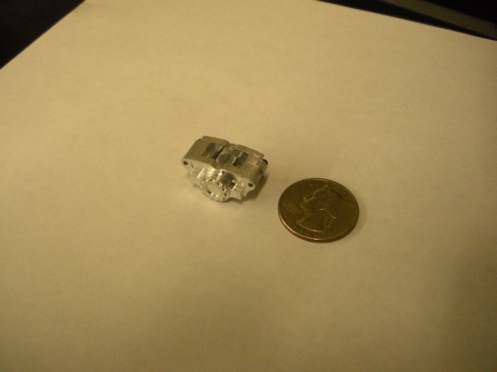
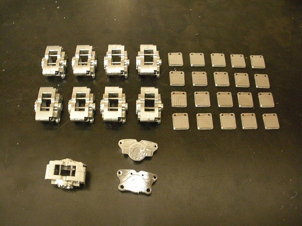
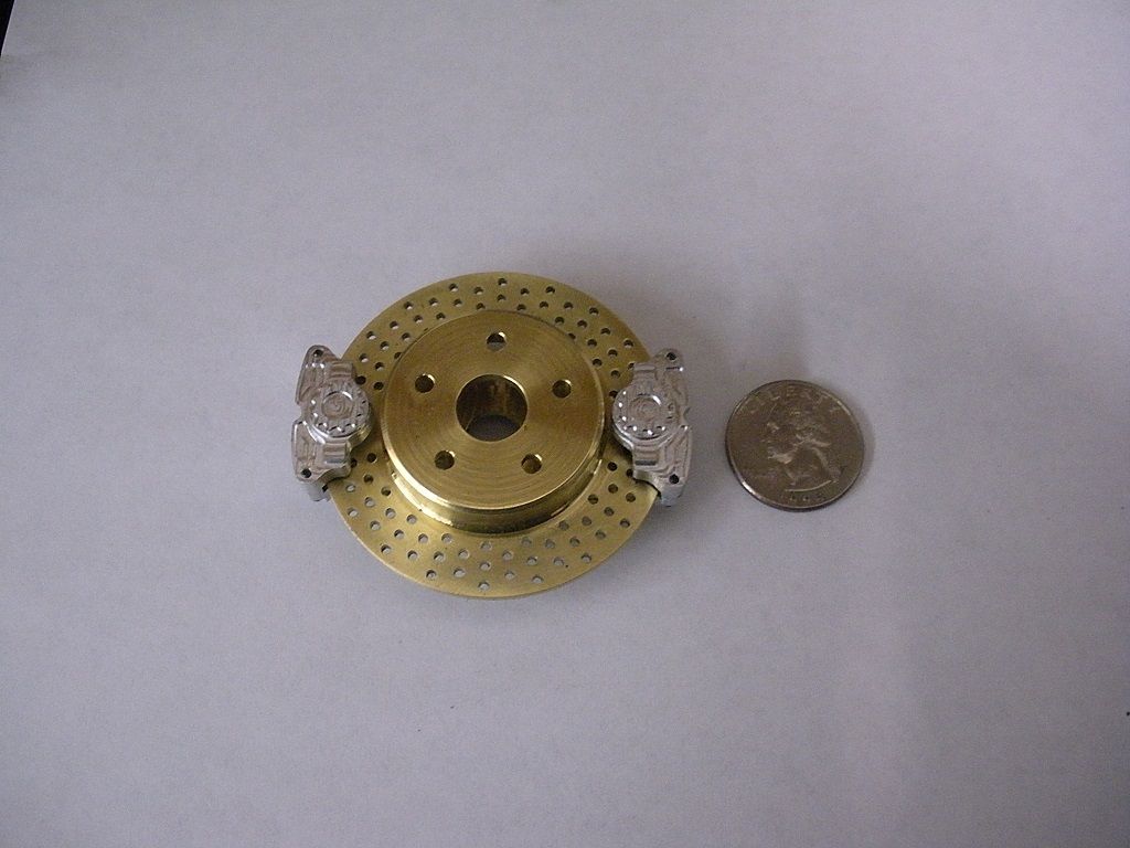
Calipers are aluminum. The rotors are brass
Nice work, here is One I always thought would make a real nice Model Engine the Australian Repco Brabham F1 Engine from the mid Sixties, Very sweet looking engine and considering the Full size one was based on an Oldsmobile Alloy pushrod V8 from the early Sixties and converted to a OHC F1 motor that won a few World Championships with Machinery and techniques used in the real world that are more akin to what a Manual machinist would use a CNC built one would be a good project for a Model.
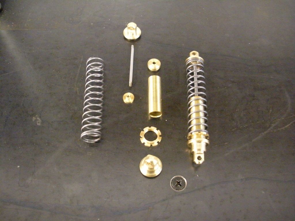
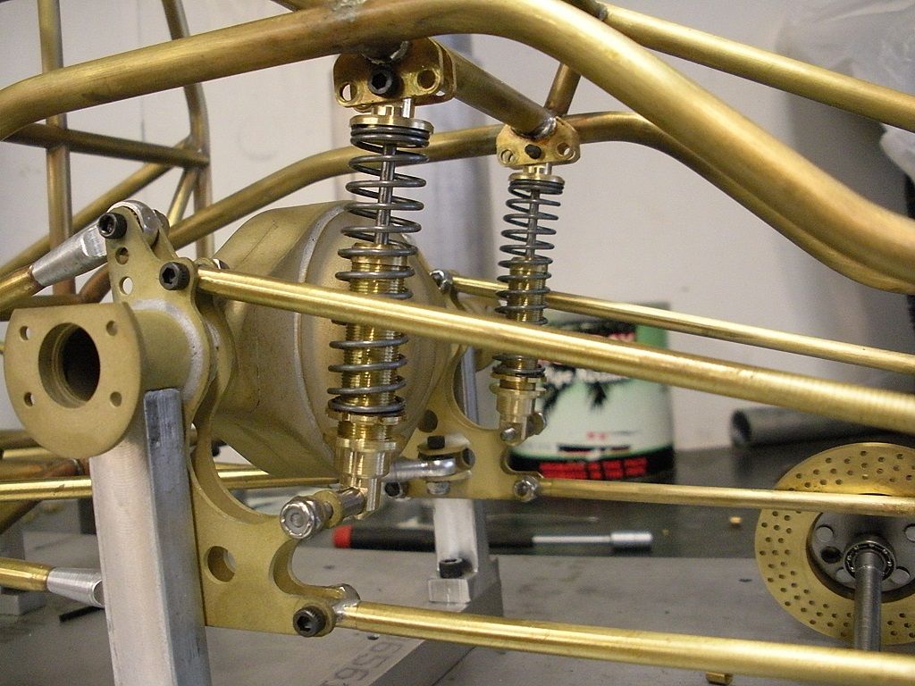
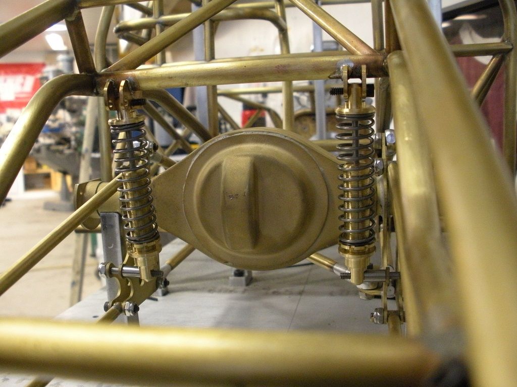
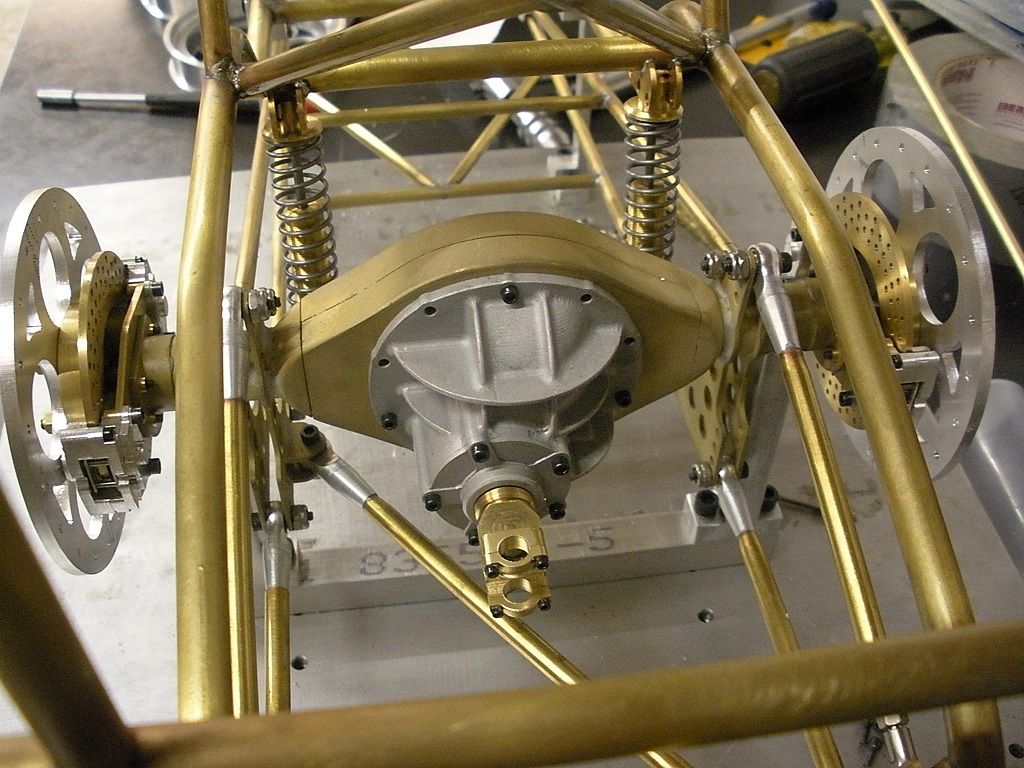
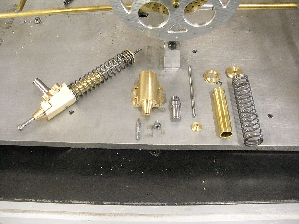
Well i found myself with a day off from work so i made a pair of rear shocks. They are basically just like an RC shock except all brass instead of plastic. I couldn't find springs close enough to size so I wound a pair to the OD and length I needed. They were assembled and soldered together. I modeled them after the adjustable coil over drag racing shocks.
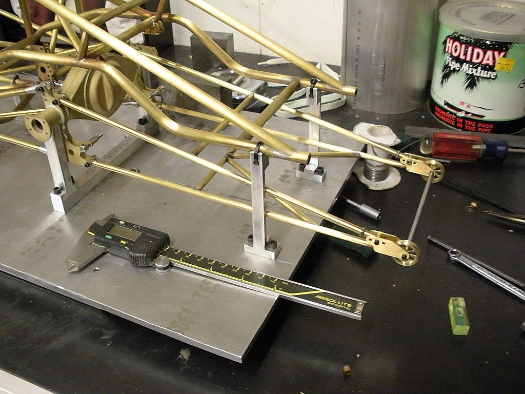
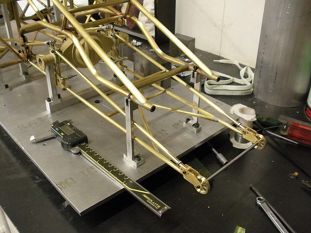
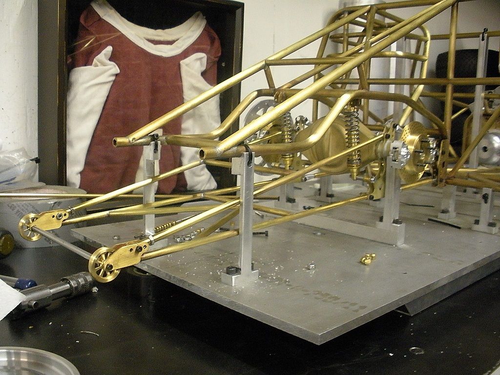
Finally had a chance to get something done. Made the wheelie bars They are an exact copy of some bars i found on the web.
- - - Updated - - -
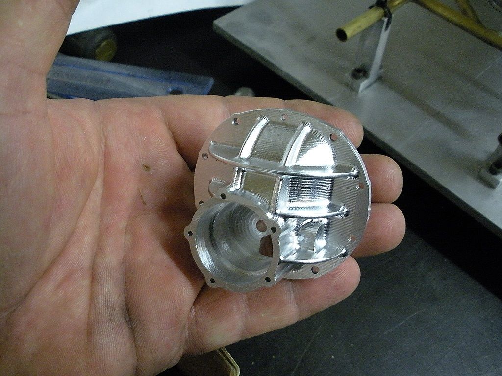
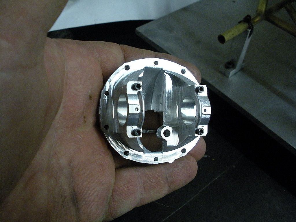
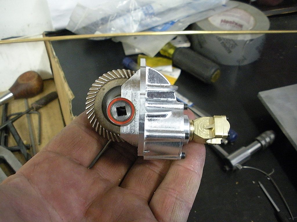
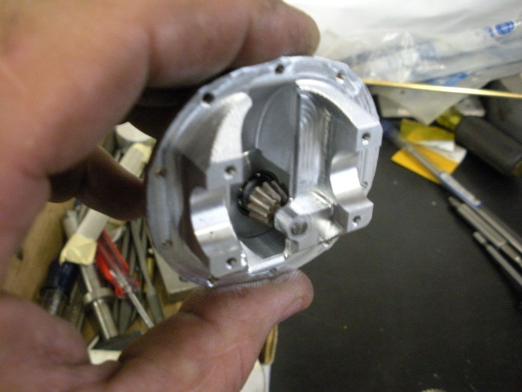
Center section is almost complete. I still need to drill and tap the drain hole for the gear lube and make a drain plug. If I can get the gear cutting nailed down I might be able to make a ring and pinion set.
Amazing! I missed a lot of this update.
Awesome detail, as always, Steve.
Will the suspension dampers work by squeezing air through small holes? I ask that because I assume oil will leak out unless you have O-ring seals.
Red to red and black to black, or it's ashes to ashes and dust to dust.
No holes. Air has to pass around the piston.
A little update on the car.
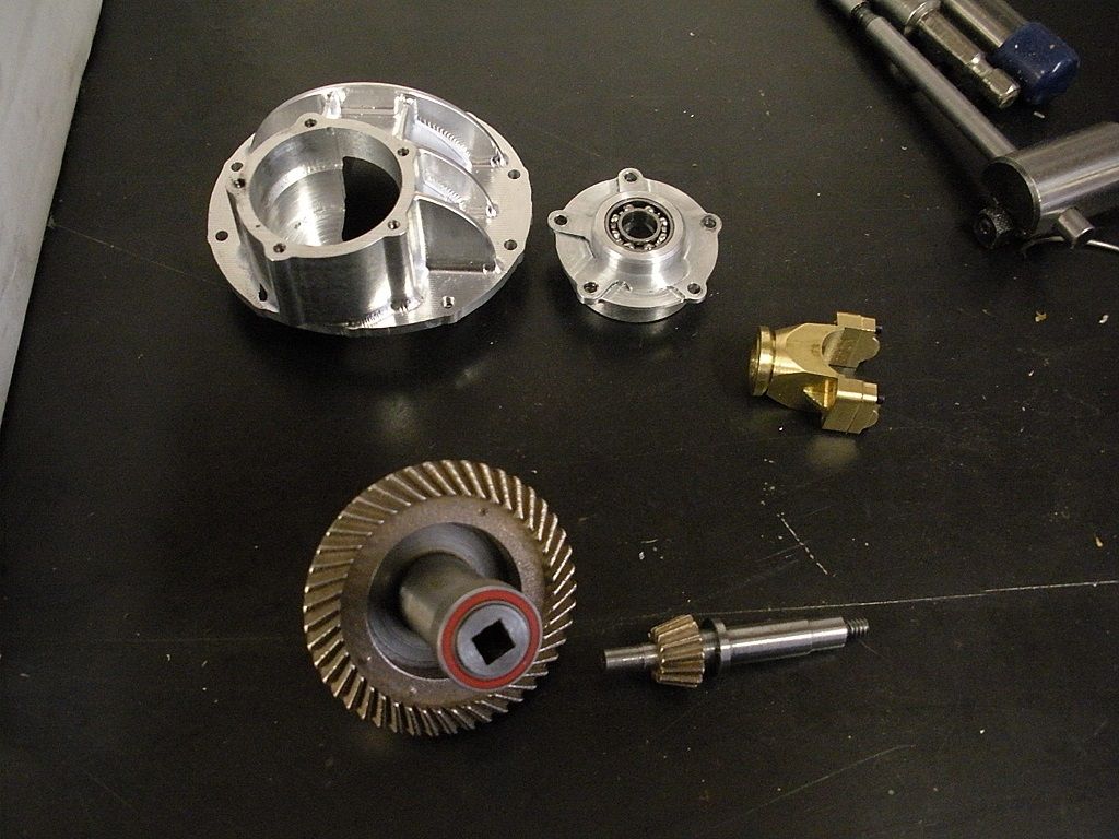
I couldn't make heads or tails of the gears as far as the exact placements of the cuts with the custom cutters. I fully understand the article and what is supposed to happen but the numbers didn't seem to work so i freakin winded it. I patched as much of the article together with the 3D cad and drew up the gears and eyeballed the shape of the teeth and did my own thing. After a few hours of adding a little here and taking off a little there I had a set of gears that were ready to "test". My pal was going to print the gears in ABS and pass them off to me to try. Couple days before I was ready his printer died. I really needed them printed on a "good" printer with good resolution. So I searched the web and found a place that could print ABS. Come to find out the set in ABS on a really good printer costs about 75 bucks plus shipping. After further snooping on the website i found they could 3D print in steel so I had to see what that would cost. 42 bucks in steel plus shipping so guess what I did. Well they are not that bad other than a bit of a rough finish but I figure I could run them in with a little diamond paste. They don't take kindly to drilling and threading. My mounting holes were printed into the part .005 under and I had to drill to size. Drill bit got hot real fast but it worked. Tap is still pissed at me but it did take a thread. Obviously not as nice as machined gears but cheap in my opinion. I still have an interference issue that I think some button head screws will clear up but other than that everything fit as planned.
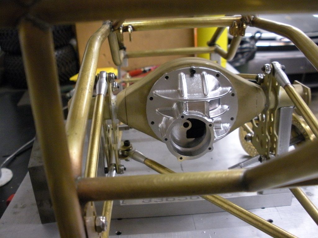
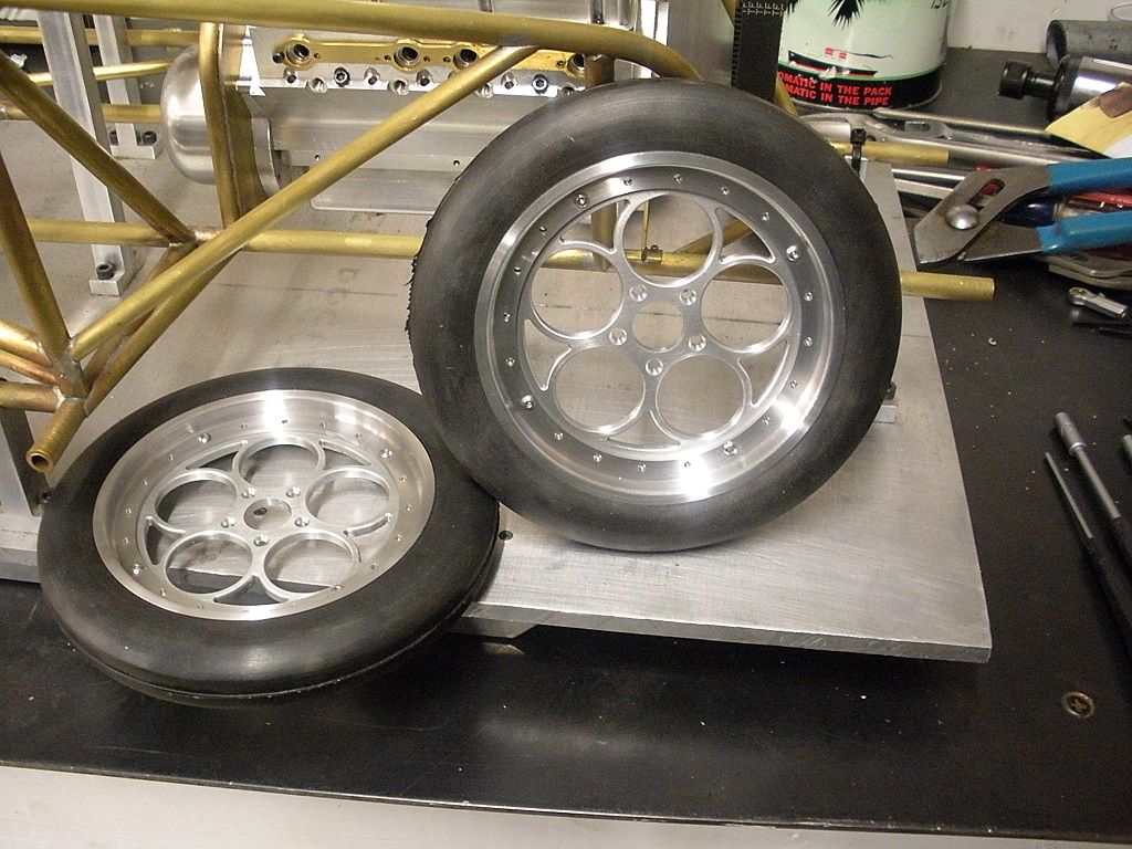
Put the final touches on the rear end. The center section was completed by cutting a clearance on the bottom so the mounting hardware could be inserted through the holes. The oil fill plug was drilled and tapped. The yoke was cross drilled so the Ujoint can be mounted. The entire thing was assembled complete for the first time. I also had a chance to make the front rims and the centers for the rear rims. I have 100 stainless screws on the way to assemble them.
What! No valve stems?
Excellent work. I would not have thought of using sintered gears. I am only guessing that is the process they use when printing steel.
Do you have a link to that source?
May come in real handy at some point.
It is coming together nicely. Work of art.
Lee
https://i.materialise.com/
I think they are in belgium.
Another weeks worth!
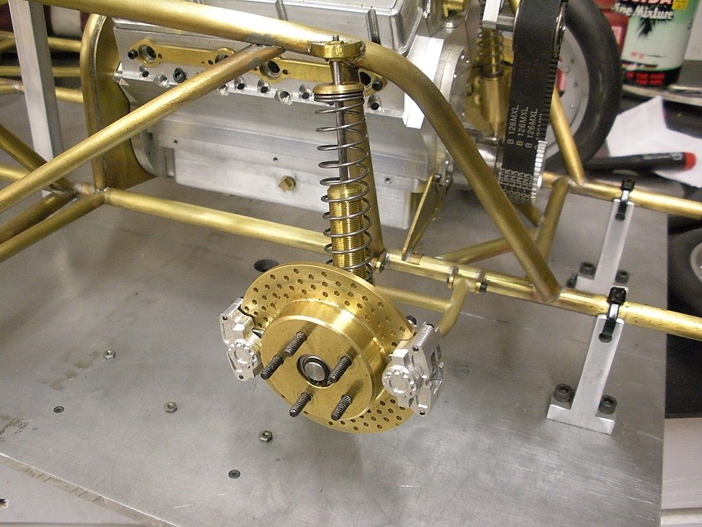
I have finished the front struts. I still need to make the mounts for the top so stay tuned on that. Started on the pieces Saturday so there is 5 days, a couple hours a day. Need to sort out the top mount and make the hub so I can get the front wheels mounted.
Well I finally have wheels on the front. I finished up the heim joints on the A arms and made the hubs. The brakes are bolted on for the first time and the tire is mounted. I am going to make a wheel spacer tomorrow to give a little more room between the rim and calipers.
Well gentlemen, here's where I'm at on the little Chevy. The show is this weekend in Zanesville Ohio. If you can get there here is what you will see. I ran out of time and could not finish the rear wheels. I still need to make the bead locks.