Build Thread Conversion Tutorial for DC-K40 / TB6560 (blue board from Ebay) for Non-professionals


Page 1 of 2 12 LastLast
Results 1 to 20 of 21

Thread: Conversion Tutorial for DC-K40 / TB6560 (blue board from Ebay) for Non-professionals

  1. #1
    Registered
    Join Date
    Sep 2011
    Location
    Brasil
    Posts
    29
    Downloads
    0
    Uploads
    0

    Talking Conversion Tutorial for DC-K40 / TB6560 (blue board from Ebay) for Non-professionals

    Hello everybody,
    After 6 months studying, learning, having help from friends and researching I finally successfully converted my Chinese DC-K40 machine to a TB6560 “blue board” to make it cut vectors with mach3.
    That Moshi driver/Moshidraw did not work well, and do not cut vector files from ACad CorelDraw.
    I first would like to say that I am a non-professional, but I understand a little about electronics, solder wires and mach3 software (this is the most difficult part)
    This is a small thread showing all the steps I did to convert my machine. Like I´ve said: I AM NOT A PROFESSIONAL, and I`M NOT EARNING ANY $$$$ FOR THIS.
    As a non-professional I´ll use a simple language to explain all the steps.
    This is my machine´s conversion, and using a generic TB6560 board that I´ve bought from Ebay. Remember that your machine inner setup and board can be different from mine.
    All hints from expert guys to improve other´s conversions would be welcome for this thread.
    I´d like to apologize for my poor English, but I´ll do my best to show as much as pictures as necessary from the mach3 software setup and shots from my machine.
    Some advises are import since it is a laser machine:
    1-Always use laser goggles when the laser is working.
    2-Always use laser goggles when the laser is working.
    3-Always use laser goggles when the laser is working.
    4-Always use laser goggles when the laser is working.
    5-….
    6-This is not a toy
    7-Did you get it?

    First of all you have to understand the basic: the TB6560 “blue board” is not a controller, it is a just a driver controlled by mach3 software. Mach3 software is the brain of all. The TB6560 board will be just a driver that will get all the information from mach3 and send to the stepper motors, and will receive information from the machine´s limit/home switches to send to the mach3. Period.
    (I´m explaining it because I first thought that the TB6560 board was the controller, and I´m sure that most of the non-professional people thought same way)

    I recommend a good read on mach 3´s manual since it will be the machine’s controller. G-Code (the code that mach3 use to do all the work) is not difficult to understand, but you have to spend some time studying like I did.
    I will not explain mach3 to anyone. I will just show the setup page pictures.

    Just for information; you will not need to change any wire that goes to the front panel; this panel will work as was working before the conversion. There we have a laser on/off pushbutton, a laser fire test button and a potentiometer that increases the laser power to cut a vast array of materials and thickness.

    Remember: the TB6560 board will not control the laser fire; MACH3 will do that through the 25 pin serial port. Although the wires to control the laser fire will be soldered in the TB6560 board, it will just be a simple way to get the input from the 25 pin serial port.
    You will see that I use the relay to turn on/off the laser (only in the beginning and ending of a work), it is just a safe procedure, and the relay do not control the laser trigger while the work is in progress. In the next lines you´ll see how it works.

    Similar Threads:


  2. #2
    Registered
    Join Date
    Sep 2011
    Location
    Brasil
    Posts
    29
    Downloads
    0
    Uploads
    0

    Default

    So, lets start…


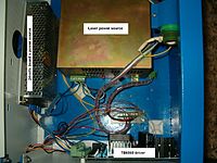
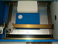
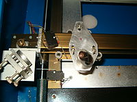
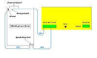
    This is the picture of my laser machine arrangement:


    Some machine´s arrangement are different from mine. If your machine is different from mine you will need some patience.

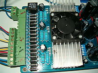
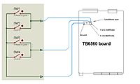
    To make the DC-K40 work properly with a Tb6560 board we have to setup 4 stuff on the hardware: power up the TB6560 board with 24 volts, stepper motors, limit/home switches, and finally the laser trigger.


  3. #3
    Registered
    Join Date
    Sep 2011
    Location
    Brasil
    Posts
    29
    Downloads
    0
    Uploads
    0

    Default Powering the TB6560 Board

    Powering the TB6560 board.
    Take a look at the shot below:


    Simple to do that, right? 24 volts from power source.
    This “blue board” can bear up to 36 volts…


  4. #4
    Registered
    Join Date
    Sep 2011
    Location
    Brasil
    Posts
    29
    Downloads
    0
    Uploads
    0

    Default The Stepper motors

    The stepper motors setup.
    I´m not sure, but I guess my both stepper motors are Nema 17.
    In a laser machine we don´t need strong motors since we don´t have a spindle that touch the piece that will be cut.
    Take a look at the picture again:


    Pay attention to the Axi´s wire setup and see that the wire sequence for X axis is different from Y axis sequence.
    X axis sequence: Blue, Red, Yellow, White
    Y axis sequence: Yellow, White, Blue, Red

    You´ll need to extend the X axis wires because It too short to reach the board. To do that you´ll need around 20 inches long wires and a soldering iron.

    On the picture above you´ll also see the dip micro switches setup for my Nema motors .
    This is the setup I´m using.
    -Current setting:
    1-off
    2-off
    I have 25% of current to my motors

    -Decay mode
    3-on
    4-on
    I have FAST option to my motors

    -Micro Step
    5-off
    6-on
    1/16 microstep


    On Mach 3…

    …select config/ports and pins/motor outputs…
    The picture below shows the pin/ports setup of my TB6560 driver. I followed the manual that came with my board. Yours can be different. I recommend to follow your board´s manual to setup the stepper motors ports and pins for X/Y axis.


    Go to config/motor tuning:


    These are the setup for steps/speed/acceleration for my X/Y axis Nema motors.

    Ignore the Z axis setup for awhile, it will be explained in the laser fire.


  5. #5
    Registered
    Join Date
    Sep 2011
    Location
    Brasil
    Posts
    29
    Downloads
    0
    Uploads
    0

    Default Home/Limits

    Limit/home switches
    You´ll need to buy 4 mechanical limit/home switches, because the machine´s limits are optical (I don´t think it work with the TB6560 blue board) and there are only 2 of it in the machine (only home switches, go figure why…)
    The pictures bellow shows where I glued the 4 limit/home switches (I glued it with industrial silicon). You have thousands ways to install these switches.


    My switches are “open circuit” models, and when they are activated it “short the circuit”.
    This the setup I´m using in my machine:


    On mach3 go to config/ports and pins/input signals, see the setup in the picture below:


    In the same picture you see the option “Automated Setup of Inputs”. Click on it and select the switch/axis you want to setup. Read the Mach3´s user manual and you´ll see how to setup limit/home switches using this option.


  6. #6
    Registered
    Join Date
    Sep 2011
    Location
    Brasil
    Posts
    29
    Downloads
    0
    Uploads
    0

    Default Laser trigger

    Laser Setup:
    *Don´t forget the goggles!

    To fire the laser you´ll need to send from 3,3 to 5,0 volts to the laser power unit TH input. Where can I get these voltage??? From the 25 pin serial port.
    I´m using the Mach3 Z axis action to send me this voltage. My computer works with 3,3volts, but the laser power source that came with my laser machine can work from 3,3 to 5,0 volts.
    The picture bellow shows the way I get the signal from pin4 and ground of the 25 pin serial cable:


    Setup dir pin4 in mach3 config/ports and pins/motors output


    The Z setup above was the only one that worked, and it took some sleeping nights to find it out.

    I had one problem: the dir pin4 was always sending 3,3 volts when the laser machine was stopped (before or after a project). If it is sending 3,3volts means that the laser is firing. The way I found to solve this problem was to use the spindle relay.
    This is the wire setup from board to Laser PSU:


    Go to config/ports and pins/output signals and setup like the picture below:


    To make the relay active go to config/ports and pins/spindle setup, and follow the picture bellow:


    On config/motor tuning you´ll need to set the maximum speed and acceleration for the Z axis, this way the laser will have the minimum delay.


    There is a command to control the laser fire on mach 3 (using M10Px, M11Px) but it is a kind of complex and I prefer to use the Z axis to control it.

    Don´t forget to use your goggles and turn on the water pump before turn on the laser.

    If the laser do not work, check:
    The config setup on your TB6560 users manual. Enable all pins and ports exactly like in the user´s manual.
    The laser Switch push-button and the potentiometer on the machine´s main panel.


    To convert the files from DXF to G-code files I´m using LazyCam software.

    This is how I converted my Cheap Chinese CO2 laser machine.
    If anyone have something to help improve this conversion it will be welcome.
    Thank you
    Raphael


  7. #7
    Registered
    Join Date
    Sep 2011
    Location
    Brasil
    Posts
    29
    Downloads
    0
    Uploads
    0

    Default This the machine working...

    http://www.youtube.com/watch?v=N6EHbkGb5lU]Cheap co2 laser machine + Mach3 + Cheap Ebay TB6560 board - YouTube

    It was still without the limit/home switches and a laser big delay. Now I installed the switches and the delay is gone (by increasing the Z axis speed/acceleration)


  8. #8
    Registered
    Join Date
    Mar 2012
    Location
    USA
    Posts
    2
    Downloads
    0
    Uploads
    0

    Thumbs up

    I'm curious if you got the original board to work with the pc? I just recently bought a K40IV and just cant get the machine to get recognised by the PC, keeps saying unknown USB device. I have emailed the seller numerous times and they keep suggesting changing the USB ports which didn't help. I got fed up eventually and bought the DSP board from LightObject. Excellent post tho


  9. #9
    Registered
    Join Date
    Sep 2011
    Location
    Brasil
    Posts
    29
    Downloads
    0
    Uploads
    0

    Default

    Quote Originally Posted by 5by5laser View Post
    I'm curious if you got the original board to work with the pc? I just recently bought a K40IV and just cant get the machine to get recognised by the PC, keeps saying unknown USB device. I have emailed the seller numerous times and they keep suggesting changing the USB ports which didn't help. I got fed up eventually and bought the DSP board from LightObject. Excellent post tho
    Yes I did. But I can´t say it worked because it didn´t do anything I wanted (cut vectors, read vectors file and so). I learned how to draw in CorelDraw and than import to Moshi, but the cut was terrible.
    Chinese people do lots of stuff, I don´t understand why they don´t make a simple software to read and cut DXF files, instead that moshidraw; I´m 100% sure that they would sell twice more machine than they sell with moshidraw.


  10. #10
    Registered
    Join Date
    Mar 2012
    Location
    USA
    Posts
    2
    Downloads
    0
    Uploads
    0

    Default

    I know what you mean, I was telling my wife last night that Moshidraw software was up to version 9.90 and still they refuse to hire an english speaking person to do the translation after at least 9 versions. I was able to get the laser to talk to the pc by trying it on windows xp instead of 7 (which should work). The cuts were pretty bad, but hey atleast I know that all the parts are working as they should.


  11. #11
    Registered
    Join Date
    Jun 2012
    Location
    Germany
    Posts
    1
    Downloads
    0
    Uploads
    0

    Default

    Nice! I also bought exactly this TB6560.

    BUT My DC-K40iii (what ever that means) has a MoshiBoard 4.1. The 2 optical and one y-Motor are combined in one flat cable. And of course i want to use the optical swithes with the TB6560 board.

    Also I read some other posts that the TB6560 needs some modifications to be a good board ... I have the 3 axis version as you do.


  12. #12
    Registered
    Join Date
    Nov 2012
    Location
    uk
    Posts
    2
    Downloads
    0
    Uploads
    0

    Default Problem

    Hi guys. I have the same machine and the same components. I have a request, I need help with connected TB6560 with power supply (what the above post). I'm interested in the exact cable connection Relay 5V (MIN, GND, MOUT) with the power supply. Looking at the above post that I can not read where cable was going. THX


  13. #13
    Registered
    Join Date
    Apr 2012
    Location
    uk
    Posts
    21
    Downloads
    0
    Uploads
    0

    Default Differant Laser Supply ??

    Hi there, great tutorial but I have a question or three

    Your Laser Supply is different to the one in my Dc K40 and I was wondering if you could help.


    Here's a couple of pictures of the connections.


    The Test fire button and the wires going to the original moshiboard are connections to "L" and "G" on the middle connector. "L" is 5v & "G" is ground.
    As you can see I have no connection marked as "TH".

    So I guess my question is, is "L" the same as "TH" on yours?

    Any help would be appreciated, I have set it to fire using the relay on the tb6560, but as we all know, that's not really the way to go.

    Thanks

    Last edited by p00ky; 01-16-2013 at 08:14 PM. Reason: Pics grrr


  14. #14
    Registered
    Join Date
    Apr 2012
    Location
    uk
    Posts
    21
    Downloads
    0
    Uploads
    0

    Default

    SORTED

    After some advice from machsupport, a user named Tweakie.CNC all's well. The "L" connection seems to be the TTL line. So if you have my power supply, now you know.


  15. #15
    Registered
    Join Date
    Mar 2013
    Location
    Spain
    Posts
    1
    Downloads
    0
    Uploads
    0

    Default

    Since Mach 3 can actually have active high or active low inputs, why use mechanical limit switches instead of the built in optical ones? (planning to change their position so they act as both home and limit switches)


  16. #16
    Registered
    Join Date
    Aug 2008
    Location
    US
    Posts
    60
    Downloads
    0
    Uploads
    0

    Default

    old thread but the new moshidraw 2013 seems to work allot better then old, and even has vector file importing ie DXF,AI etc. also the link to corel function is more redefined from what im reading.
    a neighbor of mine has the 40w lser he just purchased from ebay the newer version he gave me a demo of it with new moshidraw and used corel as well, seems he had no issues at all. i believe he was running 32bit windows 7, maybe it will shed light for new people who want a laser on a budget, like myself.


  17. #17
    Registered
    Join Date
    May 2013
    Location
    Uk
    Posts
    3
    Downloads
    0
    Uploads
    0

    Default

    Hi raphael150,

    Thanks for the detail description on how to get mach 3 to drive the laser.

    I am building a laser from scratch and would like to know how to adjust the laser power level. I have seen a diagram with pot wired between the in and 5v connectors to control the power.

    Will this work with the setup you described?

    Any advice will be appreciated!

    Ivan


  18. #18
    Member
    Join Date
    May 2010
    Location
    United States
    Posts
    28
    Downloads
    0
    Uploads
    0

    Default

    If anyone don't want to modify the TB6560 board, you may want to try my board as I customize it for laser cutting.
    New version 2 Axis CNC/ Laser Machine Stepping Motor Controller (TB6560). Support Mach3 & KCam
    This is a cheaper way to convert a K40 to a cutting machine based on Mach3 or any G-code application
    To make it possible, what you need to do is to install two home switches on the laser machine. The overall project is not very difficult but take some time to do wiring
    Prepare 4~5hrs for wiring the TB6560, Home Switches, Laser power supply, and a DC power supply. By the way, I strongly recommend to us a DC24V or 36V power supply
    with 5A. The stepper on K40 (X,Y) is running about 1A each.

    Not mean of stealling this post, you may find my post on my support forum how to configure the board

    See my demo
    Youtube 1:
    Youtube 2:


    Marco
    Lightobject.com


  19. #19
    Registered
    Join Date
    May 2013
    Location
    Canada
    Posts
    13
    Downloads
    0
    Uploads
    0

    Default

    Nice work! I just started the conversion and there is one thing not celar: in the G code what will trigger the laser? The manual says the Z axis. Do I need to put a line in the beginning of the G code to move Z axis up like G0 Z0.1 and at the end G0 Z-0.1 to move it down? What will turn on the spindle relay on the blue board? Is that the "turn spindle on" - M3 command in the G code or the relay will be activated by the move G axis down command? Thanks.


  20. #20
    Registered
    Join Date
    Sep 2011
    Location
    Brasil
    Posts
    29
    Downloads
    0
    Uploads
    0

    Default Re: Conversion Tutorial for DC-K40 / TB6560 (blue board from Ebay) for Non-profession

    Hello Folks,
    Lots of people are asking me how my laser is triggered... Read the answer below...

    After a long time I´m back to explain, in easy words how the laser is triggerred in my DC-K40III machine using just the mach3 to do that. In the begining of this simple tutorial the laser was triggerd by the TB6560 onboard relay, but this way gave me lots of delay and the cut work was not good.

    Now, I have to remember you guys, that THE TB6560 BOARD WILL ONLY CONTROLS THE STEP MOTORS: THE LASER WILL BE TRIGGERED BY THE MACH 3 THE FOLLOWING WAY:

    THE SETUP OF MY DC-K40III LASER MACHINE IS:

    HARDWARE:
    -Cheap TB6560 board sold at Ebay for less than $50 to control the step motors.

    SOFTWARE:
    -Mach 3 to control the motors and the laser.
    -LazyCam software to convert the DXF files into a G-code file (that is the kind of file that Mach-3 reads).
    -Post processor created by "Tweakie" (a nice guy and expert in mach3 here in the forum)


    INSTALLING THE TB6560
    You will need to solder some wires in your TB6560 and lead it to the laser source. Very simple.
    See the picture below:
    Conversion Tutorial for DC-K40 / TB6560 (blue board from Ebay) for Non-professionals-placatb6560-jpg


    See the arrows I draw? Solder a wire in PIN-16 and leads it to "TH" in your laser source, and solder a wire in any ground point and leads to "G" in your laser source.
    It doens´t means that the board will control the laser: its just a way to get the signal from your computer 25 pin serial port and leads to the laser source.

    Now open MACH3 "mill", go to "config", "ports and pins", "output signal"
    Take a look at the picture:
    Conversion Tutorial for DC-K40 / TB6560 (blue board from Ebay) for Non-professionals-lazycam-jpg

    See the "output # 1" that I enabled (green) it and chose PIN16: this will make the mach3 sends the signal from the G-code to your laser source.


    THE LAZYCAM
    In the LazyCam, when you open a DXF file, the software will ask you wich session you want to open, choose "FOAM"

    With the project open in LazyCam just chose the option "RESET ORIGIN"(green square) and "OPTIMISE"(red square): this will improve your project and reduce the amount of "rapids" (lines between the draws to cut).

    To save the G-Code go to "POST G-CODE" in the up bar and chose the option "SET POST PROCESSOR"
    You gonna chose this post processor here: Laser - Download - 4shared (save it in your computer)
    This post processor was created by the user "Tweakie" (thank you man!) and it will insert the commands "MP10" "MP11" in the G-code to trigger the laser. It also leads the axis to the origin when it is finished.


    Now you just need to open this G-code and press start in the Mach-3. Remember that the laser is just turned on and off with the file created: you will need to control the laser amount by the dial in the DC-K40III panel.

    Regards
    Raphael

    Attached Thumbnails Attached Thumbnails Conversion Tutorial for DC-K40 / TB6560 (blue board from Ebay) for Non-professionals-placatb6560-jpg   Conversion Tutorial for DC-K40 / TB6560 (blue board from Ebay) for Non-professionals-placatb6560-jpg  


Page 1 of 2 12 LastLast

Tags for this Thread

Posting Permissions

  • You may not post new threads
  • You may not post replies
  • You may not post attachments
  • You may not edit your posts
  •  


About CNCzone.com

    We are the largest and most active discussion forum for manufacturing industry. The site is 100% free to join and use, so join today!

Follow us on


Our Brands

Conversion Tutorial for DC-K40 / TB6560 (blue board from Ebay) for Non-professionals

Conversion Tutorial for DC-K40 / TB6560 (blue board from Ebay) for Non-professionals