


 Reply with Quote
Ouch! Such a nicely done control box, but
there is one major problem.
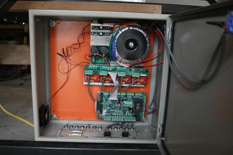
The G203V motor drivers are installed backwards
under the PMDX-134 board. The connectors should
have made this difficult to do, but maybe not that
difficult. You can see the correct orientation by
looking at the images here:
PMDX.COM - Products for CNC and motion control applications
As to the consequences, I am not certain and do
not want to repeat the experiment here. The 70
volts DC ground side would have landed on a pin
that is still intended as a ground for the resistor
that sets the motor current limit. The 70 volts
positive would have landed on the current set
input pin and damage would be likely. We will
work with you to get your drives repaired if
the Vampire's magic was not sufficient to resist
this trial.
The step and direction outputs from the PMDX-126
would have been connected to the motor drive
signals from the G203V, but since the G203V
did not have 70 volts on its power input, there
probably is no damage. If there was, PMDX will
cover it under warranty.
I have now spoken with Chris by phone and know
that his motors are rated for 7 amperes. The photo
shows some kind of heatsink under the G203Vs
but I cannot tell if it is finned or flat, or if it is
also coupling heat to the large panel inside the
box. With motors running 7 amperes, it will be
necessary to have an effective heatsink on the
G203V drivers.
Another good practice would be to route cables
such that the outputs from the G203Vs to the
motor connectors do not run under or along side
of the PMDX-126 or wiring from home and limit
switches. The same would apply to the output
from a VFD inverter for the spindle.
Hang in there Chris. We will try to make this as
painless as possible.
Steve Stallings
PMDX.COM - Products for CNC and motion control applications
 )
)

 .
.
