Reply with Quote
I could not clamp a tool in the spindle. I though the drawbar was stuck in the clamped position. It turned out that it was actually open and couldn't clamp on the tool. There was no tension.
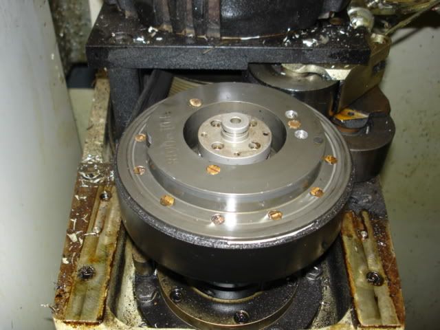
What I found along the way.
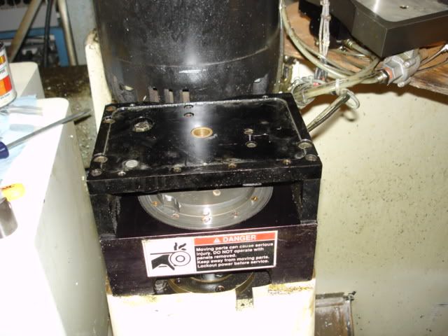
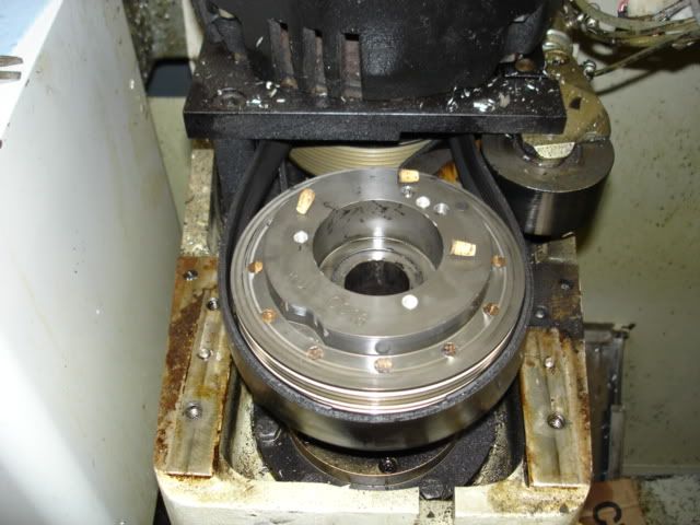
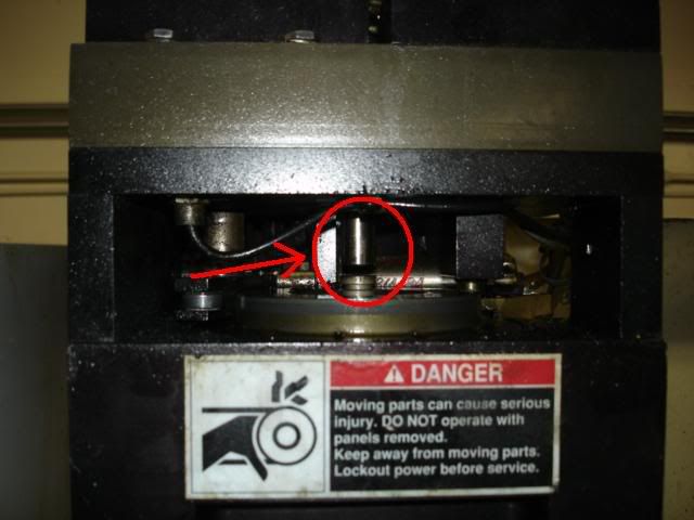
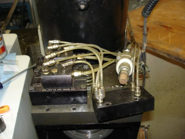
"Waiting on air valve"
The piston would just cycle over and over.
<embed width="600" height="361" type="application/x-shockwave-flash" allowFullscreen="true" allowNetworking="all" wmode="transparent" src="http://static.photobucket.com/player.swf?file=http://vid115.photobucket.com/albums/n299/asherrios/MOV04410.flv">
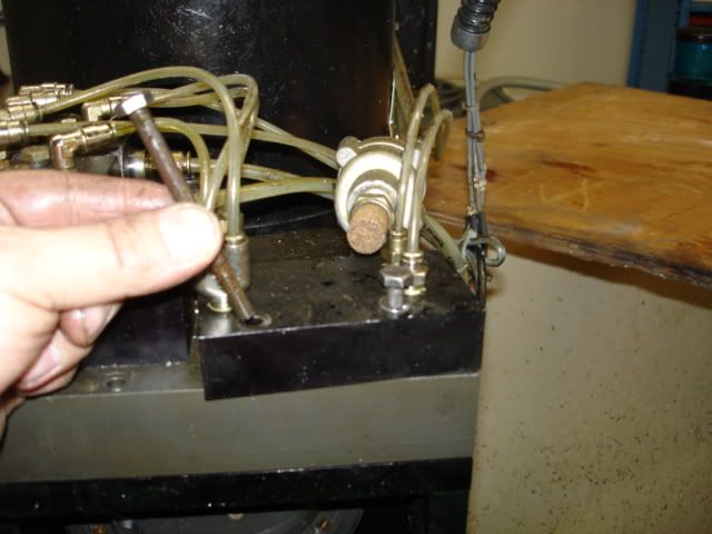
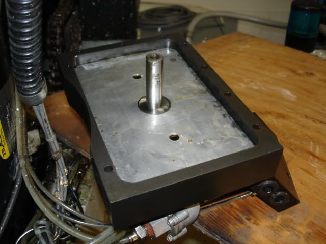
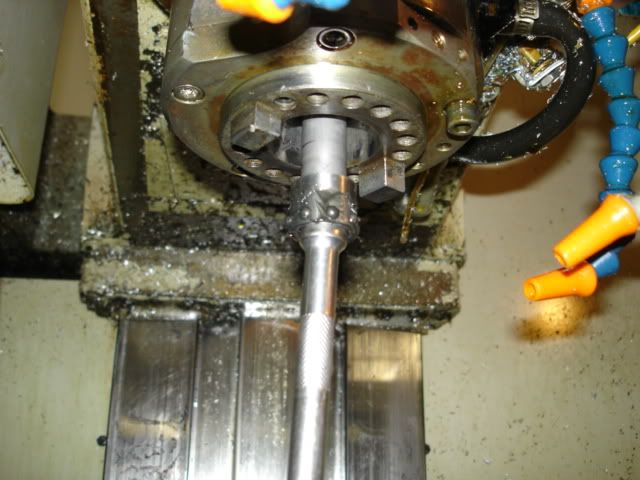
Drawbar up
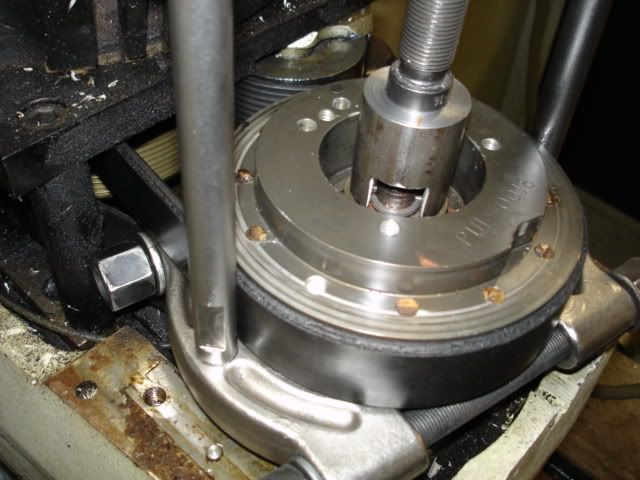
Drawbar down
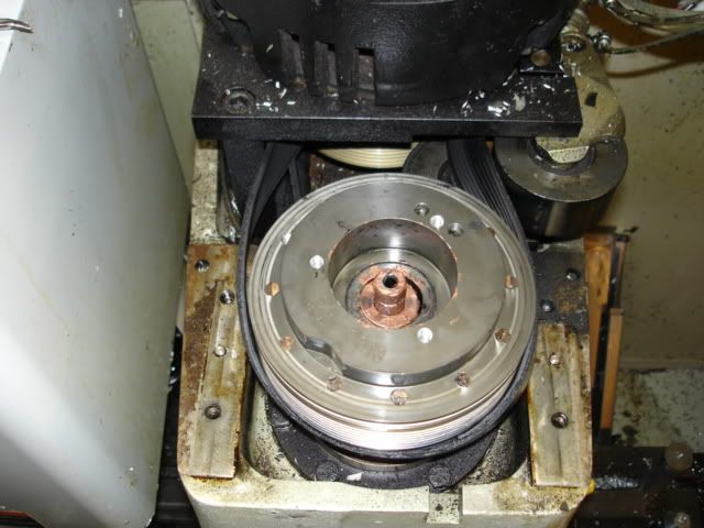
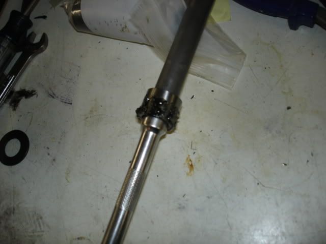
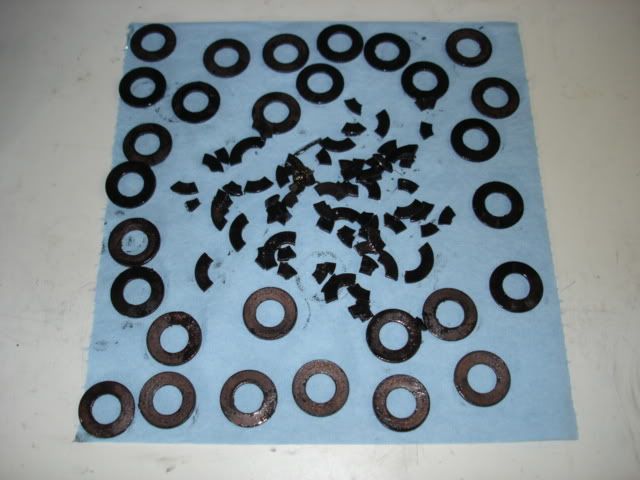
Lots of cracked washers
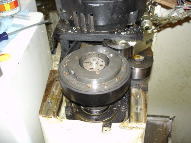
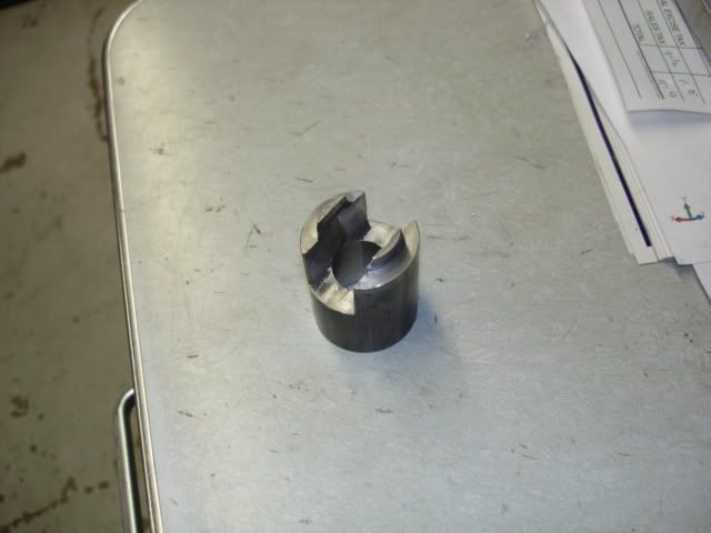
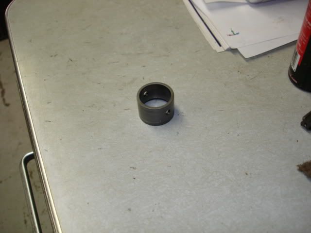
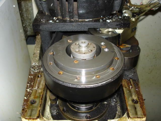
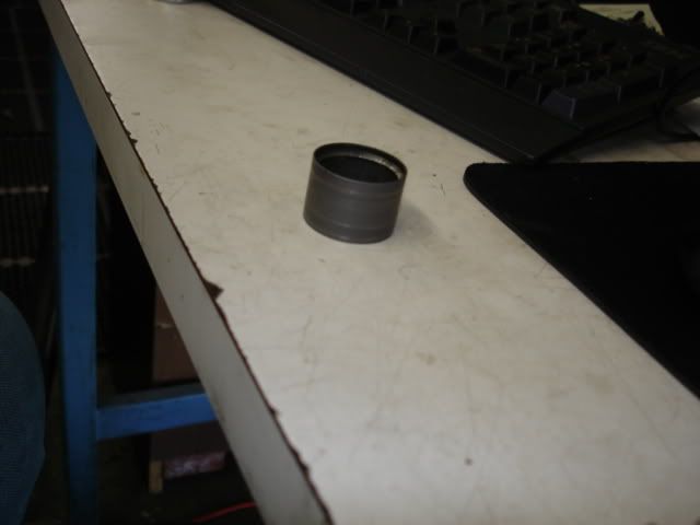
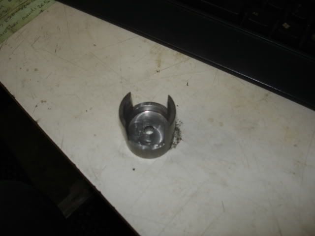
The floater was dinged up on the ID where the bearings ride.

 .
.