Reply with Quote
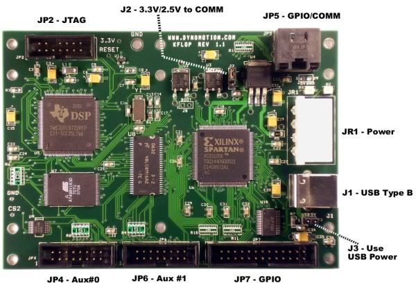
I ordered my KFLOP on 10/26/11 and it arrived in NC on 10/28/11 from CA! I was expecting it to take a week or more, so I wasn't really "ready" when it got here. The KFLOP has two primary I/O connections and two secondary I/O. The two primary connections are JP7, a 20 pin dual row 0.100in ribbon cable connector and JP5 an 8pin modular jack connector (exactly like a network CAT5 connector). In addition there are two other 16 pin dual row 0.100in ribbon cable connectors. For my purposes JP7 more than met my needs.
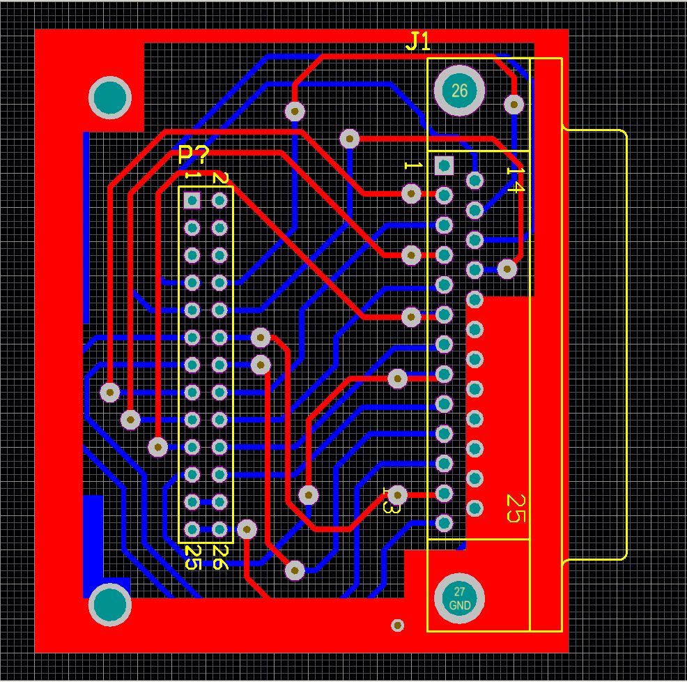
While there are generic "breakout boards" available ( 2x13 0.1" Header (26 position IDC ribbon connector) Breakout Board with Screw Terminals - Winford Engineering ), I wanted to be able to plug my existing DB25 directly into the KFLOP exactly the way it was setup for MACH3 & my desktop. Since one of the main purposes for my A4 is PCBs, I, of course, opted to build a custom interface board.
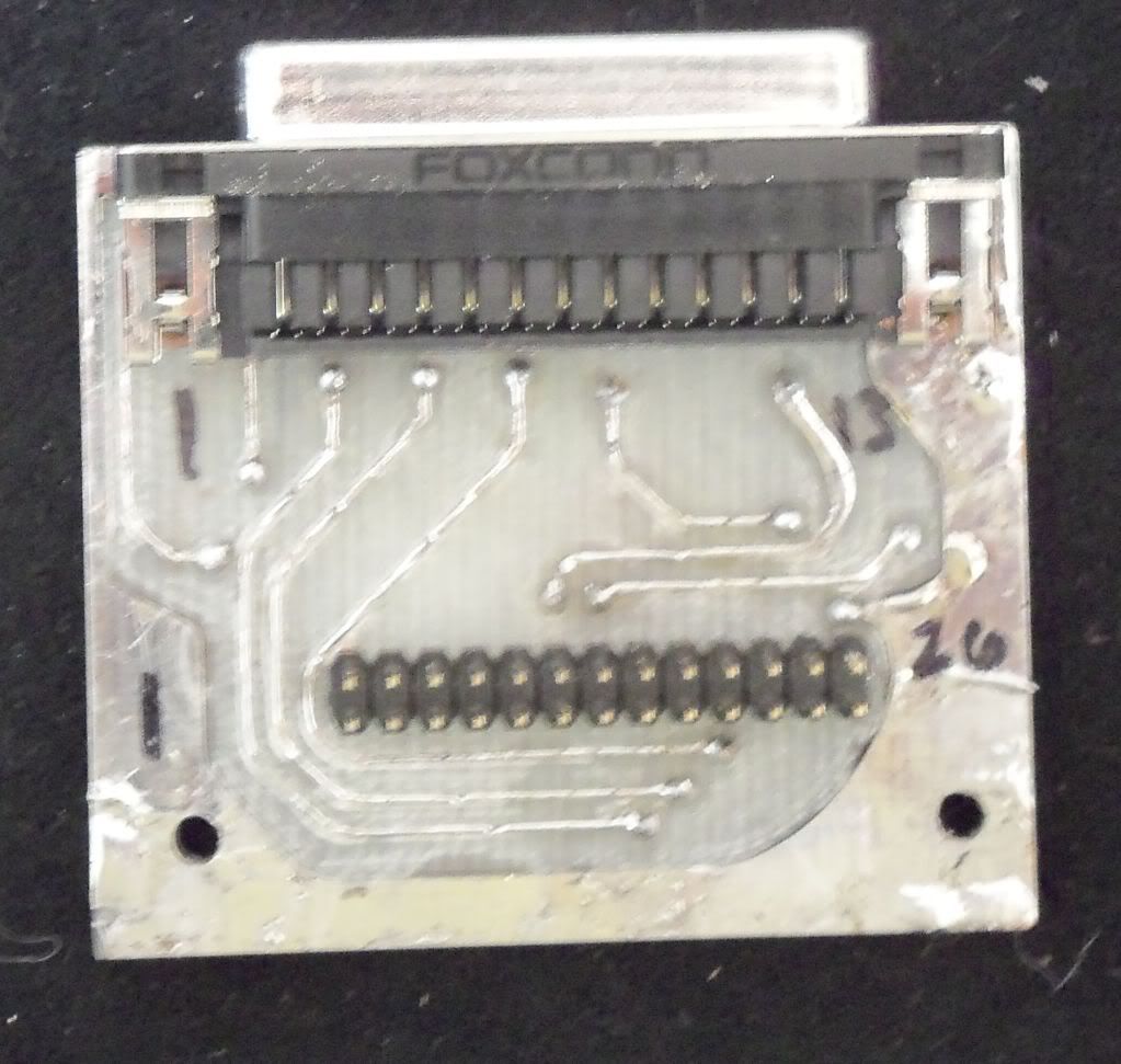
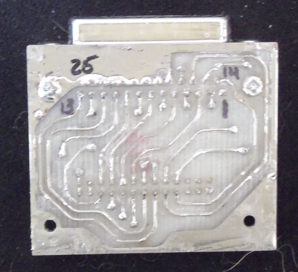
There are only two parts 1) Female DB25 connector 2) 10x2 0.100 Header pins. It is a double sided board, but to make it easy (avoid complicated registration fixtures) I did the gcode as two single sided PCBs from the same sheet of 0.031 FR4 PCB material (obviously the "bottom side" was "mirrored".) When the traces were cut, holes drilled and board cut out I began by inserting all the "VIAs". I used a 0.25mm drill for the VIA holes and "tag ends" from 1/8 watt resistors for the VIAs themselves. The wires were a snug fit and indexed the two PCBs firmly together prior to soldering. Once the VIAs were soldered and clipped I inserted the DB25 and Dual Row pins and soldered them. I did not have any tinning solution on hand, so I simply "tinned" the PCB with solder.
**My camera flash drive just went South, so no more pictures till I get another one, LOL**
I will likely build a more robust interface PCB once I have figured out what all I want to have on it (Spindle control? limit/home switches? etc etc) but for now building this one was all my A.D.D. could stand; I wanted to see if the KFLOP worked! IT DID ;-)
Having said nothing so far but kind things about the KFLOP, it is time for a little dose of reality. The documentation, setup procedure and nomenclature are needlessly convoluted and unintuitive. Tom Kerekes (the only person I have been in contact with for both sales questions and support) has been very quick with help, but even he states:
Rather than wish it were different, I will attempt to cut through some of the engineering double speak and mumbo jumbo so anyone wanting to set up a KFLOP for steppers with a G540 (or Gecko 25xs) can do so without pulling out their hair. The two main applications are KMotion and KMotionCNC. KMotion is mostly a set up and tuning program while KMotionCNC is the primary machine interface for running gcode. KMotionCNC is very straight forward to use and has a clean and intuitive user interface. KMotion assumes you are familiar with the KFLOP and its Nomenclature. To KMotion's credit, every "screen" has a "Help Button" that takes you straight to a detailed explanation of the various functions of the screen. The problem is that the board is so feature rich that finding the "right answer" can be difficult.Yes we realize our controller has a steep learing curve. We are focusing on flexibility, performance, and reliability first. We feel we can focus on ease of use, plug and play, and "canned" configurations later. But it never seems to happen. Everybody has a custom configuration needing special features but at the same time feels that their system should be the default plug and play system :}
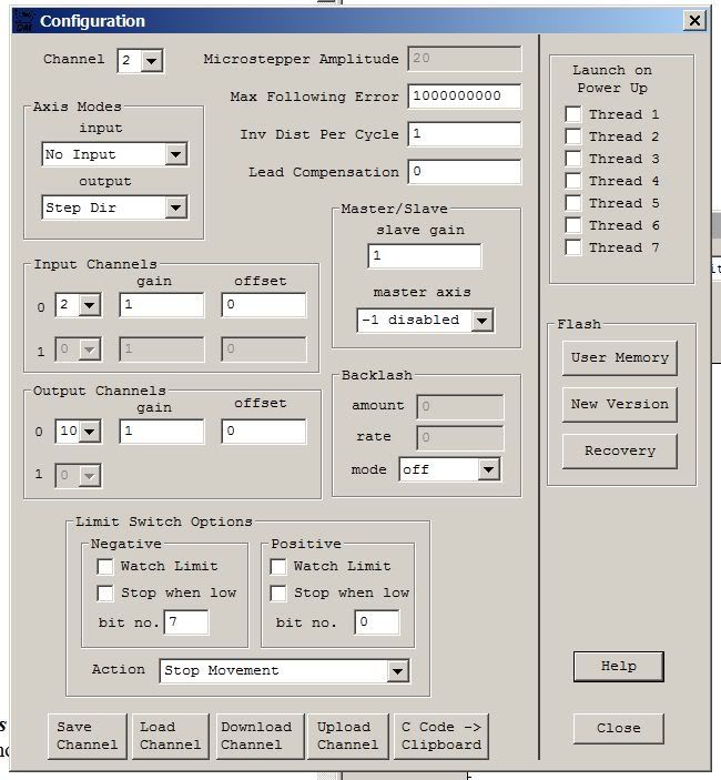
Here is a screen shot of the main configuration screen:
Starting with the upper left-hand corner, there is a "Drop Down" labled "Channel". This is really important! All of the information on the screen pertains ONLY to the selected Channel! For setup of Axis 0, 1, 2 for a typical 3 Axis Stepper machine with X, Y, Z, you will need to "set up" each channel using this screen.
The "Axis Modes" box has two drop downs. For a simple stepper with NO ENCODER the settings are "No Input" and "Step Dir".
The "Master/Slave" defaults to slave gain = 1 master axis = -1 disabled. Best I can tell leave this alone.
The "Input Channels" box defaults to 2, 1, 0. I have no idea what this does, but leave it alone.
The "Output Channels" box is VERY IMPORTANT! Before i explain what to do here, I am going to quote some mumbo jumbo from the help wrt to this box, then I will attempt to make it "clear".
Ok, if you are like me and you read through all of that and then thought to yourself, "Huh?", then here is what you need to know:
The 8 Axes of Step/Dir outputs are normally hard wired to IO bits 8 through 15 on JP7 and IO bits 36 through 43 on JP5. However the first 4 Step/Dir outputs can be multiplexed to connectors JP4 and JP6 if desired. This may be required if JP7 is used for some other purpose such as interfacing to the Kanalog I/O Expander. A global multiplexing bit is used to switch the outputs to the alternate connectors.
Note that the first 8 of 10 I/O pins of Aux #0 and Aux #1 have internal 150 Ohm pull down resistors. Therefore Pins JP4-13, JP4-14, JP6-13 and JP6-14 may not be used in Open Collector mode.
If an axis channel is selected as a Step and Direction axis, the corresponding 2 output pins will be automatically configured as outputs and they may not be used as general purpose IO.
.......
Valid output channel settings 0-31 are allowed for KFLOP. Although only 8 Step and Direction generators are available for KFLOP by adding 8 and/or 16 to the channel number the mode of the Step/Dir Generator can be changed.
Adding 8 to the channel number uses the same generator to be used except the output pins are actively driven (high and low) as 3.3V LVTTL signals instead of only driven low as open collector outputs.
Adding 16 to the channel number switches the generator from Step/Dir to Quadrature output mode.
If your amplifier has opto coupler inputs driven off +5V then open-collector mode is likely to work better. The diagram below shows how the open collector mode works driving the LED of an Opto Coupler with the anode connected to +5V.
.......
However if the amplifier has standard logic inputs then LVTTL outputs should work better.
Quadrature outputs are required for some amplifiers. Quadrature outputs output two A B phases instead of Step/Dir signals. An advantage is that only one signal edge transition takes place for each "step" as opposed to a complete pulse.
To make the Gecko drives work, Add 8 to the channel number and select that number in the first box of "Output Channels". That is if you are working on:
Channel 0 Select "8" from the drop down in the "Output Channels" box.
Channel 1 Select "9" from the drop down in the "Output Channels" box.
Channel 2 Select "10" from the drop down in the "Output Channels" box.
You can leave "gain" @ 1 & offset @ 0 for now. (It turns out "gain" means "direction" in this case, LOL, but there are other places to worry about that.)
The "Backlash" box is pretty straight forward, "rate" = "speed" in steps per second and "amount" = the number of backlash steps. "mode" simply turns Backlash on or off. I have not set my backlash yet, so I currently have it disabled.
I have not setup my Limit switches yet, so I will revisit that in a later post.
"The Launch on Power Up" box is for launching configuration scripts (reffered to in the Help alternately as "threads" and "Programs") at power on. I have been led to believe this is a powerful feature, but I haven't figured it out yet, LOL.
The "Flash" box is an area that I have not yet explored.
Finally, the buttons at the bottom of the page.....wow. This is so counter-intuitive they actually have a "Flash Video" explaining them! ( http://www.dynomotion.com/Help/Flash...ers/index.html ) Following is the cliff notes version:
Following is a sample of the "C Code" data copied for the above screen shot:Code:Save Channel ==> Saves the Settings on the screen to a File on your computer. Load Channel ==> Loads settings from a file TO the Configuration Screen (but NOT to the KFLOP!) Download Channel ==> Moves the CURRENT CHANNEL information from the screen TO the KFLOP. Upload Channel ==> Moves the Settings Already in KFLOP TO the Console Screen. C Code -> Clipboard ==> Parses the settings into text that can be C&Ped into a configuration program. Clicking on this button does not "appear" to do anything, but if you go to a text editor and "paste" the contents of the clipboard the configuration text is what will be pasted.
Code:ch2->InputMode=NO_INPUT_MODE; ch2->OutputMode=STEP_DIR_MODE; ch2->Vel=60000; ch2->Accel=200000; ch2->Jerk=4e+006; ch2->P=0; ch2->I=0.01; ch2->D=0; ch2->FFAccel=0; ch2->FFVel=0; ch2->MaxI=200; ch2->MaxErr=1e+006; ch2->MaxOutput=200; ch2->DeadBandGain=1; ch2->DeadBandRange=0; ch2->InputChan0=2; ch2->InputChan1=0; ch2->OutputChan0=10; ch2->OutputChan1=0; ch2->MasterAxis=-1; ch2->LimitSwitchOptions=0x70020; ch2->InputGain0=1; ch2->InputGain1=1; ch2->InputOffset0=0; ch2->InputOffset1=0; ch2->OutputGain=1; ch2->OutputOffset=0; ch2->SlaveGain=1; ch2->BacklashMode=BACKLASH_OFF; ch2->BacklashAmount=0; ch2->BacklashRate=0; ch2->invDistPerCycle=1; ch2->Lead=0; ch2->MaxFollowingError=1000000000; ch2->StepperAmplitude=20; ch2->iir[0].B0=1; ch2->iir[0].B1=0; ch2->iir[0].B2=0; ch2->iir[0].A1=0; ch2->iir[0].A2=0; ch2->iir[1].B0=1; ch2->iir[1].B1=0; ch2->iir[1].B2=0; ch2->iir[1].A1=0; ch2->iir[1].A2=0; ch2->iir[2].B0=0.000769; ch2->iir[2].B1=0.001538; ch2->iir[2].B2=0.000769; ch2->iir[2].A1=1.92081; ch2->iir[2].A2=-0.923885;
So, to recap, Save & Load affect ONLY the configuration screen, NOT the KFLOP.
Upload & Download move settings between the KFLOP and the Screen, and "Up" means From KFLOP to the PC while "Down" means From the PC to the KFLOP.
To be VERY Clear: You can play with the configuration screen all you like, nothing will be changed on the KFLOP until you click the "Download" button. This MUST BE DONE for EACH CHANNEL!
For Clarity: THIS MUST BE DONE FOR EACH CHANNEL (Axis)
I should probably restate that you MUST "Download" each channel one at a time, but I think everyone is on board with the idea by now.
And, No, you aren't "done yet". It turns out all of this is just to "get you started". I have spent the entire morning working on this, and reading through it I didn't get nearly as far as I had hoped, but I am going to stop here for now and go play some more with my cool new KFLOP :-)
Next up is the "Step Response" screen and some interesting facets of the interactions of the various "screens" in KMotion.
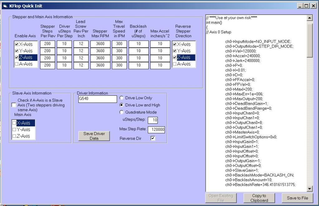
As a footnote, I plan to write a simple front end for creating a stepper configuration file that will allow you to skip configuration in KMotion altogether. It turns out you really don't have to use KMotion to configure the KFLOP at all, and despite Tom's assertion that "Everybody has a custom configuration needing special features", I think many here in the DIY world have pretty common/simple needs. Once you have a configuration file for your machine, all you will need is KMotionCNC or Mach3. The configuration information can be stored on your PC and "Downloaded" to the KFLOP at start up or stored on the KFLOP itself....but that is putting the cart before the horse :-)
Fish